begrenzen, daß die Spannung nach der Diode am Akku nicht über 3.1V geht. [pre] BAS416 5V -----+--2k2--+--|>|--+-------+ | | | | ref +-----+ out| | | +--| MCP |----+ 18M9 | | | 65R | | | + +--| 46 |-----
Referenzspannungstoleranz + 1% Widerstandswertabweichung), da aber der typische Bias-Stron sogar bei 85 GradC 100 mal kleiner ist sollte das trotzdem passen. Zur Anpassung an die temperaturabhängikeit der Ladespannung könnte man einen Teil des 18M9 durch einen hochohmigen NTC ersetzen, da aber im Datenblatt
nur ein geringer Prozentsatz auf der > Intensivstation landet Und der geringe Prozentsatz von 85 Millionen sind nur 10%, also nur 8.5 Mio Betten. Nicht Intensiv, sondern stationär. Die paar Intensiv-Hanseln davon können wir an deinen Baukompressor anstecken, oder? Danke für deine Mithilfe!
Nick M. schrieb im Beitrag #6228165: > Und der geringe Prozentsatz von 85 Millionen sind nur 10% Bullshit. Ständiges Wiederholen der Lüge macht sie nicht auf magische Weise wahr.
Copyright (C) 2003 Motorola Inc *** Attempting to start S81hantro Loading Hantro decoder module: hmp4d: base_port=0x10026800 irq=50 hmp4d: module inserted Loading Hantro encoder module: hmp4e: base_port=0x10026c00 irq=49 hmp4e: Compatble HW found with ID: 0x004c1882 hmp4e: module inserted. Major = 248
sftp auf das VP6500 zu bringen: SFTP-Server 0. Von http://familiar.handhelds.org/releases/v0.7.2/base/armv4l/ folgendes herunterladen und sftp-server daraus entpacken: http://familiar.handhelds.org/releases/v0.7.2/base/armv4l/sshd_3.7.1p1-1_armv4l.ipk 1. ssh root@wlantelefon 2. # mkdir /usr/
Collector-Emitter Voltage BE= 0) 1500 V VCEO Collector-Emitter VoltageB(I = 0) 700 V VEBO Emitter-Base Voltage CI = 0) 10 V IC Collector Current 8 A CM Collector Peak Current pt < 5 ms) 15 A TO - 3 TO - 218 ISOWATT218 o P tot Total Dissipation atcT = 25 C 150 125 50 W T stg Storage Temperature -65 to
Schritt-für-Schritt: http://servokit.com/blog/2016/03/19/adding-mounting-holes-to-the-tvm802a-base-plate/ Gruß, Axel
sicher aufgenommen wird. Kann man hier im Video sehen (ab 3:12): https://www.youtube.com/watch?v=gqUc85uAubs Und ja, man muß bereit sein, da ordentlich Zeit rein zu tun. Kein Plug and Play... Gruß, Axel
Radiobandes mit seinen nur maximal 4Khz FM Hub (UKW Radio max. 75KHZ!) als auch für das Flugfunkband mit 85% Modulationsgrad in AM geht das sogar mit guten Resultaten. Sogar eine Rauschsperre lässt sich nachrüsten. Beides habe ich am Anfang meiner HF Karriere (Liebe Strafverfolgungsbehörden: also vor sehr
CB, WP ?, PB ? und eben AIR empfangen kann. Kam vor Jahren 35 DM. http://cgi.ebay.de/Intersound-MB-85-Multiband-Radio-tragbar-AIR-FM-WB-TV1-/320708367953?pt=Radios_Recorder&hash=item4aabb55651 Es ist aber wirklich miese Qualität!
CHARACTERISTICS AND AC TIMING" für DDR200, DDR266 und DDR333 ein maximales tclk von 12 ns. Also was um 85MHz. Ausserdem habe ich auf genau dem Board einen selbstgeschriebenen DDR Controller mit 100MHz laufen. Der ist leider voll synchron, d.h. das restliche FPGA Design läuft mit 50MHz und sieht ein
dieser fehler nur mit der aktuellen EDK-version auf (9.x), bei 8.x läuft ein standard-design aus dem base system builder einwandfrei. ein unverändertes projekt von 8.x in 9.x übersetzt funktioniert auch. ich denke es liegt an irgendeiner neuen ip-version. habe leider keine zeit und lust es genauer zu testen
Temp. Range Voltage Capacitance Tolerance (Operating or Cap. Change (Ref.Temp.) Temp. Range) -55 to 85 °C -15 to 15 % DC 35 V 10 uF ±20 % -55 to 85 °C (25 °C) 5.Package mark (8) Packaging Packaging Unit L f180mm Reel 3000 pcs./Reel EMBOSSED W8P4 f330mm Reel K 10000 pcs./Reel EMBOSSED W8P4 Product specifications
while executing 'RENAME TABLE `attachement_types` TO `attachment_types`;': SQLSTATE[42S01]: Base table or view already exists: 1050 Table 'attachment_ types' already exists In PDOConnection.php line 90: SQLSTATE[42S01]: Base table or view already exists: 1050 Table 'attachment_ types' already exists In PDOConnection.php line 88: SQLSTATE[42S01]: Base table or view already exists: 1050 Table 'attachment_ types' already exists [/code] mache ich hier was falsch? Die neue Version funktioniert sonst soweit, die alte Version läuft auch einwandfrei
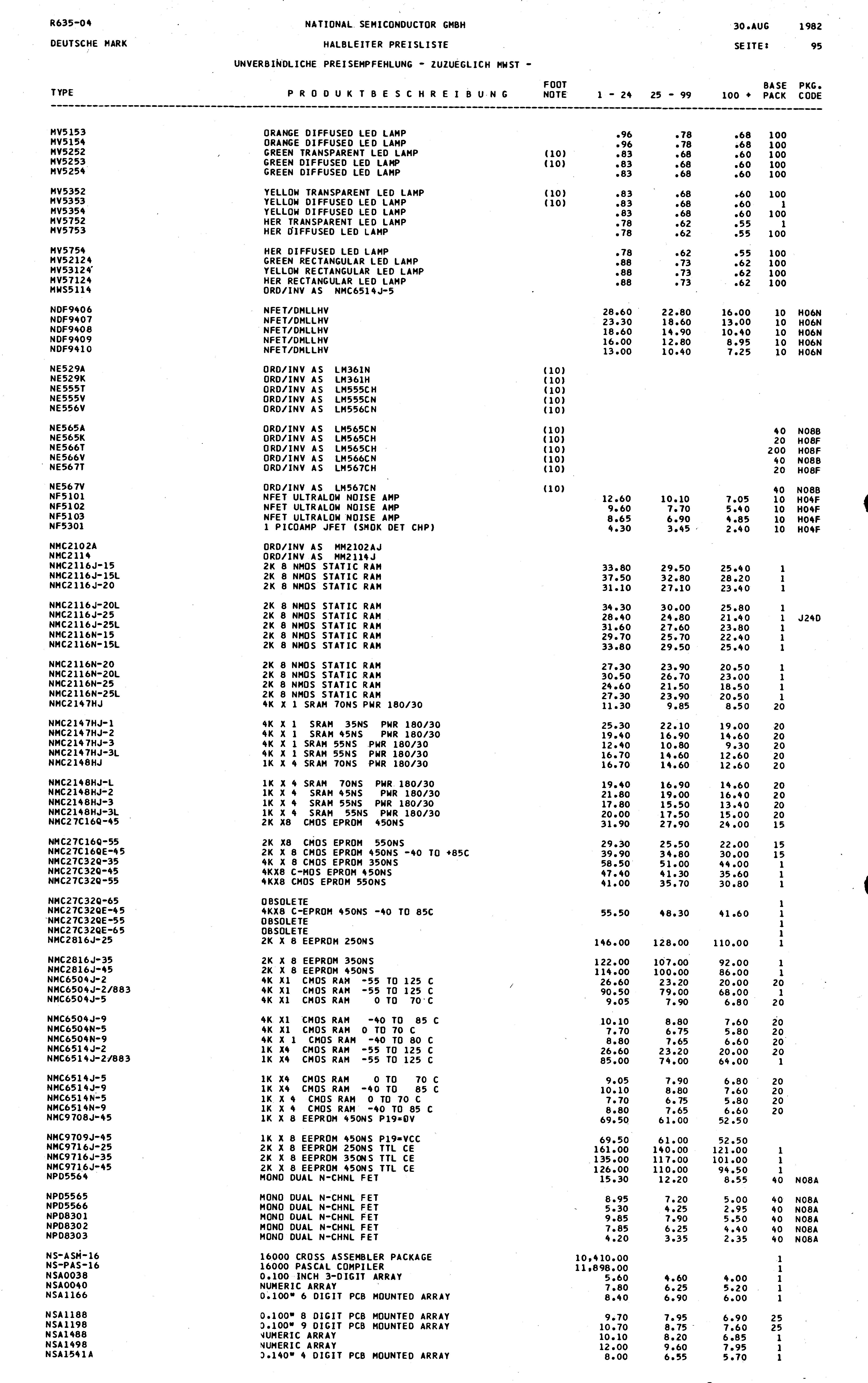
DEUTSCHE SEMICONDUCTOR GMBH SEITE| 95
TYPE FOOT NOTE BASE PKG
NV5153 ORANGE DIFFUSED LED LAMP .96 .78 100
NV5154 ORANGE DIFFUSED LED LAMP .96 .78 100
NV5255 GREEN DIFFUSED LED LAMP .83 .68 100
NV5256 GREEN DIFFUSED LED LAMP .83 .68 100
NV5754 YELLOW TRANSPARENT
Support) zu ASrock greifen, ein Z87-Chipsatz ist vermutlich nicht nötig, der hat genauso wie die einen B85 4GB/s Bus und 16 lanes. Unterschiede gibt es nur in der Perepherie und in der Aufteilung der PCI-Lanes. Wenn du auf overclocking, Raid und übertrieben viel USB3.0-Ports verzichten kannst, ist ein
beQuiet oder konsorten. allerdings würde ich für eine perfekte zusammenstellung mal in ComputerBase Forum rüberschauen EDIT: gerade gesehen Budget=750€ http://geizhals.de/zotac-geforce-gtx-760-zt-70401-10p-a967266.html http://geizhals.de/intel-core-i5-4440-bx80646i54440-a986966.html http
Betrieb. Im A Betrieb ist der Ruhestrom 2A. Als Leistung ist angegeben A Betrieb 2x18W und B Betrieb 2x85W. Ich hatte mir damals auch eine gebraucht gekauft und auch diese hatte mal eine Reparatur nötig. Einen Unterschied von A und B ist zu hören, aber halt nur im Vergleich und bei bestimmter Musik. Aber
Im A Betrieb ist der Ruhestrom 2A. Als Leistung ist angegeben A Betrieb > 2x18W und B Betrieb 2x85W. Das ist im groben auch die Groessenordnung wo sich mein A700 bewegt. Ich denke mal mehr ist in einem Wohnzimmer auch nicht akzeptabel. Die haben einfach zuviel Verlustleistung. Ich hatte z.b mal
Frequency,5 C to 85 C 0.1 - 10 MHz f 4.75V < V < 6.0V OSC DD Oscillator Transconductance, g V -4.75V, T = 85 C 2000 - - µS M DD A Multiplex Frequency, f f = 10MHz - 500 - Hz MUX OSC Time Between Measurements f = 10MHz -
aktzeptabel? Effizienz ist schon ein Thema, hab ein knappes Leistungsbudget. 40mA @ 16V. Das sind bei 85% Effizienz 165mA @ 3,3V. Ich lese gerade im Design Guid: > Use a 3.3V Regulator with at least 300mA output current. Für die Leistungsspitzen kann ich ein paar Elkos auf der 16V Ebene vorhalten
Netzwerkschnitstellen bekommen bei Kabellängen >15m schon Probleme. Z.b. sind nach Norm eigentlich bis zu 100m bei 100BASE-TX drinnen. Das schaffen aber oftmals nur Industriebaugruppen. Es gibt auch diverse Phy Hersteller, die das nicht wirklich interessiert. Da findet man PHYs bei denen die Hersteller noch nicht mal ausprobiert
0.001 10 µA DETECTOR Collector-Emitter Breakdown Voltage (C = 1.0 mA,FI = 0) BVCEO 30 100 V Collector-Base Breakdown Voltage (C = 100 µA,FI = 0) BVCBO 70 120 V Emitter-Collector Breakdown Voltage (I = 100 µA, I = 0) BV 7 10 V E F ECO Collector-Emitter Dark Current (VCE= 10 V,FI = 0) CEO 1 50 nA Collector-Base
Colpitts VCO There are 3 types of BJT Colpitts VCOs. Common-Collector, Common-Emitter and Common-Base. The most used is Common-Collector configuration where the output is often taken from the collector terminal, simply acting as a buffer for the oscillator connection at the base-emitter terminals. This
30 mA Peak Forward Current [1] 100 mA Reverse Voltage 5 V Operating/Storage Temperature -40°C To +85°C Lead Solder Temperature [2] 260°C For 3 Seconds Lead Solder Temperature [3] 260°C For 5 Seconds Notes: 2. 2mm below package base.Pulse Width. 3. 5mm below package base. SPEC NO: DSAL9399 REV NO: V.3B
DETECTOR Breakdown Voltage Collector to Emitter IC= 1.0 mA,FI = 0 BV CEO All 70 100 V Collector to Base IC= 10 µA,FI = 0 BV CBO All 70 120 V Emitter to Collector IE= 100 µA,FI = 0 BV ECO All 7 10 V Leakage Current Collector to Emitter VCE = 10 V,FI = 0 ICEO All 1 50 nA Collector to Base VCB = 10 V,FI = 0 ICBO All 20 nA Capacitance Collector to Emitter VCE = 0, f = 1 MHz C CE All 8 pF Collector to Base VCB = 0, f = 1 MHz C CB All 20 pF Emitter to Base VEB = 0, f = 1 MHz C EB All 10 pF 2 www.fairchildsemi.com CNY17-1, CNY17-3, CNY17-2, CNY17-4 Rev. 1.0.2 C N Y Isolation Characteristics 1 7 Characteristic
boolean r w 2 Push-Pull SPIKEF 0x1 1 1, boolean r w 3 spike filter enabled ANG_BASE 0xFFF 4095 12,uint16_t r w 4:15 Angle Base sets the 0° angle position: 7FFH +179.912° Register: OFFX Offset: 0xA Binary: 1111111111111111b =================================
1 1, boolean r w 2 Open Drain FIRUDR 0x1 1 1, boolean r w 2 FIR_MD = ‘10’ (85.3 μs) ORTHO 0xF001 61441 3,uint16_t r w 4:15 12-bit signed integer value of orthogonality correction Register: MOD4 Offset: 0xE Binary: 1111111111111111b ===============
Uboot für den Grasshopper gepatched. http://www.mikrocontroller.net/topic/151776#new Für das OEM-base oder plus -Board musst du Uboot aber zusätzlich an die geänderten Speicherbereiche anpassen.
Sack voller Dateien, aber keine die mit setup anfängt. Allerdings eine icnova.c oder eine icnova_base.c. Da mein buildroot den grasshopper nicht kennt, kann ich jetzt auch schlecht sagen, was welche der Dateien der setup.c entsprechen könnte...
stant during the black level reference portion of the video upon the differential DC voltage at the bases of Q3 and Q4. waveform. The clamp comparator, when gated on during The Q3 and Q4 differential base voltage is determined by this reference period, will charge or discharge the clamp the contrast control
Width) - Derating Linear From 25BC Per Segment 0.4 mA/BC Topr Operating Temperature Range -35BC to 85BC Tstg Storage Temperature Range -35BC to 85BC ELECTRO-OPTICAL CHARACTERISTICS : ( Ta = 25 BC ) TEST SYMBOL PARAMETER CONDITION MIN. TYP. MAX. UNIT VF Forward Voltage , Per Segment(DP)IF= 40mA 9.0(1.8
28-Lead Plastic SSOP –40°C to 85°C LEAD BASED FINISH TAPE AND REEL PART MARKING PACKAGE DESCRIPTION TEMPERATURE RANGE LTC3703EGN LTC3703EGN#TR 3703 16-Lead Narrow Plastic SSOP –40°C to 85°C LTC3703IGN LTC3703IGN#TR 3703I 16-Lead Narrow
80A n Mono- or bistable coil n 5kV/10mm coil-contact n Reinforced insulation n Ambient temperature 85°C Typical applications Domestic appliances, heating control, lighting control F0177-C Z b Approvals Coil Data, DC coil VDE REG.-Nr. 6106, UL E214025, cCSAus 14385 Coil voltage range 5 to 110VDC Technical
200 250 A Over Temperature, –40°C to +85°C 240 300 A TEMPERATURE RANGE Specification –40 +85 °C Operating –55 +125 °C Storage –55 +125 °C Thermal Resistance θJA 150 °C/W Specifications the same as XTR115U and XTR116U. NOTES: (1) Does not include
diode, ifb breakdown voltage is above 10V so this method is more un- current is injected into the base of Q2, this transistor turns common. In either case, once the SCR is turned on a large on, and a collector current beta times its base current flowsm current will flow froCCVto ground, causing the CMOS cir- into the base of Q1. Q1 in turn amplifies this current by beta cuit to malfunction and possibly damage itself. and feeds it back into the base of Q2, where the current is I CMOS SCR problems can be minimized by proper
■ Noise Figures less than 2dB (Rs 200 ohm) GROUND 1 8 INPUT 50 OHMS APPLICATIONS 2 7 INPUT COMMON BASE ■ Bandwidth 300MHz OUTPUT CURRENT SET SL OUTPUT 3 560 6 INPUT COMMON EMITTER ■ Supply Voltage 2-15V (Depending on Configuration) GAIN SET Vcc 4 5 ■ Low Power Consumption Top view DP8 APPLICATIONS ■
10 Mw D Collector-emitter Breakdown V (BR CEO 30 V Voltage Operating temperature range Topr -35 to 85 °C Storage temperature range Tstg -35 to 85 °C ◆ ELECTRICAL AND OPTICAL CHARACTERISTICS (Ta= 25°C) Parameter Symbol Test Conditions Min Type Max Unit Collector-emitter BVCEO C =100μA ,IB=0 30 100 V Breakdown
30 30 30 Temperature: Operating °C –30 to +70 –30 to +70 –30 to +70 –30 to +70 Storage °C –30 to +85 –30 to +85 –30 to +85 –30 to +85 Agency Approvals UL, CE, CSA, UL, CE, CSA, UL, CE, CSA, UL, CE, CSA, RoHS; UKCA UKCA UKCA UKCA * Compatible with Raspberry Pi G4IDC5-SWandG4IDC5-SWNCmodules See page
ihm passierte. Ob er auch künftig wieder Base-jumpen wolle, wurde er danach gefragt. Klar wolle er, war seine Antwort. Wenn der beim nächsten mal zerfetzt am Boden ankommt. Soll dann die Medien-Mitleidsmaschine auch für ihn trommeln? Oder sind
100,1%. Später rechnete ihr der damalige Finanzminister Gunnar Sträng vor, dass sie als Rentnerin »nur« 85% Steuern zahlen musste."
an indication for the hub’s full or half duplex capabilities. Descriptions are as follows: 10 H 10BASE-T aue16f.eps 10 HF 10BASE-T full duplex 100 H 100BASE-TX The word SIGNAL blinks once every two seconds right below the word Hub. Go to the wiring closet to view a 100 HF 100BASE-T full duplex light that blinks once every two seconds at the port to which the cable is connected. 100 HF4 100BASE-T full duplex, 100BASE-T4 15 MicroScanner Pro Users Manual M ICROSCANNER PRO also Identifies workstations. 3. When M ICROSCANNER P ROdisplays PC and the cable 1. Connect the cable to be tested to the
segment drivers are turned off, enabling the display to be used for other functions. ICM7216AlJl -25 to 85 28 Ld CERDIP F28.6 ICM7216BlPl -25 to 85 28 Ld PDIP E28.6 ICM7216DlPl -25 to 85 28 Ld PDIP E28.6 CAUTION: These devices are sensitive to electrostatic discharge. Users should follow proper IC HandliFile
shortermal shutdown and current limit protection 1 circuits, or excessive temperatures. n −40˚C to +85˚C ambient temperature range A Highlights Applications D n No external components required (fixed output voltagen Simple high-efficiency step-down (buck) regulator C versions) n On-card switching regulators

 Bild
Bild