-
PDF
CJ125.pdf
IVCC 76 mA Current consumption IVCCS 4 mA Pump current control Offset voltage V off -10 10 mV Input current -40°C • T j< 150°C IUP,UN -1 1 µA Input offset current -40°C • T j< 150°C Ioff -1 1 µA V UN< VUP; PA
in „Bosch CJ125 Lamda Sonden IC“ · Mikrocontroller und Digitale Elektronik ·
-
PDF
CJ125_Product_Info.pdf
IVCC 76 mA Current consumption IVCCS 4 mA Pump current control Offset voltage V off -10 10 mV Input current -40°C • T j< 150°C IUP,UN -1 1 µA Input offset current -40°C • T j< 150°C Ioff -1 1 µA V UN< VUP; PA
in „Heizelement an UC mit Diagnose. Verständis Frage“ · Mikrocontroller und Digitale Elektronik ·
-
PDF
WS2813_LED.pdf
Refresh Frequency updates to 2KHz, Low Frame Frequency and no Flicker appear in HD Video Camera. 250us or more of reset time, it won’t cause wrong reset while interruption, it supports the lower frequency and inexpensive MCU. There’re in a choice of 18mA or 5mA current version, and also in a choice of
in „WS2812 und WS2812b Qualitätsprobleme!“ · Analoge Elektronik und Schaltungstechnik ·
-
Datei
patricia_Lcd.asm
.include "m8def.inc" .def temp1 = r16 .def temp2 = r17 .def temp3 = r18 .def temp4 = r19 text: .db "Uss= ",0 ; Stringkonstante, durch eine 0 abgeschlossen text1: .db " ",0 ;soll im erste Zeile mit adresse 0x05 text2
in „Dezimale Umwandlung vor LCD Ausgabe“ · Mikrocontroller und Digitale Elektronik ·
-
Datei
Signalverfolgung.asc.txt
SYMATTR Type ind SYMBOL ind2 496 128 R0 SYMATTR InstName L4 SYMATTR Value 5.2mH SYMATTR Type ind SYMBOL res 560 -80 R90 WINDOW 0 0 56 VBottom 2 WINDOW 3 32 56 VTop 2 SYMATTR InstName R1 SYMATTR Value 5k SYMBOL Misc\\signal 240 -48 R0 WINDOW 3 -109 -38 Left 2 WINDOW 123 0 0 Left 2 WINDOW 39 0 0 Left 2 SYMATTR InstName V1 SYMATTR Value SINE(0 230V 50Hz) SYMBOL Misc\\signal -352 128 R0 WINDOW 3 -299 -64 Left 2 WINDOW 123 0 0 Left 2 WINDOW 39 0 0 Left 2 SYMATTR InstName V2 SYMATTR Value PULSE(0 1 0 1us 1us 498us 1m 100)
in „Leitungssucher mit hoher Leistung“ · HF, Funk und Felder ·
-
Datei
uhr2.asm
.include "m8def.inc" .org 0x000 .def temp = r16;Temp .def temp1 = r17;Temp1 .def temp2 = r18;Temp2 .def temp3 = r19;Temp3 .def teiler = r20;Teiler für Timer (1 Sekunde) .equ adresse = 0x0060;Startadresse für LCD-Speicher
in „Hex Wert -> Dezimal an LCD ausgeben“ · Mikrocontroller und Digitale Elektronik ·
-
PDF
isp_man2.pdf
blank device. Note that this will also ! erase the User Electronic Signature portion of the EE and all UES information will be lost. This also resets the secure device bit. Blank Check Verifies that the EE array is in a completely blank state. All EE cell locations should verify as a ‘1’. Program ‘Program
in „Philips PZ5032 CPLD freies Development Tool?“ · FPGA, VHDL & Co. ·
-
Datei
MINI68.TXT
A7)+,D3-D5; RTS; L200E8: BSR.B L200F2; TST.L D0; MOVEM.L (A7)+,D3-D5; RTS; L200F2: TST.L D0; BPL.B US_DIVIDE; NEG.L D0; BSR.B US_DIVIDE; NEG.L D0; NEG.L D1; RTS; US_DIVIDE: MOVE.L D1,D3; SUBQ.L 1,D3; BEQ.B L20126; MOVE.L D3,D4; AND.L D1,D4; BNE.B L20120; LSR.L 1,D1; MOVEQ.L -1,D4; L20110: LSR.L 1,D1;
in „[S] MPU (Z80/6502/68k)“ · Markt ·
-
PDF
2303974.pdf
L 0.4 0.4 V IN= 1.8V VIN= 2.5V 0.35 V ON/OFF 1.5V -8V 0.35 VON/OFF 1.5V -8V PW = 300us, D < 2% 0.3 PW = 300us, D < 2% T = 125 C 0.3 J O )0.25 ) 0.25 TJ= 125 C ( ( O 0.2 TJ= 25 C ,O 0.2 D D V0.15 V 0.15 T = 25 C J 0.1
in „Bauteil gesucht Dusch WC“ · Mikrocontroller und Digitale Elektronik ·
-
PDF
Firmware_buglist_2.06.3.pdf
base scaling strange behavior. When you apply e.g. 1kHz signal, set time base to 80us/DIV and move the waveform to 500us/DIV (bug only in 4/40k memory depth, 512k/1M/2M works fine): When you now change time base to 40uS/DIV the falling edge (which should
-
PDF
OZ890-Datenblatt.pdf
B N B N BN B N B N B N B N BN B N B N B N B N BN 1 1 M2 1 M2 1 M2 1 M2 1 M2 1 M2 1 M2 1 M2 1 M2 1 M2 1 M2 1 M2 1 M2 1 N I 1 3 2 3 2 3 2 3 2 3 2 3 2 3 2 3 2 3 2 3 2 3 2 3 2 3 2 N D 2 G W W W W W W W W W W W W W K K / / / / / / / / / / / / / 1 1 5 5 5
in „Schaltung für aktiven 3s Balancer gesucht“ · Analoge Elektronik und Schaltungstechnik ·
-
 Bild
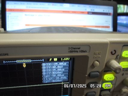
Foto eines Oszilloskops mit Messwerten
2 Channel 100MHz 1GSa/s MENU ON/OFF A->X:-25.00us A->Y:40.0mV B->X:25.00us B->Y:0000mV ΔX:50.00us f:20.0kHz ΔY:0000mV 06/07/2025 05:28 PM
in „[V] Rigol DS1102E (fast Neu), 200,-€ incl. DHL-Versand in DE“ · Markt · · Fotos
-
Datei
pwm.txt
lowest level, then ramp up to maximum dopwm: ldi r17,MINBRIGHT ; R17 holds current brightness level l1: ldi r18,NCYCLES ; R18 counts PWM cycles, and hence pulsation speed l2: cbi LEDPORT,LEDBIT ; Output pin low, LED on mov r16,r17 ; R16 controls length of delay (= R17) rcall delayn4us ; Call delay subroutine
in „PWM RGB-LED umschalten“ · Mikrocontroller und Digitale Elektronik ·
-
 Bild
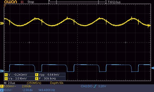
Oszilloskop-Messung zweier Signale
owon Stop T:612,us 1 2 V : -0,243mV 1 Vpp : 6.641mV 1 Va : 3.516mV 1 F : 309.1kHz M: 2.0us (250MS/s) Depth:10k 1 5.00mV~ 2.00div 2 10.0V- -2.98div 149.480KHz CH2:DC- 3.20V
in „Mal ganz allgemein zur Spule vom Schaltregler.“ · Analoge Elektronik und Schaltungstechnik · · Oszi-Bilder
-
Datei
DOGM_INIT_Assembler.asm
LCD-Routiinit ****** ;***************************************************** ;Electronic Assembly DOG-M xxx LCD's ;LCD initialisieren in 13 Schritten ;LCD initialization takes 13 steps ;LCD initialisoinin 13 vaiheet InitLcd movlw D'200' ; 200 ms Pause/Taukko movwf loops call WAIT movlw FUNCTSET8 ; 1.)
in „EA DOGM 162, bei doppelter höhe fehlt eine Zeile...“ · Mikrocontroller und Digitale Elektronik ·
-
PDF
Energizer_ultimate_lithium.pdf
Discharge Drain (mA) (alkaline shown for comparison) Discharge Profile Temperature Effects on Capacity Constant Current Discharge Constant Current Discharge 1 mA 10 mA 100 mA 25 mA 250 mA 1000 mA 1.8 3500 3000 ) 1.6 h
in „Aufwachprobleme ESP8266 (Wemos D1)“ · Mikrocontroller und Digitale Elektronik ·
-
PDF
Control_S03_Sch_4011.pdf
) 38120 10AhB140 40V 1A SMB oder DO? Shottky 2 3 4 LiFePo4-1-8 PC817C CTR200-400% 80/500V 18/18us DIP4 0,23€ 12,8V 5 LiFePo4 3,2V 4s2p 12,8V 2x6Ah=12Ah 8mR 35A 55A 3Achg 32700 145g Nickel She+Ub+Halter LTV417 0.19€ DIL4 50
in „Laufzeitbegrenzung für 12V Pumpe mit Akku, Solarmodul, Step-Up, Zeitschaltuhrbetrieb LED-Anzeige MPP“ · Projekte & Code ·
-
PDF
gedore_rueckruf_drehmomentschluessel.pdf
8-75 375 0,5 N·m 600 1477978 3550-07 3/8“ 8-70 6-52 2,5 N·m 600 1654934 4200-02 9x12 20-150 15-110 461 1 N·m 800 1379534 3550-10 ½“ 10-100 8-75 5 N·m 1000 7600990 4201-01 14x18 20-200 15-150 475 1 N·m 900 1379526 3550
in „Rückruf: Gedore Drehmomentschlüssel.“ · Mechanik, Gehäuse, Werkzeug ·
-
PDF
datasheet.pdf
, Rev. 1.1 62 Freescale Semiconductor Specifications Auto Clear WR1/R Set WR1/RD Write “1” Slot 117us 5us Figure 48. Write 1 Timing Set WR1/RD Auto Clear WR1/RD Set WR1/RD Auto Clear WR1/R Read Timing Read “0
in „PHILIPS VP5500 VoIP Telefon bei Pollin“ · Mikrocontroller und Digitale Elektronik ·
-
Datei
DS1820LCD.asm
detect cpi a1, 46 * xtal / 100000 / 21 ;1 after 15us rcall _w1r3 ;14 dec a1 ;1 brne _w1r2 ;2 sbis w1_in, w1_pin ; check short circuit clc reti ; int enable _w1r3: rcall _w1r4 ;7 delay 14 cycle _w1r4: ret ;4 ;-----
in „1-Wire und DS1820 Testprog“ · Mikrocontroller und Digitale Elektronik ·
-
PDF
201612120034585136.pdf
current I V =0V 1 uA SD EN VINV ENV, Reverse current IREV VOUT=5V, Current 1 uA flow to IN V =V =5V, Main-FET ON resistance (1) RON IN EN 80 mΩ OUT=500mA VEN0V, Auto-discharge FET ON resistance RDCHG 65 Ω VINV OUT=5V
in „Unbekannter SMD-Marking-Code CP5R und 4061 1616“ · Analoge Elektronik und Schaltungstechnik ·
-
PDF
Butler_OT_XO.pdf
low-impedance drive to match to the crystal. It is an emitter follower, which means no voltage gain (V/V = 1) but provides current amplification. The Butler emitter follower is a good performing circuit for a high-frequency overtone operation. 11.2 Butler’s Emitter Follower Oscillator Operation ward. Let us
in „3rd-OT-Oszillator mit NE602 (an Pin 6 und 7)“ · HF, Funk und Felder ·
-
Datei
Sample_LCD-4BIT_Mode.asm
reti ;6 TC1 Capture reti ;7 TC1 Compare Match A reti ;8 TC1 Compare Match B reti ;9 TC1 Overflow reti ;10 TC0 Overflow reti ;11 SPI Transfer Complete Handler reti ;12 UART RX Complete reti ;13 UART Data Empty reti
in „LCD im 4 BIT Modus“ · Mikrocontroller und Digitale Elektronik ·
-
Datei
irmp.c
inverted data bits + stop bit * data: 5 address bits + 10 command bits * * Theory: * * data "0": data "1": * ------________________ ------______________ * 275us 775us 275us 1900us * * Practice: * * data "0": data "1": * ------________________ ------______________ * 310us 745us 310us 1780us * *----------
in „ATmega resettet dauernd“ · Mikrocontroller und Digitale Elektronik ·
-
Datei
irmp.c
inverted data bits + stop bit * data: 5 address bits + 10 command bits * * Theory: * * data "0": data "1": * ------________________ ------______________ * 275us 775us 275us 1900us * * Practice: * * data "0": data "1": * ------________________ ------______________ * 310us 745us 310us 1780us * *----------
in „IRMP - Infrared Multi Protocol Decoder“ · Projekte & Code ·
-
 Bild
Oszilloskop-Screenshot eines digitalen Signals
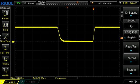
RIGOL T'D H 200us 1.00GSa/s T D -600.000000us T 1 840mV Horizontal Period Freq Rise Time Fall Time +Width -Width Utility IO Setting Sound Language English Pass/Fail Record System Rise<34.0us Fall=82.0us Freq=***** 1 = 2.00 V 2 = 1.00 V
in „Quick&dirty - schnelle Problemlösungen selbst gebaut“ · Projekte & Code · · Oszi-Bilder
-
Datei
sketch_speed_cadence_final.ino
endif // Parameter to controll the Pedelec #define TIMEOUT_CADENCE 1000 // after 1s no signal we are inactive #define TIMEOUT_MS 3000 // 8s = 2.2m * 60*60s/1000m) = 7.92 s #define DIAMETER 2.224 // distance a wheel makes with 1 turn #define SPEED_MIN 6 // 6km/h below no cadence required
in „E-Bike legalisieren (PAS+Speed->Gas)“ · Fahrzeugelektronik ·
-
Datei
radio.c
this does nothing. */ static void set_rx_mode(void) { uint8_t config; get_register(CONFIG, &config, 1); if ((config & _BV(PRIM_RX)) == 0) { config |= _BV(PRIM_RX); set_register(CONFIG, &config, 1); // the radio takes 130 us to power up the receiver. _delay_us(65); _delay_us(65); } } /** * Switch the
in „NRF24L01 scheint nicht zu senden (MAX_RT)“ · Mikrocontroller und Digitale Elektronik ·
-
Datei
pwm.txt
lowest level, then ramp up to maximum dopwm: ldi r17,MINBRIGHT ; R17 holds current brightness level l1: ldi r18,NCYCLES ; R18 counts PWM cycles, and hence pulsation speed l2: cbi LEDPORT,LEDBIT ; Output pin low, LED on mov r16,r17 ; R16 controls length of delay (= R17) rcall delayn4us ; Call delay subroutine
in „PWM RGB-LED umschalten“ · Mikrocontroller und Digitale Elektronik ·
-
PDF
QH7938_ETC.pdf
下降 7.5 V VCC_OVP VCC过压保护阈值 19 V VCC_CLAMP VCC钳位电压 23 V VCC 上升, ICC_UVLO VCC关断电流 33 50 uA VCC V CC_ON1V FOP10kHz, I CC VCC作电流 Load=100pF 1 2 mA FB 反馈 VFB_FALL FB 下降阈值电压 FB 下降 0.1 V VFB_HYS FB 迟滞电压 FB 上升 0.08 V VFB_OVP FB 过压保护阈值 1.6 V TON_MAX 最大导通时间 25 us TOFF_MIN 最小关断时间 4.5 us TOFF_MAX 最大关断时间 100 us 电流采样
in „Sperrwandler - Dimensionierung Ausgangselko“ · Analoge Elektronik und Schaltungstechnik ·
-
PDF
E0124N10.pdf
CONTROLLER Figure 3-32. Timings of Access Cycles Other than Memory Name: Value:960.0ns 975.0ns 990.0ns 1.005us 1.02us 1.035us 1.05us 1.065us 1.08us 1.095us 1.11us 1.12 Access cycle other than memory C/BE0- 0 C/BE1- 0 C/BE2- 0 C/BE3- 0 Read 0 Write 0 Refresh 0 Mode 0 Memory 0 ADD 0 FMS0 0 FMS1 1 FMS2 1 FMS3
in „VGA Grafikkarte mit AVR und 8MB SDRAM“ · Projekte & Code ·
-
PDF
MX25L12805D__3V__128Mb__v1.2.pdf
Supply Operation - 2.7 to 3.6 volt for read, erase, and program operations • Latch-up protected to 100mA from -1V to Vcc +1V PERFORMANCE • High Performance - Fast access time: 50MHz serial clock - Fast program time: 1.4ms/page (typical, 256-byte per page) and 9us/byte (typical) - Fast erase time: 60ms/
in „FLASH Memory Chip im Lenovo X200 von 8 MB auf 16 MB vergroessern“ · PC Hard- und Software ·
-
 Bild
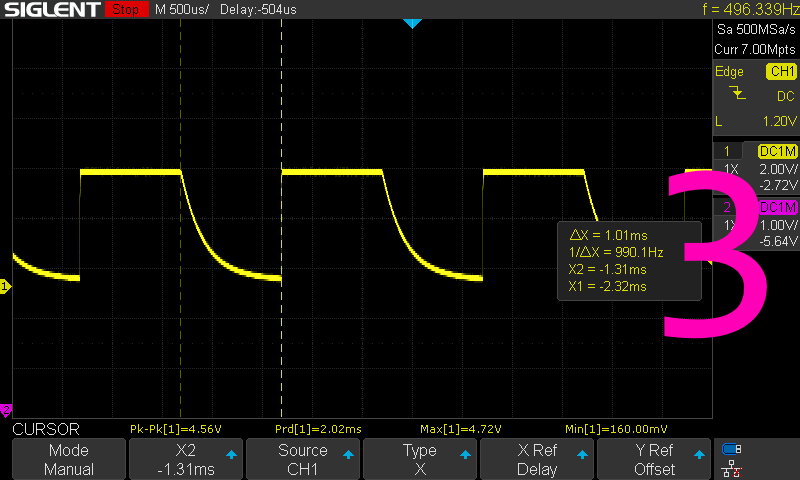
Oszilloskop-Messung eines Signals
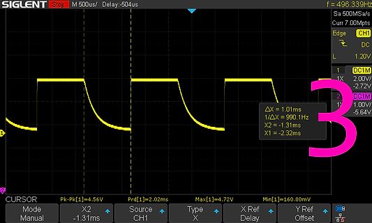
SIGLENT Stop M 500us/ Delay:-504us f = 496.339Hz Sa 500Msa/s Curr 7.00Mpts Edge CH1 DC L 1.20V 1 DC1M 2.00V 2 DC1M 1.00V -5.64V ΔX = 1.01ms 1/ΔX = 990.1Hz X2 = -1.31ms X1 = -2.32ms CURSOR Pk-Pk[1]=4.56V Prd[1]=2.02ms Max[1]=4.72V Min[1]=160.00mV Mode Manual X2 -1.31ms Source CH1 Type X X Ref Delay Y Offset
in „Probleme mit Gate-Treiber“ · Analoge Elektronik und Schaltungstechnik · · Oszi-Bilder
-
PDF
geld2_gesamt.pdf
64 Das Giralgeld Das Giralgeld 65 Geldmenge M1 Geldmenge M3 Zur Geldmenge M1 zählen das außerhalb des Bankensektors zirkulie- Die Geldmenge M3 beinhaltet neben der Geldmenge M2 noch weitere rende uneingeschränkt liquide Bargeld sowie täglich fällige
-
Datei
AT90S.txt
line nop ;Added by DC to bring up to 1 us for 4 mHz clock nop ;Added by DC to bring up to 1 us for 4 mHz clock cbi PORTB,3 ;OE low to clock in data swap temp1 ;get lower 4 bits andi temp1,0b11110000 ; mask off lower 4 bits, make OE and RS low sbr temp1,OE ;OE high out PORTB,temp1 ;write lower 4 bits to LCD ; nop ; nop nop ;Added by DC to bring up to 1 us for 4 mHz clock nop ;Added by DC to bring up to 1 us for 4 mHz clock ; cbi PORTB,3 ;OE low to clock
in „Hilfe zu Assemblerprogramm“ · Mikrocontroller und Digitale Elektronik ·
-
 Bild
Oszilloskop-Messung mehrerer Kanäle
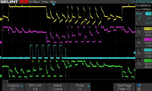
SIGLENT Stop M 100us/ Delay:-160us/ f = 5.55827kHz Sa Curr 3.50Mpts Edge DC L 1 1X 10.0V/ 23.6V 2 DC1M 1X 10.0V/ -1.0V 3 DC1M 1X 10.0V/ -17.4V 4 DC1M 1X 10.0V/ -36.4V CH2 Coupling BW Limit Adjust Probe Next Page Page 1/2
in „BLDC mittels ESC ansteuerung“ · Mikrocontroller und Digitale Elektronik · · Oszi-Bilder
-
 Bild
Oszilloskop-Messkurven
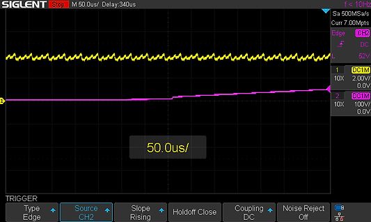
SIGLENT Stop M 50.0us/ Delay:340us f < 10Hz Sa 500Msa/s Curr 7.00Mpts Edge CH2 DC 1 10X 2.00V/ 0.0V 2 DC1M 10X 100V/ 0.0V 50.0us/ TRIGGER Type Edge Source CH2 Slope Rising Holdoff Close Coupling DC Noise Reject Off
in „Störungen von Relais (EMI) bringen I2C-Display/USB aus dem Takt“ · Mikrocontroller und Digitale Elektronik · · Oszi-Bilder
-
Datei
uhr.asm
.include "C:\PROGRA~1\VMLAB\include\m8def.inc" .def temp = r16;Temp .def temp1 = r17;Temp1 .def temp2 = r18;Temp2 .def temp3 = r19;Temp3 .equ adresse = 0x0060;Startadresse für LCD-Speicher im S-RAM .equ sekunde = 0x0090 .
in „Hex Wert -> Dezimal an LCD ausgeben“ · Mikrocontroller und Digitale Elektronik ·
-
Datei
LCD_Test_Mega32.asm
......................................................................; ;include dateien .include "m32def.inc" ;definitionen .ifndef XTAL .equ XTAL = 4000000 .endif ;R0-R15 ;temp register .def temp1 = R16 .def temp2 = R17 .def temp3 = R18 ;doubleword register .def dw0 = R19 .def dw1 = R20 .def dw2 =
in „LCD an mega32“ · Mikrocontroller und Digitale Elektronik ·
-
 Bild
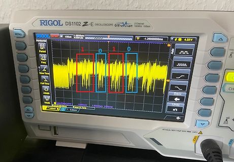
Rigol DS1102Z-E Oszilloskop mit digitalem Signal
RIGOL DS1102Z-E OSCILLOSCOPE UltraVision 100MHz 1GSa/s MENU STOP H 1.000GSa/s 100us 6.00M pts D -1.2500000ms Auto 1 0 1 0 Period Freq Rise Time Fall Time Width Width LowPassCH1 5.000mV 1.00M Sa/s 100Hz Period=60.00us Freq=16.1Hz 100V 5.00mV CH1 CH2
in „Bluetooth mit hoher Reichweite, nRF54-Samples, Logik-FPGAs und mehr“ · HF, Funk und Felder · · Fotos
-
 Bild
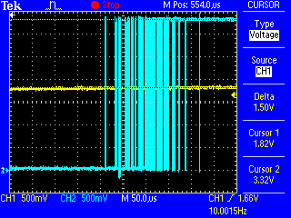
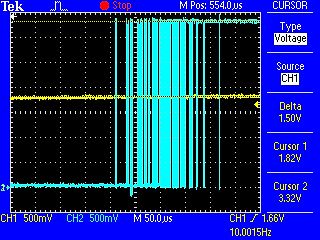
Oszilloskop-Messung eines digitalen Signals
Tek M Stop Pos: 554.0us Cursor Type Voltage Source CH1 Delta 1.50V Cursor 1 1.82V Cursor 2 3.32V CH1 500mV CH2 500mV M 50.0us CH1 1.66V 10.0015Hz
in „Handbetriebenen Drehgeber ohne Timer auswerten“ · Mikrocontroller und Digitale Elektronik · · Oszi-Bilder
-
Datei
thermo_little.c
5500; // Oberes Temp-Limit char status = 0x10; // Status für Schaltausgang char min_buffer[4] = {'M', 'i', 'n', 0x00}; char max_buffer[4] = {'M', 'a', 'x', 0x00}; char set_buffer[4] = {'S', 'e', 't' , 0x00}; void delay(unsigned int us) { while ( us ) us--; } unsigned int read_adc(unsigned char adc_number
in „Optimieren? Thermostat mit Tiny26“ · Mikrocontroller und Digitale Elektronik ·
-
Datei
uhr.asm
.include "C:\PROGRA~1\VMLAB\include\m8def.inc" .def temp = r16;Temp .def temp1 = r17;Temp1 .def temp2 = r18;Temp2 .def temp3 = r19;Temp3 .def counter = r20 .equ adresse = 0x0060;Startadresse für LCD-Speicher im S-RAM .equ
in „Hex Wert -> Dezimal an LCD ausgeben“ · Mikrocontroller und Digitale Elektronik ·
-
 Bild
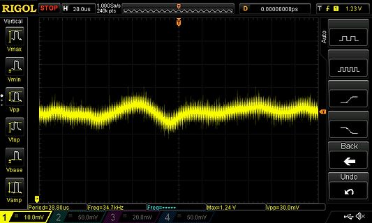
Oszilloskop-Messung eines Signals
RIGOL STOP H 20.0us 1.00GSa/s 0.00000000ps T 1.23V Vmax Vmin Vpp Vtop Vbase Vamp Period=28.8us Freq=34.7kHz Freq= Max=1.24V Vpp=30.0mV 1 10.0mV 2 50.0mV 3 20.0mV 4 50.0mV Auto Back Undo
in „Hilfe bei Spannungsversorgung für DVB-S2-NIM“ · Analoge Elektronik und Schaltungstechnik · · Oszi-Bilder
-
PDF
MOSFET-irfiz34v.pdf
, for 10 seconds 300 (1.6mm from case ) Mounting torque, 6-32 or M3 srew 10 lbf•in (1.1N•m) Thermal Resistance Parameter Typ. Max. Units RθJC Junction-to-Case ––– 5.0 RθJA Junction-to-Ambient ––– 65 °C/W www.irf.com 1 12/12
in „Frage zur Optokoppler“ · Mikrocontroller und Digitale Elektronik ·
-
PDF
409-13680-0-KS7212.pdf
Supply Voltage V - 4.75 5.0 5.25 V DD Input Voltage VIH - 0.7VDD - - V VIL - - - 0.3DD V Output Voltage 1 VOH1 IOH1=-2mA VDD0.5 - - V VOL1 ICL1=4mA - - 0.4 V Output Voltage 2 VOH2 ICH2=-4mA VDD0.5 - - V (CL, RG, SHP, SHD) VOL2 IOL2=3mA - - 0.4 V Output Voltage 3 VOH3 ICH3=-8mA VDD0.5 - - V (H1, H2, H3, H4
in „Türsprechanlage - wie anschließen“ · Mikrocontroller und Digitale Elektronik ·
-
PDF
EVQ4210-U-00B_r1.1_MPS.pdf
Load Transient V =12V , V =5V , Load=2.5A to 5A , V IN2V , V OUT=5V , Load=0A to 2.5A , IN OUT 150mA/us 150mA/us CH1: VOUT CH1: VOUT /AC /AC 200mV/div. 200mV/div. CH4: IUT CH4: IUT 2A/div. 2A/div. 1ms/div. 1ms/div. V IN2V , V OUT=20V , Load=0A to 2.5A, VIN12V , V OUT =20V , Load=2.5A to 5A, 150mA/us 150mA/us CH1: VOUT CH1: VOUT /AC /AC 500mV/div. 500mV/div. CH4: IUT CH4: IUT 2A/div. 2A/div. 1ms/div. 1ms/div. Input Voltage Transient, Input Voltage Transient, V INV to 20V , V OUT =15V , Load=0A V INV to
in „Controlling DC DC converter with STM32“ · Analoge Elektronik und Schaltungstechnik ·
-
PDF
ttester.pdf
N-JFET 1.1mA Vgs=.75V 1.1mA Vgs=0.75V 1.1mA Vgs=0.75V Idss=2-6mA BF245B N-JFET 2.5mA Vgs=1.7V 2.5mA Vgs=1.7V 2.5mA Vgs=1.7V Idss=6-15mA BF245C N-JFET 3.9mA Vgs=2.7V 3.9mA Vgs=2.7V 3.9mA Vgs=2.7V Idss=12-25mA
-
PDF
ttester.pdf
N-JFET 1.1mA Vgs=.75V 1.1mA Vgs=0.75V 1.1mA Vgs=0.75V Idss=2-6mA BF245B N-JFET 2.5mA Vgs=1.7V 2.5mA Vgs=1.7V 2.5mA Vgs=1.7V Idss=6-15mA BF245C N-JFET 3.9mA Vgs=2.7V 3.9mA Vgs=2.7V 3.9mA Vgs=2.7V Idss=12-25mA