jetzt nicht gedacht. Aber wenn man sich ein Datenblatt von einem spezifisschen Spannungsregler (z.B. 78L03) steht auch 30V maximum. Trotzdem nochmal danke
m.E. genug. FPgA chip XC2018: wie man sieht es ist trivial im Design. http://3.bp.blogspot.com/-L03SM-Uduto/UCng1py8nxI/AAAAAAAABiM/5BWB7TVe8j0/s1600/xc2018_overview.jpg VHDL,Verilog,Systemverligo,SystemC ist doch wurst oder. VHDL mag ich da es Formaler ist als Verliog. Mercedes, BMW &co :
großer schwarzer Fleck von den austretenden Kristallen. Der verbaute Screen ist ein 15,4 Zoll N154I3-L03 aus dem Hause Chi Mei mit einer Auflösung von 1280x800. Ich habe leider nichts genaues dazu gefunden, aber ich gehe davon aus, dass er die selben Spezifikationen hat wie dieser hier: 15,4 N154I1-L08
http://www.datasheetarchive.com/pdf-datasheets/Datasheets-25/DSA-497887.pdf )und als ersatz: M180E1-L03 (datasheet: http://www.pdfsea.com/down/down.php?downid=10232&id=0 , oben auf download datasheet) ich sehe bei den beiden displays ausser unterschiedlicher pinbelegung, anderer betriebsspannung und
rückseitig.l02 Projekt-Lötstoppmaske - vorderseitig.l07 Projekt-Platinenumrisse.l00 Projekt-Rückseite.l03 Projekt-Siebdruck - vorderseitig.l08 Projekt-Vorderseite.l06 [/code] Verwendest du Windows? (bzw. welches OS) Würde dir das Skript etwas bringen? Wenn dir so eine Automatisierung etwas bringt
Als Ersatz für den nicht existierenden 78L03 kann man einfach einen LM317 nehmen, braucht nur zusätzlich 2 Widerstände zur Spannungseinstellung. Allerdings wäre wohl ein Low-Drop Regler besser geeignet.
anderen Pin zum kontrolliert an/ausschalten. Versorgungsspannung ist sauber (6V Bleiakku und 78L03) und zusätzlich wurde der Data-Out des DCF77 mit 100nF gegen VCC gezogen, damit die Impulse sauberer Kommen. Laut OSZI schickt das DCF-Modul auch sauber die Impulse raus (vgl. DCF_high_bit und DCF_low_bit
Hintergrundbeleuchtung des Grundig Xephia 32 LXW 82-5500 TOP. Das Display ist von Samsung, LTA 320 W2-L03A und die Beleuchtungseinheit hat die Bezeichnung LTA 320 W2-L01(A). Das Inverterboard der Beleuchtung ist von TAIYO YUDEN, Korea und hat die Bezeichnung KLS-320VE-J Rev. 01 94V-0. Das Mainboard hat
dann ansteuern? ich hab das defekte display auseinander genommen. es handelt sich um ein LTN121W1-L03, diese nummer ist in den metall-rahmen des displays geprägt. nachdem ich die hintergrundbeleuchtung abmontiert habe, kam die glasplatte mit dem TFT zum vorschein. angesteuert wird diese durch eine platine
offenbar kommen zu viele "Neuerscheinungen" heraus. Identifizieren konnte ich bereits LTME = LTC2402I, L03A = LP2981... und L0SB = LP2985... Sachdienliche Hinweise sind jederzeit willkommen ;-)) Edith Der Oszillator für den TMS320VC5416 ist beschriftet mit CMAC.FN 3184FY. Damit komm ich auf der
40 dBm <-40 dBm This circuit can also be used for other frequencies; the values of C6, C7, C8, L01, L03 and the SAW resonator are changed accordingly Page 5 SAW CE AE PD SAW Components Application: Principles of SAWR stabilized oscillators Fig.4: Remote-control transmitter for 433.92 MHz Page 6 SAW CE
nicht SMD sind (30V...). Hier einige P-MOSFET, TO220, für Vgs=4,5V spezifiziert 40V: IPP120P04P4L03AKSA2 60V: SQP90P06-07L_GE3 SQP100P06-pM3L_GE3 SUP53P06-20-E3 SUP90P06-09L-E3
MOSFET mit maximal 10mOhm R-DS,ON einsetzen und als SMD verlöten. Beispiel: Infineon IPB80N03S4L-03 Gibts auch bei Digikey ab 1 Euro / Stück. Die Verlustleistung kann dann von der Platine aufgenommen werden. Schöner wäre noch der IPD90N03(...), der ist bei Digikey zwar aktuell gelistet,
H03 H04 H05 H06 H07 2 C10 V DIG1 11 L01 R R 1 E 100n R1 6 L02 LED3 D L U? 25.9k DIG2 74HCT244 DIG3 7 L03 D1 D2 D3 D4 D5 D6 D7 D8 R 7 3 L04 R DIG4 LED LED LED LED LED LED LED LED 2 GNDD DIG5 10 L05 GNDD 18 I_SET DIG6 5 L06 L00 2 C 18 1 8 L07 1A0 C 1Y0 DIN DIG7 H00 H01 H02 H03 H04 H05 H06 H07 4 1A1 V 1Y1
or-ing: A9 VBUS SBU2 B8 A9 VBUS SBU2 B8 short and reverse including EMC complianceith the Mornsun K78L03 switcher (high efficiency) D A12 GND D- B7 USB_PROG_N D A12 GND D- B7 USB_UART_N N B1 GND D+ B6 USB_PROG_P N B1 GND D+ B6 USB_UART_P USB XOR external power G B4 VBUS CC2 B5 G B4 VBUS CC2 B5 polarity
VCC_+3,3 VCC_+3,3 VCC VCC_+3,3 6 TS78L03CY 0 R 1 D1 VCC +3,3V 0 R 0 R 0 R IN OUT PD0 / LED 1 / TXD 4 4 4 N PD3 ______erPD6 / Taster 2 3 1N4001F + G n PA2 / RESEPB7 / SCK K 0 7 IC2 0 PB6 / Taster 3 / MISOter 3 / MOSI 1 C 1 C GND PD1 / LED 2
ld bc,0002h l0365: ld a,(0d175h) ld d,a ld a,(0cff1h) and 0f8h or d ld (0cff1h),a push bc di call l03a6 ei pop bc call l04db di call l03a6 ei call l03d7 pop bc ret l0386: ld a,(0d175h) ld d,a ld a,(0cff1h) and 0f8h or d ld (0cff1h),a push bc di call l03a6 pop bc call l04db call l03a6 ei call l03d7 pop bc ret l03a5: inc hl l03a6: ex de,hl ld hl,0cff3h ld b,(hl) ld (hl),0ah ld (hl),0eeh ld (hl),0bh ld (hl),0eeh ld (hl),0ch ld (hl),0ceh ld (hl),10h ld b,(hl) ld (hl),11h ld c,(hl) ld (0d1d7h),bc ld (hl),12h ld
adapted to the new company name where appropriate. PH7030L_4 20050307 Product data sheet - PH7030L-03 (9397 750 14206) PH7030L-03 20040304 Product data - PH7030L-02 (9397 750 12944) PH7030L-02 20030918 Product data - PH7030L-01 (9397 750 11946) PH7030L-01 20030502 Product data - - (9397 750 11405) PH7030L
PIR3602 IO_L01n_0_VREF P I U 4 0 C 4 4K87 0402 IO_L02p_0 P I U 4 0 B 2 IO_L02n_0 P I U 4 0 A 2 IO_L03p_0 P I U 4 0 D 6 GND GND IO_L03n_0 P I U 4 0 C 6 SW1 +3.3V IO_L04p_0 P I U 4 0 B 3 PISW101 PISW108 IO_L04n_0 P I U 4 0 A 3 PISW102 PISW107 IO_L05p_0 P I U 4 0 B 4 PISW103 PISW106 IO_L05n_0 P I U 4 0
and are intended for configuration values, so you can use functions 01 or 02 to read any registers. l 03(0x03) Read Device Data DTU or microinverter data registers are generally read-only and report voltage, current, power, energy, and related values. l 05(0x05) Write Single/All Device Status This writes
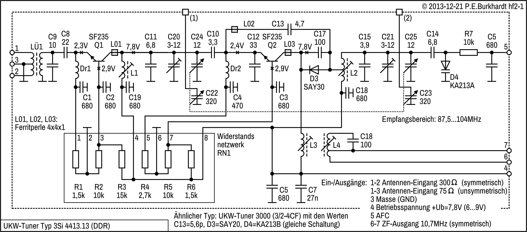
frequency of 88 MHz the LOC OSC tuning voltage V TUN is set to 2.58 V with L04. The prestage coils L01 and L03 have to be adjusted to maximum signal strength. At 106 MHz maximal signal strength is set with P01. Wireless Products 2000-07-21 PAGE: 11 TUA 4401K CAR RADIO At the balanced mixer output (pins 25 and
DETAIL B : PALLADIUM PACKAGE STRUCTURE PACKAGE MATERIAL EPOXY RESIN SOLDER/PALLADIUM SONY CODE SOP-8P-L03 LEAD TREATMENT PLATING EIAJ CODE SOP008-P-0225 LEAD MATERIAL 42/COPPER ALLOY JEDEC CODE PACKAGE MASS 0.1g NOTE : PALLADIUM PLATING This product uses S-PdPPF (Sony Spec.-Palladium Pre-Plated Lead Frame
F 20.6 P E 19.7 O O K P (12.3) 6.4 ±0.8 T N T A C 5 T 4 9 5 1 4 6 1 5 - _< 5 6 8 9 S ( H I W S O T L03: straight lever L41: adjustable plastic lever A P 191.071.101 190.075.013 N S S E C I j F 18.6 S (12.3) O j P L 3.8 T (12.3) 4.8±0.8 P F N P O I ø5 T - ) R 0 0 . I . 6 2 ( 5 5 M ) 1 1 – 6 . 9 1 1 (

 Bild

 Bild
 Bild

 Bild

 Bild

 Bild