connected toSS : BS0, BS2, CL, D[7:3], E, R/W#, CS#, D/C#, BGGND, LS Pin internally connected toDD : BS1, CLS VBAT, C1P, C1N, C2P, C2N, FR should be left open. C1, C2: 2.2uF (1) C3: 1.0uF (1) RP: Pull up resistor Voltage at I = V – 3V. For V = 12V, I = 30uA
connected toSS : BS0, BS2, CL, D[7:3], E, R/W#, CS#, D/C#, BGGND, LS Pin internally connected toDD : BS1, CLS VBAT, C1P, C1N, C2P, C2N, FR should be left open. C1, C2: 2.2uF (1) C3: 1.0uF (1) RP: Pull up resistor Voltage at I = V – 3V. For V = 12V, I = 30uA
9EUR). Beim Bestellen des MC sollte man einen CAN-BUS-Treiber gleich mitbestellen: z. B. Philips PCA82C250. Jedoch auf vorhandene Versorgungsspannungen achten (AT90CAN128 "kann mit" VCC=2,7...5,5V, PCA82C250 lt. Datenblatt für VCC=4,5...5V). CANopen software protocol stacks at Freier CANopen stack: <!-
bis zu 512k flash und 96k RAM Luminary Micro Stellaris LM3S8xxx. ARM Cortex-M3 bis 64kByte RAM und 256kByte Flash CAN und Ethernet Microchip PIC18Fxx8 PIC18Fxx8x. Mikrocontroller mit CAN Schnittstelle Herstellerseite Mitsubishi / Renesas R8C / M16C / M32C. R8C/23, M16C/6Nx Motorola / Freescale DSP56F8xx
above 25⋅C at the following rates: D-14 package at 7.8mW/⋅C D-8 package at 6.3mW/⋅C N-14 package at 11.5mW/⋅C N-8 package at 9.3mW/⋅C April 15, 1992 251 Philips Semiconductors RF Communications Products Product
The history of the NXP Hitag2 family of transpon- munication can be intercepted over a distance of at least ders overlaps with that of other security products de- 100 meters. signed and deployed in the late nineties, such as Kee- 1http://www.nxp.com/products/automotive/ loq [ 8, 13, 27, 28], MIFARE Classic
ab. https://www.spiegel.de/ausland/china-humanoide-roboter-zeigen-kung-fu-im-staatsfernsehen-a-746c4dec-ac7c-437d-ba39-6934f04b1a18
Michael K. schrieb im Beitrag #8017995: > Nur das C3PO nicht Rücken bekommt und dann KK und Staat noch ne Mio > kostet bis er sich zu Tode säuft. Kauft der C3PO auch einen Kleinwagen? Wenn also alle Produktiv leistenden Arbeitende von C3PO Kopien
VSVN H U H U |R12 47 OBLJ_ J l470B ) H Christian Lotter KG Datensysteme SER|EL1 |[ CENTRONICS & - _ C19 «7° ) ' " n- * Z10 Z27 |i7l Z 28 LS244 " tJ. C23 751» 96 ' 6 1 6 4 ' 6164 'LS2S» pol O MZ1 VS l, Z 24 1041. Z 25 10' 1 Z M Z30 616c «164 LS 251 VDC 6845 Z 3l ^H %- C^ h C'^H % - CÜ4J- NE55S . Z72 (
±.10] c No. of Dimensions Part Numbers I Positions A B C 15.24 Centerline g 25.10 27.94 30.48 r 24 .988 1.100 1.200 390263-7 e i 28 30.12 33.02 35.56 390263-1 n 1.190 1.300 1.400 E 32 35.20 38.10 40.64 390263
ultrasonic vibrations should not be used for post-solder cleaning to avoid damaging the crystal. 3. For SOH28 package, lead-free (Pb-free) lead finish: reflow at peak temperature of 260°C (the time above 255°C must not exceed 30 seconds). Caution: Negative undershoots below –0.3 V are not allowed on any pin
visibility will always be more than 10 meters. The ambient temperature must always be between -5° C and +45° C. Keep away from direct insulation (particularly in cars) and heaters. The relative humidity must not exceed 50 % with an ambient temperature of 45° C. This device must only be operated in
transmitted as a one if the operating voltage has dropped below the low voltage trip point, typically 3.8V at 25°C. This Vsignal is If the supply voltage drops below the low voltage trip transmitted so the receiver can give an indication to the point, the LED output will be toggled at approximately user that
meinem LA zb. angeschaut mit welcher Geschwindigkeit und Länge bei dem China USB/Akku Lötkolben die C210 spitzen Betrieben werden. Nun hab ich das ganze mit 17Ah aus 20 Akkuzellen der Vapes (850mAh) einem Puya PY32F030K28 und Display der Vapes + Drehgeber als Akkulötkolben zusammengefrickelt. Ging mir
Garnicht so übel. Mein AtMega8535 wollte einfach nicht so richtig bei TWI. Und Fehler in Google eingegeben, KI Antwort: Zitat: "...Nutzen Sie innerhalb von i2c_write für die TWI-Steuerung und die Warteschleife ein anderes
Pressemitteilung folgendermaßen beschrieben wird: [c] Key SuperFlash performance and reliability metrics for UMC’s 28HPC+ ESF4 AG1 platform include: • Automotive Electronics Council (AEC) Q-100 Grade 1 qualified for operating temperatures of -40°C to +150°C (Tj) • Read access time < 12.5ns • 100K+ endurance cycles • Data retention of > 10 years @ 125°C • Only 1-bit ECC required • Qualification of 32Mb macro at auto grade
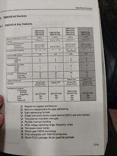
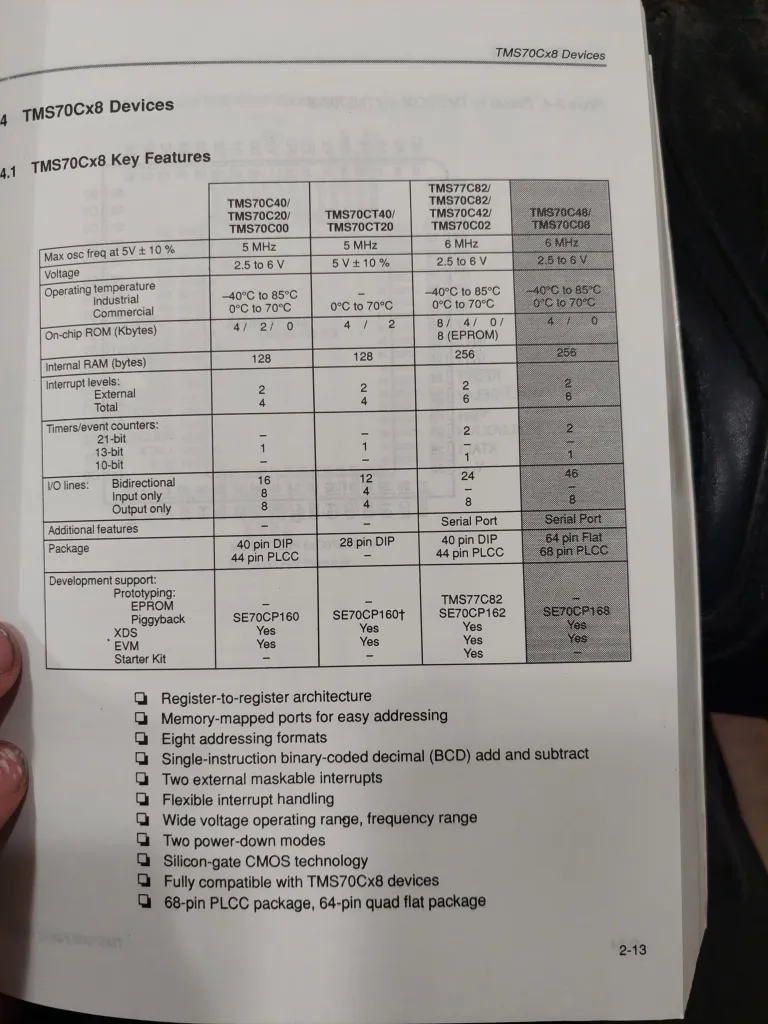
TMS70Cx8 Devices
4.1 TMS70Cx8 Key Features
TMS70C40/TMS70C20/TMS70C00
Max osc freq at 5V ± 10%
5 MHz
Voltage
2.5 to 6 V
Operating temperature
Industrial
Commercial
-40°C to 85°C
0°C to 70°C
TMS70CT40/TMS70CT20
5 MHz
5V ± 10%
128
Internal RAM (bytes)
128
256
256
TMS70C82/TMS70C82/TMS70C42/TMS70C02
6 MHz
2.5 to 6 V
-40°C to 85°C
0°C to 70°C
TMS70C48/TMS70C08
6 MHz
2.5 to 6 V
-40°C to 85°C
0°C to 70°C
Interrupt levels:
External
Total
2
6
2
6
2
6
2
6
I/O lines
einen ordentlichen Stack. > So eigentlich nur ASM möglich. > > Ich erwarte von einem modernen µC, dass man ihn in C++, wenigstens mit C > Programmieren kann. Die meisten haben keinen Stack. Aber Ram. Den Rest regelt der C-Compiler, der ein paar Restriktionen bei Funktionspointern hat und rekursive
analog-to-digital converters (ADCs) with up to 17 external channels • 14-bit effective resolution at 250ksps with hardware averaging • One 12-bit 1Msps digital-to-analog converter with integrated output buffer (DAC) • Two zero-drift zero-crossover chopper op-amps (OPA) – 0.5µV/°C drift with chopping
/components/esp_timer/src/esp_timer_init.c:28 D (356) cpu_start: calling init function: 0x420075f6 on core: 0 --- 0x420075f6: __esp_system_init_fn_init_libc at C:/Users/localuser/esp/v5.5.1/esp-idf/components/newlib/src/init.c:12 D (362) cpu_start
cpu_start: calling init function: 0x420003a0 on core: 0 --- 0x420003a0: __esp_system_init_fn_init_efuse at C:/Users/localuser/esp/v5.5.1/esp-idf/components/efuse/src/esp_efuse_startup.c:158 D (416) efuse: BLK0 REG2 [24-27], len=4 bits D (420) efuse: BLK0 REG2 [28-31], len=4 bits D (424) efuse: BLK0 REG3
applied to theTVS without operation V Breakdown Voltage -- Maximum voltage that flows though theTVS at a specified test current (I ) BR T V Clamping Voltage -- Peak voltage measured across theTVS at a specified Ippm (peak impulse current) C IR Reverse Leakage Current -- Current measured at V R VF Forward
Support: Let’s discuss integration with your projects and explore zero-redesign drop-ins now. [/c] ### STMicroelectronics ISM6HG256X - IMU mit zwei simultan aktiven Messbereichen Dass IMUs eine „umschaltbare“ Empfindlichkeit aufweisen, ist per se nicht neu. STMicroelectronics lanciert nun einen
und hohen g-Werten (±16g bzw. ±256g) im Verbund mit einem leistungsfähigen und stabilen Drehwinkelgeber (Gyroskop). [/c] ### ic-Haus iC-MBE - BiSS-Transceiver mit SPI-Interface Das BISS-Protokoll hat sich insbesondere im Bereich
(RoHS Compliant) Pin Configuration ISL88731 Applications (28 LD TQFN) TOP VIEW • Notebook Computers • Tablet PCs P N T T S N S S C O G H C • Portable Equipment with Rechargeable Batteries C C V B U P D 28 27 26 25 24 23 22 Ordering Information NC VDDP 1 21 PART
to 10 ±8 g FS bit set to 00 1024 LSB/g So Sensitivity FS bit set to 01 512 LSB/g FS bit set to 10 256 LSB/g TCSo Sensitivity change vs. temperaturFS bit set to 00 ±0.01 %/°C Tyoff Typical zero-g level offset accuracy ±80 mg Tcoff Zero-g level change vs. temperatuMax delta from 2C° ±0.6 mg/°C FS bit
event pending flag, set by H/W at INT2 pin’s falling INT2IF 0C.2 R - edge W 0 write 0: clear this flag; write 1: no action R - INT1 (PA1) interrupt event pending flag, set by H/W at INT1 pin’s INT1IF 0C.1 falling/rising edge W 0 write 0: clear this flag; write 1: no action INT0 (PA3) interrupt event pending flag, set by H/W at INT0 pin’s INT0IF 0C.0 R - falling/rising edge W 0 write 0: clear this flag; write 1: no action INTIE1 (0Dh) Function related to: Interrupt Enable All port pin change wakeup interrupt enable PCIE 0D.6
event pending flag, set by H/W while WKT time out WKTIF 0C.3 W 0 write 0: clear this flag; write 1: no action R - INT2 (PA7 or PB5) interrupt event pending flag, set by H/W at INT2 INT2IF 0C.2 pin’s falling edge W 0 write 0: clear this flag; write 1: no action INT1 (PA1 or PB1) interrupt event pending flag, set by H/W at INT1 INT1IF 0C.1 R - pin’s falling/rising edge W 0 write 0: clear this flag; write 1: no action R - INT0 (PA3 or PB2) interrupt event pending flag, set by H/W at INT0 INT0IF 0C.0 pin’s falling/rising
Bestücker ein Problem damit haben. Der IS31 wirkt etwas rustikaler, braucht aber nur ein einziges Abblock-C. Die 9 Ausgänge liefern Konstantstrom, das spart die Widerstände und man kann die Helligkeit in 256 Stufen einstellen, auch ohne PWM. Die Daten kommen per I2C rein, das kostet leider 4 Adern, dafür
Bei D2 handelt es sich um eine TVS Diode, welche auch gleich als Verpolschutz dient. Sie beginnt bei 28V zu arbeiten. Bei 34.4V arbeitet sie zuverlässig und schützt somit den Spannungsregler, welcher bis 36V verwendet werden darf. C5,C6 dienen als Pufferung der 12 bzw. 24V. Sie sind für maximal 50V
PCA9532 2 16-bit I C-bus LED dimmer Rev. 4.1 — 22 August 2016 Product data sheet 1. General description The PCA9532 is a 16-bit I C-bus and SMBus I/O expander optimized for dimming LEDs in 256 discrete steps for Red/Green
3.34 n 510 V e T q 505 U 3.32 r 500 V F 3.30 n 495 OUT= 15 mA h t 490 3.28 w OUT = 50 mA S 485 3.26 480 -40 -25 -10 5 20 35 50 65 80 -40 -25 -10 5 20 35 50 65 80 Ambient Temperature (°C) Ambient Temperature (°C) FIGURE 2-8: 3.3V V OUT vs. Ambient FIGURE 2-11: F OSC vs. Ambient Temperature. Temperature. 3.40 4.5 T A 85°C OUT = 5 mA 4 VOUT= 5.0V 3.36 3.5 3 ) 3.32 T A 25°C ) VOUT= 3.3V ( ( 2.5 U I O 3.28 V 2 VOUT= 2.0V V TA= - 40°C 1.5 3.24 1 0.5 3.20 0 0.8 1.2 1.6 2 2.4 2.8 0 1 2 3 4 5 6 7 8 9 10 V (V) I (mA) IN OUT FIGURE
enters 2·C 1∆t·V (c = 0)+I (c = 0) at position 1 of the right-hand side vector. Note thct I (t = 0) is zero because the voltage V1is applied at t = 0. Finally, the complete matrix equation writes as follows.
playback of a track Play track "0001" in the specified folder in a folder that supports 7E FF 06 14 00 C0 01 FE 26 EF 7E FF 06 14 00 C0 01 EF “12” 3000 tracks Play track "0255" in the specified folder 7E FF 06 14 00 C0 FF FD 28 EF 7E FF 06 14 00 C0 FF EF “12” Play track "1999" in the specified folder 7E
R R E R N Z R R E E E D S C E + + + E LMT_OLV C253 C256 C267 _ _ C _ _ _ E _ L L B Y L 5 _ C S _ _ _ R _ C C _ U P R _ S O _ I _ _ T P I U _ _ L L L S R S L 5 C C _ O C C O O S S R A P S 2 M O N C E M _ I O O P C _ _ N _ M D _
which is incremented at each request. - It can also be judiciously used as a smart index or pointer to identify a transaction context in order to memorize the current remote server and the pending MODBUS request. Normally,
characters CPT8 = CPT8 + 1 number characters charactererror un e3 characters sil nce YES error on at least NO 1 frame character YES length NO < 3 bytes YES NO CRC incorrect C P T 2 = C P T 2 + 1 C P T1 = C P T 1 + 1 YES NO slave number = 0 or YES slave NO slave number = my slave CPnumber 04 + 1 number
Jens M. schrieb im Beitrag #7942081: > von 32kB auf 256kB nicht passt, Der Arduino Mega hat 256k Flash.
// Blank for (uint8_t byte x = 0; x < 14; ++x) { ... [/c] Und was sind eigentlich diese magischen Zahlen 14 und 28? Arraylängen? Und warum wird das alles in setup() gemacht?
on the future of the struggling U.S. chipmaker. Nvidia will purchase Intel shares at $23.28 each, subject to regulatory approvals and closing conditions. [/c] Böse ist, wer in diesem Zusammenhang eine „Umkehr“ der Zusammenarbeit zwischen AMD und ATI andenkt. Nun haben beide CPU-Hersteller
erreichbaren Datentransferrate an. Außerdem hebt man in der Ankündigung die folgenden Features hervor: [c] PCIe 8.0 Specification Feature Objectives: • Delivering 256.0 GT/s raw bit rate and up to 1.0 TB/s bi-directionally via x16 configuration • Reviewing new connector technology • Confirming
eingehalten werden und ist der Grund, warum SP-Zugriffe im folgenden Code keine IRQ-Sperren brauchen: [c] void fun (int*); void bar (void) { int x[20]; fun (x); }[/c] [c] bar: push r28 push r29 in r28,__SP_L__ in r29,__SP_H__ sbiw r28,40 out __SP_L__,r28 out __SP_H__,r29 /* prologue: function */ movw r24,r28 adiw r24,1 call fun /* epilogue start */ adiw r28,40 out __SP_L__,r28 out __SP_H__,r29 pop r29 pop r28 ret [/c] > Für normale 16 Bit Variablen gilt das natürlich nicht.
2 R257 R258 6 R282 5 3 1 2 4 C263 C 3 R L217 D R255 R256 C221 5 2 C354 R 7 8 R I 3 0 R200 D C355 C382 2 2 R226 T4 C332 2 2 4 R203 D Q213 C379 9380 C391 L L R225 Q232 Q231 1 C C 3 R347 Q214 Q225 R449 1 3 3 4 C402 D R PF60 R348 R R
(__AVR_AT43USB320__) # include <avr/io43u32x.h> #elif defined (__AVR_AT43USB355__) # include <avr/io43u35x.h> #elif defined (__AVR_AT76C711__) # include <avr/io76c711.h> #elif defined (__AVR_AT86RF401__) # include
'A' put USART1_TXDATAL,tmp0 ldi tmp0,'B' put USART1_TXDATAL,tmp0 ldi tmp0,'C' put USART1_TXDATAL,tmp0 ldi tmp0,'D' [/avrasm] bringt "AB" auf einem AVR128DB28; übrigens genauso wie auf einem AVR128DA28, obwohl in dessen aktuellem Datenblatt unter '25.2 Overview'
put USART1_TXDATAL,tmp0 > ldi tmp0,'B' > put USART1_TXDATAL,tmp0 > ldi tmp0,'C' > put USART1_TXDATAL,tmp0 > ldi tmp0,'D' > [/avrasm] > bringt "AB" auf einem AVR128DB28; übrigens genauso wie auf einem > AVR128DA28, obwohl in dessen aktuellem Datenblatt unter '25.2
Hier das ganze auf einem AT89C2051 in Assembler: [avrasm] mov dptr, #table main: mov a, p1 movc a, @a+dptr mov p3, a jmp main table: val set 0 rept
Peter D. schrieb im Beitrag #7931621: > Hier das ganze auf einem AT89C2051 in Assembler: Vielen Dank für deine (hier vergebliche) Mühe. Aber in der simulierten Welt in der ich mich mit dem Problem befasste, müsstest du dir deinen AT89C2051 auch ersteinmal aus einzelnen
TBU device remains in the protected state of very low current TBU CCUURRREVVOOLLTTAAGGEE and voltage at the load. LIMIT DISCON ECTT LOAD S 1 3 V source e t o 4 v Figure 2. TBU device functional block diagram V load out 2 n nanosecond r reaction time c I op ~1µsec leak time Figure 4. TBU device reaction
hierarchical schematics as building blocks. You can get it here: Media:HierarchicalSchematicsAsBuildingblocksAtKiCad_RevC-EN_06May2015.pdf Eine Sammlung von gängigen Schaltungen mit den Längstreglern LM317 /LM78xx /LM79xx und dem Timer 555, die nach dem in obig erwänten Dokument KiCad_HierarchischeSchaltplaene
Epcos und Myrra sind auch dabei. Eurokartenstecker/-buchsen DIN 41612 Typ B1, B2, C1, C2 und C3. Ebenfalls enthalten: GNU-GPL und Creative Commons Symbole. Dazu Messpunkte. BNC-Buchse, Quarzoszillator, SMD Widerstände und Kondensatoren. (0805, 1206, 2512) sowie experimentelle Universalfootprints

 Bild
Bild