Verwendung) SFF > 73 % PFD 2) 4,69x10⁻⁴ AVG MTBF 3) 263 Jahre Sicherheitsfunktion4) Überwachung min max Bereich λ 26 FIT 101 FIT 117 FIT sd λ 165 FIT 165 FIT 165 FIT su λ dd 108 FIT 33 FIT 17 FIT λ du 107 FIT 107 FIT 107 FIT 1gemäss Kapitel 11.4.4 der IEC 61511-1 2der Wert ist nach ISA S84.01 und IEC
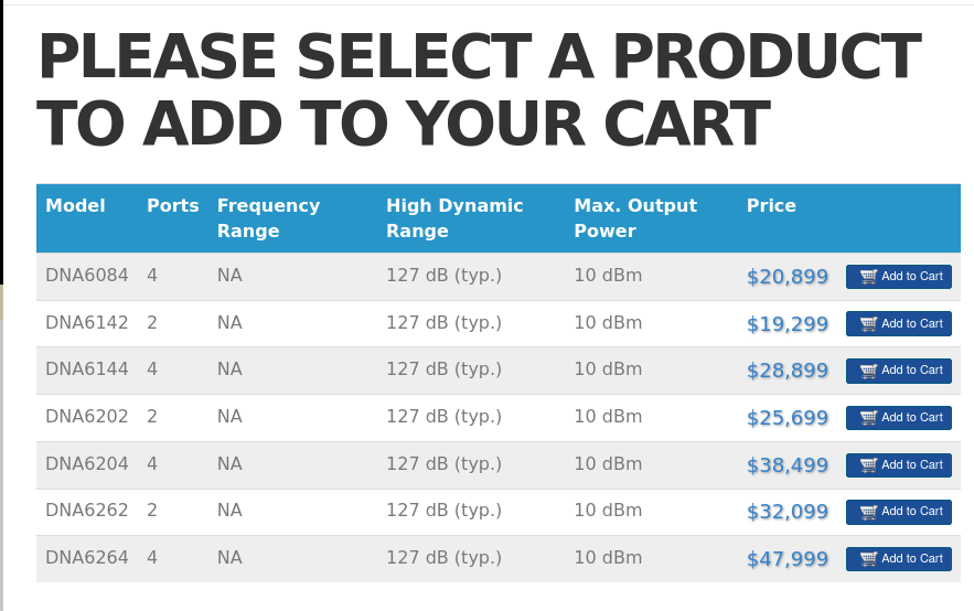
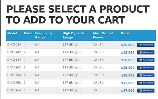
PLEASE SELECT A PRODUCT TO ADD TO YOUR CART
Model Ports Frequency Range High Dynamic Range Max. Output Power Price
DNA6084 4 NA 127 dB (typ.) 10 dBm $20,899 Add to Cart
DNA6142 2 NA 127 dB (typ.) 10 dBm $19,299 Add to Cart
DNA6144 4 NA 127 dB (typ.) 10 dBm $28,899 Add to Cart
DNA6202 2 NA 127 dB (typ.) 10 dBm $25,699 Add to Cart
DNA6204 4 NA 127 dB (typ.) 10 dBm $38,499 Add to Cart
DNA6262 2 NA 127 dB (typ.) 10 dBm $32,099 Add to Cart
DNA6264 4 NA 127 dB (typ.) 10 dBm $47,999 Add to Cart
TO CART
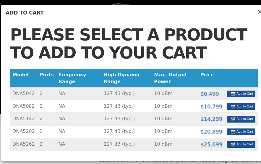
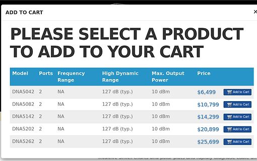
PLEASE SELECT A PRODUCT TO ADD TO YOUR CART
Model Ports Frequency Range High Dynamic Range Max. Output Power Price
DNA5042 2 NA 127 dB (typ.) 10 dBm $6,499 Add to Cart
DNA5082 2 NA 127 dB (typ.) 10 dBm $10,799 Add to Cart
DNA5142 2 NA 127 dB (typ.) 10 dBm $14,299 Add to Cart
DNA5202 2 NA 127 dB (typ.) 10 dBm $20,899 Add to Cart
DNA5262 2 NA 127 dB (typ.) 10 dBm $25,699 Add to Cart
Classification Reflow Profiles Profile Feature Specification* Average Ramp-Up Rate (tsmax to tP) 3°C/second max. Temperature Min (Tsmin) 150°C Pre-heat: Temperature Max (Tsmax) 200°C Time (ts) 60-180 seconds Temperature (T L 217°C Time maintained above: Time (tL) 60-150 seconds Peak/Classification Temperature
Joachim B. schrieb im Beitrag #8014902: > Tatsache bleibt, viele Arduinos LIBs zählen I²C bis 127, Nicht eher alle? Da die meist zu Grunde liegende Wire das eben auch so tut. Und laut dem NPX Dokument ist die Sichtweise auch voll ok so. 7 Adressbit und ein R/W Bit. Das R/W Bit liegt im
wäre es als Zitat gekennzeichnet gewesen. > Tatsache bleibt, viele Arduinos LIBs zählen I²C bis 127, R/W Bit > ausgeblendet ... I²C Adresse bis 127 entspricht der I²C-Spezifikation. NXP (damals noch Philips) hat das 1982 mit Einführung des Bus so festgelegt. Da ist kein Bit ausgeblendet. Um 10
129,6 hz Kann man sich doch fertig runterladen: https://tunebat.com/Info/Calm-the-Mind-Theta-127-5Hz-133-7Hz-sweetHz/36m2aKkAwzBj97SEWy2NZX
https://assets.nexperia.com/documents/data-sheet/74HC40103.pdf Achtung, die HC-MOS geht nur bis max. 6V Betriebsspannung, die alte bis >15V. CP clock-pulse ist der Eingang vom Quarzoszillator kommend, /TC und /PE verbunden sind der Ausgang, /PL und /MR müssen auf Plus, /TE auf GND.
ersichtlich allen gängigen Formaten bis 50,8 x 61 cm erhältlich. Für Fachvergrößerungen sind Breitrollen (127 cm breit) lieferbar. (entfällt bei papierstarken Sorten wie MULTICONTRAST CLASSIC 1 und RECORD-RAPID 1). Sonderformate sind auf Anfrage erhältlich. .1. = weiße Papierfärbung Bei den Abmessungen / Maßen
H2 I H 1 L 0 - 40 0 55 85 125 150 P d Tamb(°C) Note • Zero power is considered as measuring power max. 1 % of max. power. PHYSICAL DIMENSIONS FOR RELEVANT TYPE (all dimensions in millimeters) H1 R25VALUE BMAX. d H2 MAX. L P T MAX. MIN. MAX. 3.3 to 220 5.0 0.6 ± 0.06 1.0 4.0 6.0 24 ± 1.5 2.54 4.0
noch eine ganze Menge weiterer Platinenanschlüsse. Steckt da was drauf, wo geht das hin? Das Teil 127 Air Break, wofür ist das? Ist das nur eine Spule, oder gibt es eine Rückmeldung? Gibt es einen Trocknertimer, der vielleicht auf Null Minuten steht?
Habe lange überlegt, ob ich mich zu max707 vorletztem Posting (https://www.mikrocontroller.net/topic/583257?goto=8005613#8005562) äußern soll. Nur so viel, lieber Max: Ich empfinde Dein Posting schon als etwas "herabkanzelnd" und daher
between pins TX1 and TX2 at 13.56 MHz. [7] DD(SVDD)depends on the load at pin MFOUT. Vmod V V i(p-p)(max) i(p-p)(min) VMID 13.56 MHz carrier 0 V 001aak012 Fig 24. Pin RX input voltage range 14.1 Timing characteristics Table 154. SPI timing characteristics Symbol Parameter Conditions Min Typ Max Unit WL
e 7.5 2128.5 i200-240 Vac Normal Duty Heavy Duty NT-207 S +/- 10% 3Ø NT-212 12.5 37.5 e(kW@220 V, Max Motor Typical Max Motor Typical NT-320 20 569 r HP@230 V) Continuous Power Output Continuous Power Output F Order Code Current (A) (HP) (kW) Current (A) (HP) (kW) 1 10 100 ContinuousStall(lb-inPeak
: Formal 40h, realistisch 50h-55h Ü.-Stunden : abgegolten Urlaub : 30d Gehalt : 127k fix + 11k variabel (0-200%) + 6k BaV Entwicklung : Einstieg 2014 mit ca. 55k und 35h Vertrag, diverse ERA Stufenaufstiegen durch Positions- und Ortwechsel innerhalb des Konzerns. Seit 2024 AT. -
hält ihr ein Berufsoldat zu werden? Realistisch ist nicht Berufssoldat, sondern sich länger (max. 12 Jahre, eher 2-5 länger) zu verpflichten und das wegen der guten Ausbildung (auch Studium mit Ingenieurspatent). So hat sich beispielsweise der bekannte Sportarzt Hans-Wilhelm Müller-Wohlfahrt
Kopfspiegef an der Lehre anliegt, dund sor dern- gentstärkeregfer an Kgemessen. (Steckerleiste) ge- max. Abstand von 0,1 mm eingehalten uird. lvlassnach lvlS1 Uiedergabe-Pegelkontrolle bei geschlossenem Deckel uiederho.Ien. b) Kopfhöhe Der AIJL-Kopf uird mit der gleichen Lehre so ein- gestellt, daß die
H2 I H 1 L 0 - 40 0 55 85 125 150 P d Tamb(°C) Note • Zero power is considered as measuring power max. 1 % of max. power. PHYSICAL DIMENSIONS FOR RELEVANT TYPE (all dimensions in millimeters) H1 R25VALUE BMAX. d H2 MAX. L P T MAX. MIN. MAX. 3.3 to 220 5.0 0.6 ± 0.06 1.0 4.0 6.0 24 ± 1.5 2.54 4.0
) 0° Operating temperature (drive case max °C) 60° † 20°C per hour max (operating) Temperature gradient 35°C per hour max (non-operating) Relative humidity 5% to 95% (operating) 5% to 95% (non-operating) Relative humidity gradient (max) 30%
span Frequency Axis Linear or Log Averaging Displays The following average displays are available: Max Hold Min Hold Average Type of Averaging Exponentialonly Cursorfunctions Number of Cursors One or Two Cursor Modes The following cursor modes are provided: Continuously displayed amplitude and frequency
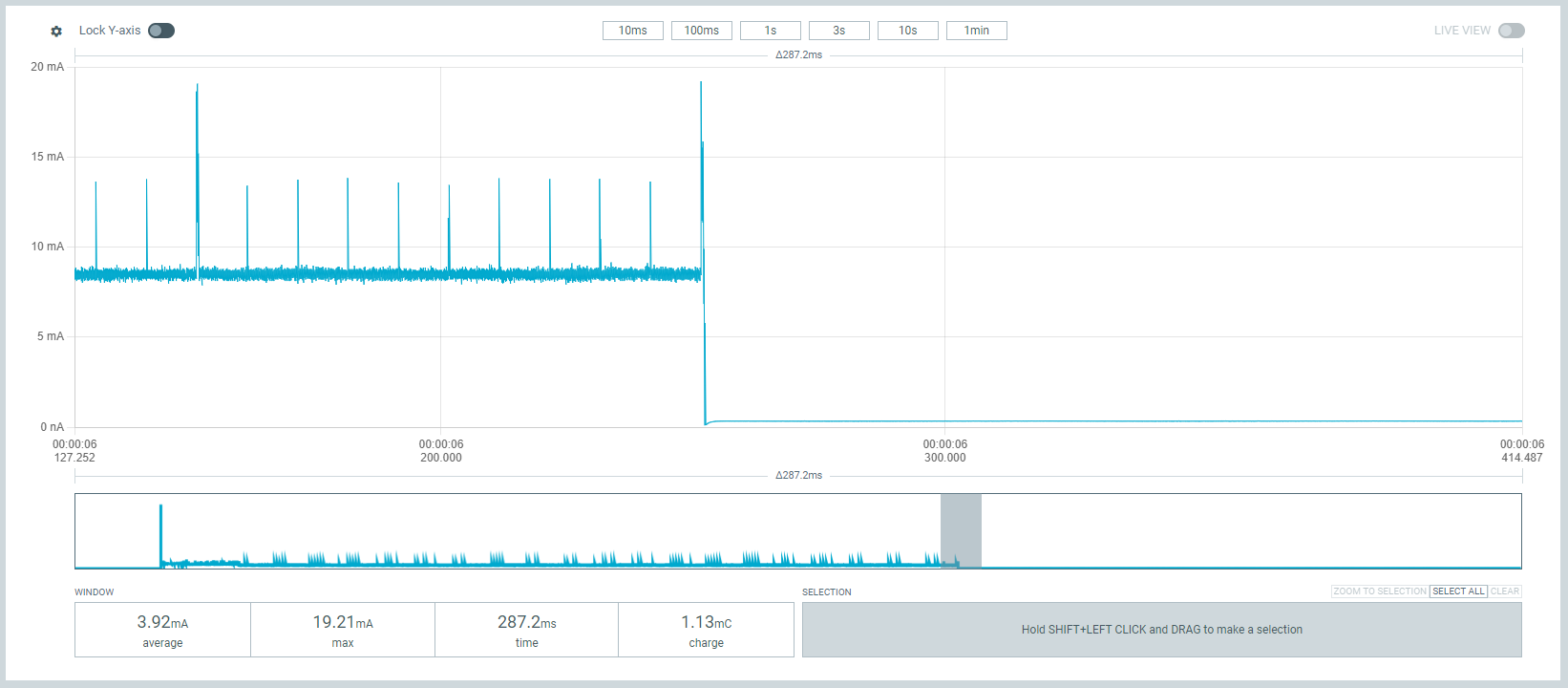
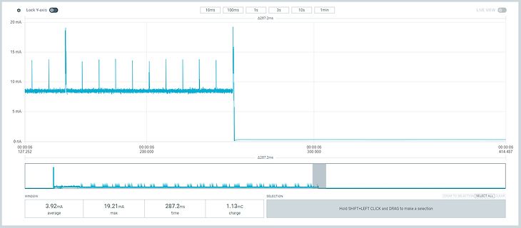
Lock Y-axis 10ms 100ms 1s 3s 10s 1min LIVE VIEW 20 mA Δ287.2ms 15 mA 10 mA 5 mA 0 nA 00:00:06 127.252 00:00:06 200.000 00:00:06 300.000 00:00:06 414.487 Δ287.2ms WINDOW SELECTION ZOOM TO SELECTION SELECT ALL 3.92mA average 19.21mA max 287.2ms time 1.13mC charge Hold SHIFT+LEFT CLICK and DRAG to
Siliconix SPECIFICATIONS (T = 25 °C, Cnless otherwise noted) PARAMETER SYMBOL TEST CONDITIONS MIN. TYP. MAX. UNIT Static Drain-source breakdown voltage V DS VGS = 0, D = 250 μA 60 - - V Gate-source threshold voltage V GS(th) VDS = VGS, D = 250 μA 2 3 3.5 Gate-source leakage I V = 0 V, V = ± 20 V - - ± 100
EV083(1).docx of JHLin 0.84 Aug, 2023 0.85 Aug, 2023 1. Modify the timing diagram of ADC 1. Modify Max. value of Total Accuracy and Integral Non-Linearity of ADC Electrical Characteristics 2. Add the table of “EEPROM Characteristics” 3. Add subsection for the section of “PWM Trigger ADC” 4. Add description
. 28 mm Bandbreite: min. 10 mm max. 400 mm Strip width: min. 10 mm max. 400 mm AnzahStreifenlänge: enen Lmin. 20 mm ser: max. 3000 mmmax. 3 NumbStrip length: t diamemin. 20 mm max. 3000 mm max. 3 Materialstärke 0,27 / 0,30 / 0,35 / 0,50
used to model the transmission characteristic of operational amplifiers. I = 0 I = 0 (11.4) 1 3 V2= V max ·2 arctan π ·G·(V −1V ) 3 (11.5) π 2·V max 127 with V being the maximum output voltage swing and G the voltage amplification. To model max the small-signal behaviour (AC analysis), it is necessary to
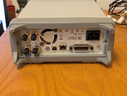
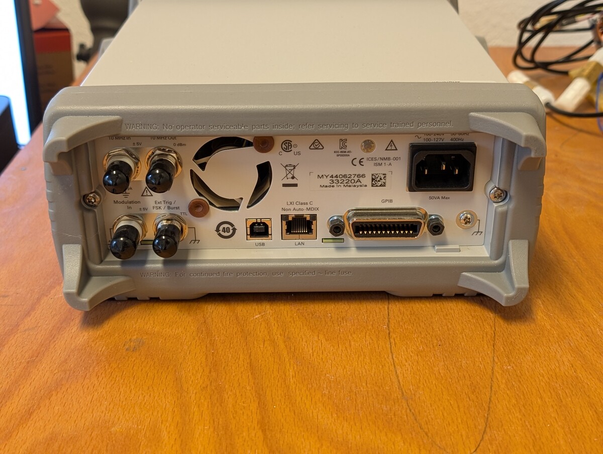
to service trained personnel. 10 MHz IN, 10 MHz OUT, ±5V, 0 dBm, C US, ICES/NMB-001, ISM 1-A, 100-127V 400Hz, MY44062766, 33220A, Made in Malaysia, Modulation In, ±5V, Ext Trig / FSK / Burst TTL, 40, GPIB, 50VA Max, USB, LAN, WARNING: For continued fire protection, use specified line fuse.
The thermistor is used to Table 2. NTC THRMISTOR SPECIFICATION Parameter Symbol Condition Min. Typ. Max. Unit Resistance R 25 TC= 25°C 99 100 101 kW Resistance R100 TC= 100°C 5.18 5.41 5.60 kW Temperature Range −40 +125 °C ] [ e l V e n t s e r t i r h T Case Temperature [5C] Figure 8. NTC Thermistor
displayed. displayed. Day (0D to 9999D) T2-1 T1-4 T1-7 MAIN VOL:----- T1-2. POWER-RELAY ON OUTLVL MAX: 00 RST NUM: 00003 Maximum value / The operation frequency of the power relay (RY541) Minimum value / 0 to FF −80.0 to +16.0 dB is displayed. T1-8. PROTECTION LOCK T1-5. POWER OFFTIME-OUT The operation
Complete Unit" Strings.123=<Current> Strings.124=Yes|No Strings.125=Yes|No Strings.126=Yes|No Strings.127=Documentation Exists Strings.128=Documentation already exists. Do you still want to go to the record? Strings.129=Unlock version for changes Strings.130=Do you really want to change the versioned documentation
value 0.0.0.0 is forbidden. If no gateway is to be defined then this value is to be set to either 127.0.0.1 or the Local IP address. Remark : The MODBUS messaging service doesn't require the fragmentation function in the IP layer. The local IP End Point shall be configured with a local IP Address and
den Schalldruck. Fertig gibt es sowas in der Richtung von IMG Stageline MPA-102, allerdings nur mit max. 24 Volt Phantomspeisung. Liebe Grüße Pfungstadt
▯ } I ( ▯ 2 › 2 LED Driver IC ▯ D O ▯ î C ▯ +12V_FAN LED Forward Voltage E 2 2 1 1 SDICS ▯ +15V R_Max 2.4V x 4 pcs = 9.6V L L L L SDI_CLKL ) For EMI ▯ 3 3 3 2 2 2 1 1 1 G_Max 3.3V x 4 pcs = 13.2V C227 C100p50N0402 LED1_G L L L L L L L L L Pin Definerd 6 5 4 3 2 1 O ▯ C567 C100p50N04N2 LED1_R B_Max 3.3V
MCU 3. Technical parameters Type JDY-41 Color Green Working frequency band 2.4G Transmitting power Max 12db Working temperature -40℃ - 80℃ Receiving sensitivity -96db Transmission distance 160m Working voltage 2.2V-3.6V TX current 40mA RX current 24mA Sleep current 10uA Communication interface Standard
Erde isolierten > Schaltkreis, Die berühmte, schon in der DDR erfundene Monode? Kennwerte: I_max_linksvorbei und I_max_rechtsvorbei... > der eine bestimmte Spannung ausgibt, sagen wir > 5 V DC + 0.5 V AC. Geht nicht. Eine Spannung liegt zwischen *ZWEI* Punkten an. Mit der Forderung
Bezugspotenzial dieser Schaltung (=Masse). Das ist genauso sinnvoll wie zu sagen: "Hier sind 127 Meter!", wenn ich keine Angabe darüber mache, wo der Bezugspunkt für die Längenmessung ist. Der Minus-Pol der Batterie in meinem Funkwecker mag -3.194GV gegen den linken Vorderreifen des Lunochod
) Alarm: Once alarm/Everyday alarm:One system each FM S/N ratio: Monaura:l 70dB Sleep: Sleep timer:Max. 90 minutes Stereo:70dB n nGeneral FM THD+N (1kHz) :Monaura: l 0.4% Stereo:0.4% Power supply: (for E2): AC 230 V, 50 Hz / 60Hz (for E1C): AC 220V, 50Hz (for JP): AC 100V, 50/60Hz Power consumption:
Schriftstile benötigt. Außerdem sind für die Schriftgröße 8*8 Pixel nicht nur die Ascii-Zeichen bis 127 (keine deutschen Umlaute) enthalten. Bei Bedarf kann hier der Ascii-Zeichensatz für die Codepage 850 Erweiterung eingeschaltet werden. Die Einstellungen im Header sind: /* --------------------------
MAGNETOM Free.Max Breaking barriers siemens-healthineers.com/free-max Introduction Barriers limit the reach of MRI Today more than ever, access to healthcare should be a matter of course. But barriers still exist that
230V AC or 115V AC ± 10%, 50/60Hz Installation Category II Power Consumption: Single output: 250VA max; Triple output: 500VA max. Operating Range: +5ºC to +40ºC, 20% to 80% RH Storage Range: −40ºC to + 70ºC Environmental: Indoor use at altitudes up to 2000m, Pollution Degree 2. Cooling: Intelligent variable-speed

 Bild
Bild
 Bild
Bild
 Bild
Bild
 Bild
Bild