-
PDF
mt6_06.pdf
Ground 2 MC_D03 Databus 3 MC_D04 Databus 4 MC_D05 Databus 5 MC_D06 Databus 6 MC_D07 Databus 7 MC_CE1 Card Enable signal 8 MC_A10 Memory address bus 9 MC_OE Output Enable signal 10 MC_A09 Memory address bus 11 MC_A08
in „CAN-Bus Ansteuerung über C# - Compact Framework“ · Softwareentwicklung ·
-
PDF
drm001.pdf
On The program c:\pemicro\ics08gpz\prog08sz.exe can now be retried. 4.9.3 Programming Circuit The MC68HC908GP32 programmer is configured in a modified form to that recommended in the MC68HC908GP32 Technical Data, Motorola document order number MC68HC908GP32/H REV. 4. It uses two sections of a three-state
in „AVR ATTiny84A mit C++ Werte an bestimmte Speicherstelle schreiben“ · Mikrocontroller und Digitale Elektronik ·
-
Datei
hal_dma.h
// DMA_TRIGSRC_SERCOM5_RX, // DMA_TRIGSRC_SERCOM5_TX, // DMA_TRIGSRC_TCC0_OVF, // DMA_TRIGSRC_TCC0_MC0, // DMA_TRIGSRC_TCC0_MC1, // DMA_TRIGSRC_TCC0_MC2, // DMA_TRIGSRC_TCC0_MC3, // DMA_TRIGSRC_TCC1_OVF, // DMA_TRIGSRC_TCC1_MC0, // DMA_TRIGSRC_TCC1_MC1, // DMA_TRIGSRC_TCC2_OVF, // DMA_TRIGSRC_TCC2_MC0, // DMA_TRIGSRC_TCC2_MC1, // DMA_TRIGSRC_TC3_OVF, // DMA_TRIGSRC_TC3_MC0, // DMA_TRIGSRC_TC3_MC1, // DMA_TRIGSRC_TC4_OVF, // DMA_TRIGSRC_TC4_MC0, // DMA_TRIGSRC_TC4_MC1, // DMA_TRIGSRC_TC5_OVF, // DMA_TRIGSRC_TC5_MC0, // DMA_TRIGSRC_TC5
in „SAMD21: Selbst geschriebene HAL-Module, Anregungen, Kritik.“ · Mikrocontroller und Digitale Elektronik ·
-
PDF
mb1045_changed.pdf
TX MC_VL MC_VL EXP_IO0 uSD_CLK uSD_CLK MC_UH MC_UH B EXP_IO1 uSD_CMD uSD_CMD MC_UL MC_UL B EXP_IO2 uSD_D0 uSD_D0 MC_CurrentA MC_CurrentA EXP_IO3 uSD_D1 uSD_D1 MC_CurrentB MC_CurrentB EXP_IO4 uSD_D2 uSD_D2 MC_CurrentC MC_CurrentC EXP_IO5 uSD_D3 uSD_D3 MC_EnA MC_EnA EXP_IO6 MC_EnB MC_EnB EXP_IO7 MC_NTC MC_NTC EXP_IO8 MC_DissipativeBrake MC_DissipativeBrake EXP_IO9 MC_EmergencySTOP MC_EmergencySTOP EXP_IO10
-
PDF
mb1045_changed_korrigiert.pdf
TX MC_VL MC_VL EXP_IO0 uSD_CLK uSD_CLK MC_UH MC_UH B EXP_IO1 uSD_CMD uSD_CMD MC_UL MC_UL B EXP_IO2 uSD_D0 uSD_D0 MC_CurrentA MC_CurrentA EXP_IO3 uSD_D1 uSD_D1 MC_CurrentB MC_CurrentB EXP_IO4 uSD_D2 uSD_D2 MC_CurrentC MC_CurrentC EXP_IO5 uSD_D3 uSD_D3 MC_EnA MC_EnA EXP_IO6 MC_EnB MC_EnB EXP_IO7 MC_NTC MC_NTC EXP_IO8 MC_DissipativeBrake MC_DissipativeBrake EXP_IO9 MC_EmergencySTOP MC_EmergencySTOP EXP_IO10
-
Datei
avrasm.txt
insgesamt 16 Bit, auch "word" genannt). Jetzt schauen wir uns doch mal an, wie die Assembler-Programme vom MC abgearbeitet werden. Dazu muß das assemblierte Programm in den Programmspeicher des MC geladen werden. Wenn der MC dann gestartet wird bzw. zurückgesetzt wird (reset), dann liest er automatisch den Befehl
-
PDF
mc39i_hd_v0102.pdf
that packet switched calls may go on without terminating the selected CYCLIC SLEEP mode. This allows MC39i to become active, for example to perform a GPRS data transfer, and to resume power saving after the GPRS data transfer is completed. MC39i_HD_V01.02 Page 32 of 76 12.11.2003 MC39i Hardware Interface
-
PDF
TMS320F2812_Datasheet.pdf
r 0x3F F000 XINTF Zone 7 (16K × 16, XZCS6AND7) 4 P ÍÍÍÍÍÍÍÍÍÍÍ Boot ROM (4K × 16) ( (Enabled if MP/MC = 1) (Enabled if MP/MC = 0) 0x3F FFC0 BROM Vector - ROM (32 × 32) XINTF Vector - RAM (32 × 32) (Enabled if VMAP = 1, MP/MC = 0, ENPIE = 0) (Enabled if VMAP = 1, MP/MC = 1, ENPIE = 0) LEGEND: Only one
in „Wieder eine Elektronik-Anfängerfrage“ · Mikrocontroller und Digitale Elektronik ·
-
PDF
Timing_S12.pdf
10 11 12 12 R/W LSTRB Figure A-15. Example 2a: Emulation Single-Chip Mode — Read Followed by Write MC9S12XE-Family Reference Manual , Rev. 1.15 1334 Freescale Semiconductor Appendix A Electrical Characteristics Table A-32. Example 2a: Emulation Single-Chip Mode Timing 50 Mhz bus, V DD5=5.0V (EWAIT disabled
in „extem schneller demultiplexer gesucht“ · Mikrocontroller und Digitale Elektronik ·
-
 Bild
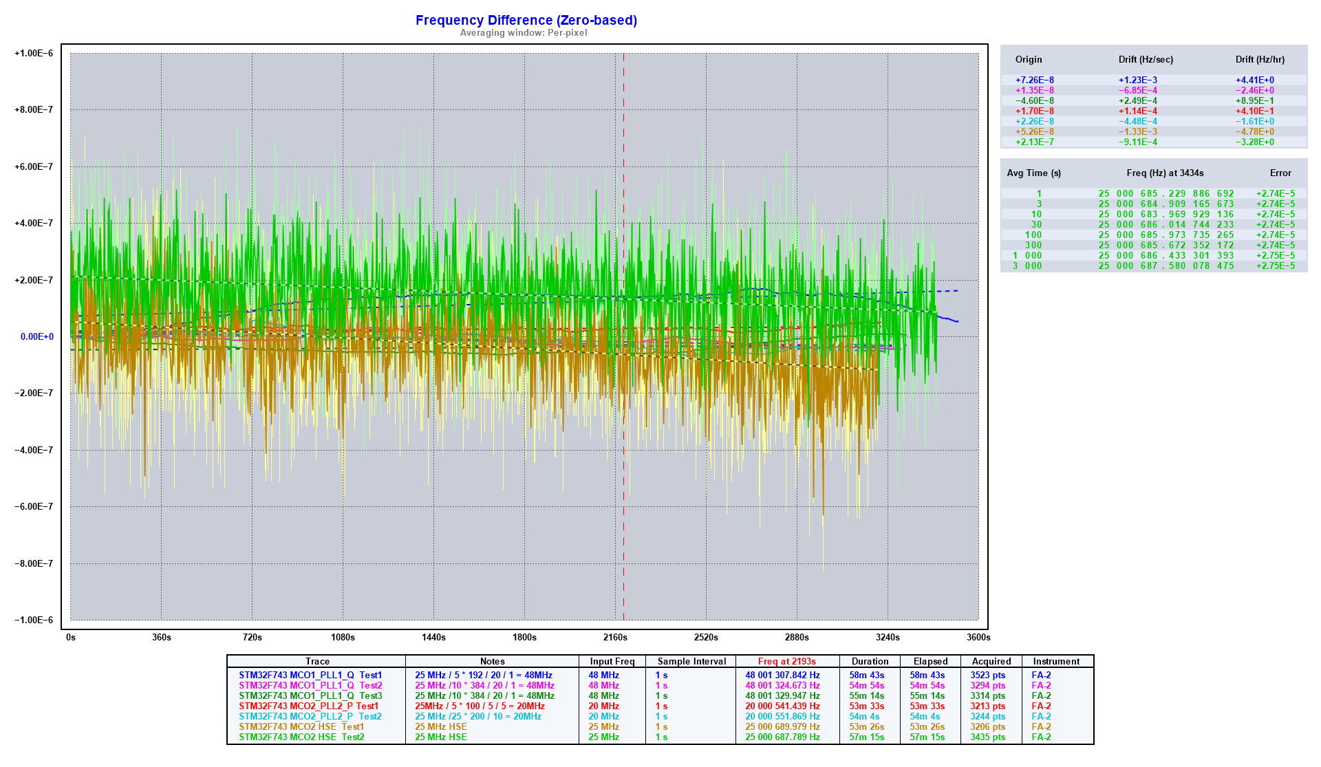
Diagramm der Frequenzabweichung
3240s 360s Trace Input Freq Sample Interval Freq at 2151s Duration Elapsed Acquired Instrument STM32F434 MC01_PLL_Q Test1 25 MHz / 5192 / 20 / 1 = 48MHz 1 s 48 001 307.842 Hz 58m 43s 3523 pts FA-2 STM32F434 MC01_PLL_Q Test2 25 MHz / 5192 / 20 / 1 = 48MHz 1 s 48 001 329.947 Hz 55m 14s 3314 pts FA-2 STM32F434 MC01_PLL_Q Test3 25 MHz / 5192 / 20 / 1 = 48MHz 1 s 48 001 325.947 Hz 20m 33s 1255 pts FA-2 STM32F434 MC02_PLL_P Test1 25 MHz / 200 / 10 / 5 = 20MHz 1 s 25 000 511.809 Hz 54m 4s 3244 pts FA-2 STM32F434
in „STM32H743 PLL“ · Mikrocontroller und Digitale Elektronik · · Screenshots
-
PDF
MC145012.pdf
Document Number: MC145012 Freescale Semiconductor Technical Data Rev 9.0, 11/2006 Photoelectric Smoke Detector IC with MC145012 I/O and Temporal Pattern Horn Driver The CMOS MC145012 is an advanced smoke detector component
in „Lithiumbatterien in Rauchmeldern - gefährlich?“ · Haus & Smart Home ·
-
Datei
system.ucf
"; TIMESPEC "TS_MC_PHY_INIT_DATA_SEL_0" = FROM "TNM_PHY_INIT_DATA_SEL" TO "TNM_CLK0" "TS_MC_CLK" * 4; TIMESPEC "TS_MC_PHY_INIT_DATA_SEL_90" = FROM "TNM_PHY_INIT_DATA_SEL" TO "TNM_CLK90" "TS_MC_CLK" * 4; ## Select (address) bits for SRL32 shift registers used in stage3/stage4 ## calibration INST "*/u_phy_calib/gen_gate_dly*.u_ff_gate_dly" TNM = "TNM_GATE_DLY"; TIMESPEC "TS_MC_GATE_DLY" = FROM "TNM_GATE_DLY" TO "TNM_CLK0" "TS_MC_CLK" *
in „Xilinx ML07 PowerPC GPIO Interrupt“ · FPGA, VHDL & Co. ·
-
PDF
AVR200_Multiply_and_Divide_Routines.pdf
same for both versions: 3. Call “mpy16u” 1. Load register variables “mp16uL”/”mp16uH” with 4. The 32-bit result is found in the four-byte register multiplier Low and High byte, respectively. variable “m16u3:m16u2:m16u1:m16u0”. 2. Load register variables “mc16uH”/”mc16uH” with Observe that to minimize
in „Division großer Integerzahlen“ · Mikrocontroller und Digitale Elektronik ·
-
PDF
AVR200_Multiply_and_Divide_Routines.pdf
same for both versions: 3. Call “mpy16u” 1. Load register variables “mp16uL”/”mp16uH” with 4. The 32-bit result is found in the four-byte register multiplier Low and High byte, respectively. variable “m16u3:m16u2:m16u1:m16u0”. 2. Load register variables “mc16uH”/”mc16uH” with Observe that to minimize
in „Division 16bit / 8bit Zahl 8051 Assembler“ · Mikrocontroller und Digitale Elektronik ·
-
PDF
AVR200_Multiply_and_Divide_Routines.pdf
same for both versions: 3. Call “mpy16u” 1. Load register variables “mp16uL”/”mp16uH” with 4. The 32-bit result is found in the four-byte register multiplier Low and High byte, respectively. variable “m16u3:m16u2:m16u1:m16u0”. 2. Load register variables “mc16uH”/”mc16uH” with Observe that to minimize
in „Division mit Rest“ · Mikrocontroller und Digitale Elektronik ·
-
PDF
Multi-Divi.pdf
same for both versions: 3. Call “mpy16u” 1. Load register variables “mp16uL”/”mp16uH” with 4. The 32-bit result is found in the four-byte register multiplier Low and High byte, respectively. variable “m16u3:m16u2:m16u1:m16u0”. 2. Load register variables “mc16uH”/”mc16uH” with Observe that to minimize
in „AVR Reziprok-Wert (Umkehr-Wert) berechnen“ · Mikrocontroller und Digitale Elektronik ·
-
PDF
sed1353.pdf
but also for small hand held equipments, too. FUNCTIONS Display memory interface 16-bit, 16 MHz and MC68xxx MPU interface. 128KB (one 64K × 16 SRAM) READY or WAIT# terminal controlled 8/16 bits 128KB (two 64K × 8 SRAM) MPU interface. 64KB (two 32KB × 8 SRAM) Either index register approah or direct mapping
in „SED1353 an AVR“ · Mikrocontroller und Digitale Elektronik ·
-
PDF
Elektronikladen07.pdf
Entwicklung zu bieten, haben wir das HC08 Welcome Kit entwickelt. Zum Einsatz kommt darauf eine MCU vom Typ MC68HC908GP32, ein echtes Universaltalent mit einer Vielzahl integrierter Peripherie- module. Auch Programmspeicher gibt es reichlich (32KB!), da kann der beliebte (aber in die Jahre gekommene) HC11 nicht
in „MC68000 von Motorolla“ · Mikrocontroller und Digitale Elektronik ·
-
PDF
mc35i_hd_v0103.pdf
*Normal mode covers TALK, IDLE and SLEEP modes MC35i_HD_V01.03 Page 32 of 77 07.05.2004 MC35i Hardware Interface Description s Confidential / Released m obile 3.4 Power saving SLEEP mode reduces the functionality of the MC35i module to a minimum and
in „Taste im Hörer an GSM-Modul“ · Mikrocontroller und Digitale Elektronik ·
-
Datei
mc9s08ac32.h
/* Based on CPU DB MC9S08AC60_64, version 3.00.040 (RegistersPrg V2.32) */ /* ** ################################################################### ** Filename : mc9s08ac32.h ** Processor : MC9S08AC32CPU ** FileFormat: V2.32
in „Probleme mit CodeWarrior“ · Mikrocontroller und Digitale Elektronik ·
-
PDF
mc3362.pdf
Order this document by MC3362/D MC3362 Low-Power Narrowband FM Receiver . . . includes dual FM conversion with oscillators, mixers, quadrature discriminator, and meter drive/carrier detect circuitry. The MC3362 also has LOW–POWER
-
PDF
H616_JC_6Z_V1_2_MCU.pdf
VSS_2 GND 6 VBAT NC 73 7 PC13-TAMPERCRTC(5) JTMS-SWDIO//PA13 72 SWDIO 8 PC14-OSC32_IN(5) PA12/USART1_RTS/USBDP/CAN_TX(8)/TIM1_ETR 71 MC_USB_P 9 PC15-OSC32_OUT(5) PA11/USART1_CTS/USBDM/CAN_RX(8)/TIM1_CH4 70 MC_USB_N GND 3V3 10 69 LCD_EN 11 VSS_5 PA10/USART1_RX(8)/TIM1_CH3(8) 68 VDD_
in „Induktiver Näherungsschalter tauschen Probleme“ · Analoge Elektronik und Schaltungstechnik ·
-
Datei
Liste.txt
cdp1833ce Upverter ?? 10x cf72300x n 8740 SMD ???? 36x STE 081164 10X 4050 HEX-Non Inverting Buffer 10x MC14093B Quad 2-Input NAND Schmitt Trigger 10x MC14516BCP Binary Up/Down Counter 6x MC14510B BCD UP/DOWN Counter 6x MC14543b BCD-to-Seven Segment Latch/Decoder/Driver for Liquid Crystals 23x 4042Be CMOS
-
PDF
rf__0_4_schem.pdf
PIP1025 B P_DAH MCU 3V Supply PIP1026 GND GND GND J2J2 P_DIT VCC_3V Soft controlled 5V Supply PIJ20T 32 VCC_5V Soft controlled 8V Supply PIJ20S I0 C333 VCC_8V GND PIP1030 U4U MC7805BTG Paddles C32311nF 30 VCC_8V PIU40Vin VoutPIU403 VCC_5V I1 1nF Header 30 GND UI Board Interface I1 CO28 P2P2 BNC 13-60-2
-
PDF
Typen.pdf
30 SN7426N 200 74HC27 50 MC14044BCP 22 SN74LS27N 30 SN7454N 200 SN74S20N 70 MC14582B 30 SN74S30N 50 SN74S32N 60 SN74LS136N 100 SN7430N 90 SN7432N 200 SN74LS273N 90 SN74LS30N 50 SN74LS241N 100 SN7430N 70 74HCT138E 14 74F37N 60 74LS32N
in „Riesensammlung IC Prozessoren Halbleiter - Was tun?“ · Markt ·
-
PDF
Typen_sort.pdf
75 MC14012BCP 90 MC14015BCP 90 MC14021CP 25 MC14023BCP 90 MC14024 1 MC14025BCP 170 MC14027BCP 17 MC14028BCP 60 MC14029 18 MC14035BCP 25 MC14040BCP 45 MC14043BCP 26 MC14044BCP 22 MC14051BCP 70 MC14052BCP 20 MC14053BCP 25 MC14066BCP 40 MC14068BCP 40 MC14069BCP 30 MC14072BCP 90 MC14076BCP 80 MC14077 65 MC14078BAL 25 MC14081 30 MC14082BCP 80 MC14093BCP 75 MC14419P 100 MC14490VP 30 MC14495P 40 MC14501CP 80 MC14502BCP
in „Riesensammlung IC Prozessoren Halbleiter - Was tun?“ · Markt ·
-
PDF
2012_02-RIAA.pdf
/b 86dBA gaincommutéJP1/JP2(dB) G D (source 750 Ω) 0 0 0 S/b(entrée court-ci)cuit88dBA 5 5,22 5,23 MC: 0.2 mV entrée, DHT+b 0,016% 1 kHz, JP1/2 =15 dB S/b 76dB 10 10,95 10,97 (source 1 Ω) S/b 79,5dBA 15 14,71 14,72 gain d'étage MC 29,8dB 20 19,52 19,51 elektor 05-2012 67 Audio & hAute-fidÉlitÉ 4x2SA1085
in „Empfehlung für Phono-Vorverstärker-Schaltplan?“ · Analoge Elektronik und Schaltungstechnik ·
-
Datei
main.c
(void); /* Private variables ---------------------------------------------------------*/ CMCI oMCI[MC_NUM]; CMCT oMCT[MC_NUM]; uint32_t wConfig[MC_NUM] = {UI_CONFIG_M1,UI_CONFIG_M2}; /* Private macro -------------------------------------------------------------*/ /* Private variables ----------------
in „STM32F4 - CAN1 empfängt nichts“ · Mikrocontroller und Digitale Elektronik ·
-
PDF
MC39I_AT_COMMANDS.pdf
Hex character hex. value ASCII character Esc sequence Esc sequence Ö 5C \ \5C 5C 35 43 " 22 \22 5C 32 32 ò 08 BSP \08 5C 30 38 @ 00 NULL \00 5C 30 30 MC39i_ATC_V01.02 Page 13 of 314 11.11.2003 MC39i AT Command Set s Confidential / Released m obile CAUTION: Often, the editors of terminal programs do not
in „DTMF mit GSM Modem auswerten“ · Mikrocontroller und Digitale Elektronik ·
-
Datei
AmpMod.c
Input)); // wurzel(Input); processing(); Out = (Uint32) Output; McbspOut = ( Out<<16 );//|( Out & 0x0000ffff ); //McbspOut = (Out<<16); MCBSP_write(hMcbsp1,McbspOut); return; } /* enableMcBSP1 *----------------------------------------------------------------------------------*/ void EnableMcBSP1(void) { hMcbsp1 = MCBSP_open(MCBSP_DEV1,MCBSP_OPEN_RESET); /* setup serial port */ MCBSP_configArgs(hMcbsp1, 0x00000000, /* reset serial port */ 0x000000A0, /* set rx control reg to 32 bit data/frame
in „TI 6711 DSK AM-Demodulation“ · Digitale Signalverarbeitung / DSP / Machine Learning ·
-
Datei
goertzel.asm
multiplies signed the two 16-bit register variables ;* mp16sH:mp16sL and mc16sH:mc16sL. ;* The result is placed in m16s3:m16s2:m16s1:m16s0. ;* The routine is an implementation of Booth's algorithm. If all 32 bits ;* in the result are needed, avoid calling the routine with ;*
in „CTCSS decoder / encoder“ · Mikrocontroller und Digitale Elektronik ·
-
PDF
kicad_8450_dcm_liste_neu_v3.pdf
shutdown, with receiver/driver enable, 32 receiver drive kapacitity, 0 to +70 degree Celcius, DIP-14 and SOIC-14 MC1413 High Voltage, High Current Darlington Transistor Arrays MC1413P High Voltage, High Current Darlington Transistor Arrays MCP2551
in „KiCAD Eeschema, Bibliotheksdokumentation *.dcm als PDF-Datei“ · Platinen ·
-
PDF
MC9S08MM128RM.pdf
the property of their respective owners.© Freescale Semiconductor, Inc. 2012. All rights reserved. MC9S08MM128 RMAD Rev. 1 05/2012 MC9S08MM128 MC9S08MM64 MC9S08MM32 MC9S08MM32A Reference Manual HCS08 Microcontrollers MC9S08MM128RM Rev. 3 07/2010 freescale.com MC9S08MM128 series 8-Bit HCS08 Central Processor
in „Freescale s08mm128 und USB“ · Mikrocontroller und Digitale Elektronik ·
-
Datei
hal_dma.h
// DMA_TRIGSRC_SERCOM5_RX, // DMA_TRIGSRC_SERCOM5_TX, // DMA_TRIGSRC_TCC0_OVF, // DMA_TRIGSRC_TCC0_MC0, // DMA_TRIGSRC_TCC0_MC1, // DMA_TRIGSRC_TCC0_MC2, // DMA_TRIGSRC_TCC0_MC3, // DMA_TRIGSRC_TCC1_OVF, // DMA_TRIGSRC_TCC1_MC0, // DMA_TRIGSRC_TCC1_MC1, // DMA_TRIGSRC_TCC2_OVF, // DMA_TRIGSRC_TCC2_MC0, // DMA_TRIGSRC_TCC2_MC1, // DMA_TRIGSRC_TC3_OVF, // DMA_TRIGSRC_TC3_MC0, // DMA_TRIGSRC_TC3_MC1, // DMA_TRIGSRC_TC4_OVF, // DMA_TRIGSRC_TC4_MC0, // DMA_TRIGSRC_TC4_MC1, // DMA_TRIGSRC_TC5_OVF, // DMA_TRIGSRC_TC5_MC0, // DMA_TRIGSRC_TC5
in „Bare-Metal ATSAM“ · Mikrocontroller und Digitale Elektronik ·
-
Datei
kessel_init.htm
92 MC... </FONT></P> <P><FONT face="MS Shell Dlg" color="#000000"><B>Answer: 28.11.2013 19:57:11.92864 (+0.2003 seconds) </B></FONT></P> <P><FONT face="Courier New" color="#0000ff"> 4D 43 08 00 32 68 01 00
in „Fröling Heizungssteuerung auslesen.“ · Mikrocontroller und Digitale Elektronik ·
-
PDF
schematic.PDF
5V DUT1 input -12dBm .. 4dBm Offset oscillator input 12 0 2 82 X5X D5D R818 R822 X6X D6D R8383 R848 32K101-400L5C737 MC100EL16DG 82R 82R 32K101-400L5C747 MC100EL16DG 82R 82R 100n 10 1 100n 1 81 PIX501 PIC7302 PIC730PIDD02 QPID507 PODUT1_P PIX601 PIC7402 PIC740PIDD02 QPID607 PLO1_PP PIX50 COR5 PIDD03 QPID506
-
PDF
dsk6713_TechRef__1_.pdf
28 N/C - No connect 29 FSR0 I/O McBSP0 receive frame sync 30 DR0 I McBSP0 receive data 31 GND Vss System ground 32 GND Vss System ground 33 CLKX1 I/O McBSP1 transmit clock 34 CLKS1 I McBSP1 clock source 35 FSX1 I/O McBSP1 transmit frame sync 36 DX1 O McBSP1 transmit data 37 GND Vss System ground 38 GND Vss System ground 39 CLKR1 I/O McBSP1 receive clock 40 N/C - No connect 41 FSR1 I/O McBSP1 receive frame sync 42 DR1 I McBSP1 receive data 43 GND Vss
in „Kamera für TMS320C6713“ · Digitale Signalverarbeitung / DSP / Machine Learning ·
-
PDF
dsk6713_TechRef.pdf
28 N/C - No connect 29 FSR0 I/O McBSP0 receive frame sync 30 DR0 I McBSP0 receive data 31 GND Vss System ground 32 GND Vss System ground 33 CLKX1 I/O McBSP1 transmit clock 34 CLKS1 I McBSP1 clock source 35 FSX1 I/O McBSP1 transmit frame sync 36 DX1 O McBSP1 transmit data 37 GND Vss System ground 38 GND Vss System ground 39 CLKR1 I/O McBSP1 receive clock 40 N/C - No connect 41 FSR1 I/O McBSP1 receive frame sync 42 DR1 I McBSP1 receive data 43 GND Vss
in „TMS320C6713 Schnittstelle“ · Digitale Signalverarbeitung / DSP / Machine Learning ·
-
PDF
ATMEL-Motor_Entwicklungsboard.pdf
*******************************************************************/ #include "config.h" #include "mc_lib.h" #include "mc_control.h" #include "mc_drv.h" #include "serial.h" #include "adc\adc_drv.h" #include <stdio.h> #include "mc_test_procedure.h" U16 g_regulation_period = 0; //!< Define the sampling
in „Stromregeler Testboard ATAVRMC100“ · Mikrocontroller und Digitale Elektronik ·
-
PDF
qsc_gx5_sh_ts_sch.pdf
R144 C61 35V 1/8W D37 P-REF 2 1 3 R43 R48 U10 1/10W 2.49K Q23 D14 R100 61.5v U13 1 PCNT 2.49K Q49 D32 R162 R116 T 2 U1 22PF 5.90K 0v 1 8 1 PCNT MMST3906 2 24.9K MUR1520 62v W1A W2A 1 8 1/10W 1 PCNT MMST3906 2 24.9K 4 3 MC33078 0.5 Vrms 5200VT 1 PCNT 10PF 69.8K P2 GND V+ 1/10W 10UF IMBD4148 1 PCNT C50
in „QSC GX5 negative Spannung am Ausgang“ · Mikrocontroller und Digitale Elektronik ·
-
PDF
qsc_gx5_sh_ts_sch.pdf
R144 C61 35V 1/8W D37 P-REF 2 1 3 R43 R48 U10 1/10W 2.49K Q23 D14 R100 61.5v U13 1 PCNT 2.49K Q49 D32 R162 R116 T 2 U1 22PF 5.90K 0v 1 8 1 PCNT MMST3906 2 24.9K MUR1520 62v W1A W2A 1 8 1/10W 1 PCNT MMST3906 2 24.9K 4 3 MC33078 0.5 Vrms 5200VT 1 PCNT 10PF 69.8K P2 GND V+ 1/10W 10UF IMBD4148 1 PCNT C50
in „QSC GX5 negative Spannung am Ausgang“ · Mikrocontroller und Digitale Elektronik ·
-
Datei
UIExportedFunctions.h
EF_UI_GetRevupData, EF_UI_DACChannelConfig, EF_UI_SetCurrentReferences, EF_UI_NUMBERS }; typedef int32_t (*pUI_GetReg_t) (CUI,MC_Protocol_REG_t); typedef bool (*pUI_ExecSpeedRamp_t)(CUI,int32_t,uint16_t); typedef bool (*pUI_SetReg_t)(CUI,MC_Protocol_REG_t,int32_t); typedef bool (*pUI_ExecCmd_t)(CUI,uint8_t); typedef uint32_t (*pUI_GetSelectedMCConfig_t)(CUI); typedef bool (*pUI_SetRevupData_t)(CUI,uint8_t,uint16_t,int16_t,int16_t); typedef bool (*pUI_GetRevupData_t)(CUI,uint8_t,uint16_t*,int16_t*,int16_t*); typedef void
in „STM32 PMSM FOC set Speed in rpm“ · Mikrocontroller und Digitale Elektronik ·
-
PDF
at91sam.pdf
analysis by an operating system, the Memory Controller integrates an Abort Status register set. The full 32-bit wide abort address is saved in MC_AASR. Parameters of the access are saved in MC_ASR and include: the size of the request (field ABTSZ) the type of the access, whether it is a data read or write,
in „SPI-Initialisierung von zwei Geräte über den gleichen Bus“ · Mikrocontroller und Digitale Elektronik ·
-
PDF
doc4779atr2406.pdf
Application Notes. 7. PLL Principle Figure 7-1. PLL Principle Programable counter PC "- Main counter MC "- Swallow counter SC f = 1728 kHz × (S × 32 + S ) VCO MC SC External loop filter PA driver Phase frequency Charge Divider detector PD pump VCO by 2 PD= 1728 kHz Mixer Gaussian filter GF Reference counter
in „Gauss Anpassung Register“ · Mikrocontroller und Digitale Elektronik ·
-
PDF
MC7800-D.pdf
MC7800, MC7800A, MC7800AE, NCV7800 1.0 A Positive Voltage Regulators These voltage regulators are monolithic integrated circuits designed as fixed-voltage regulators for a wide variety of applications http
-
Datei
AFMotorcpp.txt
break; default: return; } switch (cmd) { case FORWARD: latch_state |= _BV(a); latch_state &= ~_BV(b); MC.latch_tx(); break; case BACKWARD: latch_state &= ~_BV(a); latch_state |= _BV(b); MC.latch_tx(); break; case RELEASE: latch_state &= ~_BV(a); latch_state &= ~_BV(b); MC.latch_tx(); break; } } void AF_DCMotor
in „Arduino 2560 PWM Frequenz ändern auf 100Hz“ · Mikrocontroller und Digitale Elektronik ·
-
Datei
avr200b.asm
,mc16uL/m16u0,mc16uH/m16u1,m16u2, ;* m16u3) ;* ;*************************************************************************** ;***** Subroutine Register Variables .def mc16uL =r16 ;multiplicand low byte .def
in „Suche Routine zum Dividieren zweier 16 Bit Zahlen“ · Mikrocontroller und Digitale Elektronik ·
-
Datei
PCM1738.asm
PB2 MUSS Output sein, da sonst SPI auf die Klappe fällt. OUT DDRB, tmp LDI tmp, 0xFB ; Defaults ; MC(PB2) L OUT PortB, tmp ; Timer0init (IRQ) ldi tmp, 10 out OCR0A, tmp ldi tmp, 0x02 ; WGM00/01 - CTC out TCCR0A, tmp ldi tmp, 0x03 ; Teiler 32 ; WGM02 - CTC out TCCR0B, tmp ldi tmp, 0x02 ; Irq an sts TIMSK0
in „DAC PCM1738 mode control programmieren“ · Mikrocontroller und Digitale Elektronik ·
-
PDF
IR.pdf
fast) inc impulses nop out PORTB,one out TCNT0,zero;reset timer reti ONE1: ;program creates a "1" (32 pulses low follow by 32 high). The symetric character of the rc5 code allowes to count ;pulses. the low pulses are created by the use of the data direction register as imputs . The pin cange has no effect
in „Pinchange-Interrupt“ · Mikrocontroller und Digitale Elektronik ·
-
Datei
i2c.c
0x100); return ( I2CMasterState ); } #define MC24LC64_ADDR 0xa0 // I2C address of the 24LC64 EEPROM int i2c_wr_eeprom(uint32_t Addr, const void *pIn, uint32_t len) { uint32_t l; if (!pIn || len>0x0ffff) return -1; while (len>0) { if ( I2CInit( (uint32_t)I2CMASTER ) == 0 ) // initialize I2c return 1; // Fatal error l=(len>32) ? 32 : len; memcpy((void*)I2CMasterBuffer+3, pIn, l); I2CWriteLength = l+3 ; I2CReadLength = 0; I2CMasterBuffer[0] = MC24LC64_ADDR; I2CMasterBuffer[1] = (Addr & 0xff00)>>8; // address MSB I2CMasterBuffer
in „CAN UP - Aktor (LPC11Cxx)“ · Mikrocontroller und Digitale Elektronik ·