............................................................ 6 3.4 Components for operation on 303.85 MHz................................................................................ 7 4. Front end measurement results.................................................................................
DC betitelt) und beidseitig abgeglichen. Der Längswiderstand war etwas zu klein, daher nur ca. 39.85 dB Dämpfung, das ließe sich nich verbessern. Aber mehr muss ich jetzt wirklich nicht rumspielen um zu zeigen, dass auch mit Bauteilen aus dem vergangenen Jahrtausend (AKA in makroskopischer Ausführung
Sowas schaut intern dann deinem gedrängten Aufbau schon ähnlich, siehe http://sprut.de/electronic/rf/bas_attenuator.html
/stores/servlet/Search?catalogId=15001&langId=-3&storeId=10161&categoryId=700000004344&sort=P_ATT_BASE_VALUE_1012845_DE_DE&eq=N%3D203961%2B312893079%2B2008%26amp%3BNs%3DP_PRICE_FARNELL_DE%257c0%26amp%3BNtpc%3D1%26amp%3BNtpr%3D1&showResults=true&aa=true&pf=312893079&vw= Im obigen Link habe ich die
StepUp, aber für ein Projekt wie z.B. das hier https://www.youtube.com/channel/UCe8xO6ANyH9VR9KUkA85Spg ist es zu Beginn einfach hilfreich es auf 5V auszulegen, mit allen Nachteilen.
Antriebsstrang Arbeitszeit: 40h Ü.-Stunden: Auszahlung oder abfeiern Urlaub: 30 Tage Gehalt: ca. 85k€ Entwicklung: 2019: 68k€ bei 40h/Woche 2020: 75k€ bei 36h/Woche 2021: ~85k bei 40h/Woche Ausblick 2022: ~91k€ bei 40h/Woche Zusatzleist.: BAV ________________________________
40h Ü.-Stunden : 10h pro Monat mit dem Gehalt abgegolten Urlaub : 30 Tage Gehalt : base: 80k , bonus: 10k, rsu/y: 20k Zusatzleist. : übliche Konzern Benefits
Im Apple II+ kam dann noch eine Z80 hinzu. Damit konnte man dann CP/M fahren, um z.B. WordStar, dBase, Turbo Pascal 1.0 etc. zu benutzen.
Apple II+ kam dann noch eine > > Z80 hinzu. Damit konnte man dann CP/M fahren, um z.B. WordStar, dBase, > > Turbo Pascal 1.0 etc. zu benutzen. Gemeint ist wahrscheinlich ein Commodore C128. Der hat noch Z80 extra für CP/M-Modus. MfG
0.7 @ 3 3 60 rei 0.24 a d g BAR43 Schottky SOT-23 0.33 @ 0.002 0.2 30 5 Schaltdiode rei 0.13 a d g BAS85 Schottky Mini-Melf 0.4 @ 0.01 0.2 30 5 Schaltdiode rei 0.06 a d g BAT41 Schottky DO-35, Mini-Melf 0.4 @ 0.001 0.1 100 5 Schaltdiode rei,csd 0.11 a d g BAT42 Schottky SOD123, SOD323, Mini-Melf 0.4
0.35 40 rei,csd 0.18 a d g BAT54 Schottky SOT-23 0.32 @ 0.001 0.2 30 5 Schaltdiode rei 0.07 a d g BAT85 Schottky DO-35 0.4 @ 0.01 0.2 30 5 Schaltdiode rei 0.11 a d g BYT30P-400 Si SOD-93 1.5 @ 30 30 400 100 schnelle Gleichrichterdiode rei 2.85 a d g BYV27-200 Si SOD-57 1 @ 2 2 200 25 schnelle Gleichrichterdiode
0.22 dB/m typical attenuation • Every plastic fiber with an external diameter of 2.2 mm (-40°C to 85°C) and an internal diameter of 1 mm can be used - High performance Extra Low Loss POF with 0.19 dB/m • Small housing dimensions typical attenuation (-40°C to 85°C) • The housing protects photodetectors
was chosen. This supply voltage to a level below 40 V, which is the maximum represents a 5.55 Ohm base-to-base source impedance. In a Class C push-pull circuit, where the conduction angle input voltage of the regulator. D1 is the base-emitter junction of a 2N5190, in a Case is less than 180⋅, the base-to-base
was chosen. This supply voltage to a level below 40 V, which is the maximum represents a 5.55 Ohm base-to-base source impedance. In a Class C push-pull circuit, where the conduction angle input voltage of the regulator. D1 is the base-emitter junction of a 2N5190, in a Case is less than 180⋅, the base-to-base
Chipset QCC3034 BGA Dimension 13mm x 18mm x 2.8mm Operating Conditions Voltage 2.8~4.3V Temperature -40~+85℃ Storage Temperature -40~+85℃ Electrical Specifications Frequency Range 2402~2480MHz Maximum RF Transmit Power 9dBm π/4 DQPSK Receive Sensitivity-92dBm 8DPSK Receive Sensitivity -85dBm 4 6 Module Package
mA Over Temperature 1.1 1.6 1.1 1.6 1.1 1.6 mA TEMPERATURE RANGE For Specified Performance –40 to +85 –40 to +85 –55 to +125 °C NOTES 1Does not include effects of external resistor R . 2 G 3One input grounded. G = 1. 4This is defined as the same supply range which is used to specify PSR. See Analog Devices
increases when the lamp heats up, and the current through the transistors by the RC network at the base of the transistor, falls to its steady-state value). Diode D prevents which increases the rate of charge extraction from S the base at turn-off. The network also serves to the small-value resistor R Eisrupting the operation decouple the base from the oscillation caused by of the filter. thebasetransformeratturn-off,preventingspurious After a short time (a few operating cycles), the turn-on of the device. capacitor C Sill become discharged
increases when the lamp heats up, and the current through the transistors by the RC network at the base of the transistor, falls to its steady-state value). Diode D prevents which increases the rate of charge extraction from S the base at turn-off. The network also serves to the small-value resistor R Eisrupting the operation decouple the base from the oscillation caused by of the filter. thebasetransformeratturn-off,preventingspurious After a short time (a few operating cycles), the turn-on of the device. capacitor C Sill become discharged
increases when the lamp heats up, and the current through the transistors by the RC network at the base of the transistor, falls to its steady-state value). Diode D prevents which increases the rate of charge extraction from S the base at turn-off. The network also serves to the small-value resistor R Eisrupting the operation decouple the base from the oscillation caused by of the filter. thebasetransformeratturn-off,preventingspurious After a short time (a few operating cycles), the turn-on of the device. capacitor C Sill become discharged
min max unit note 供电电压 Input voltage V DD -0.3 4.5 V 管脚电流 Pin current nto -100 100 mA 储存温度 Tst -40 85 ℃ Storage temp 工作条件(T=25℃) Working Condition: 参 数 符号 最小值 典型值 最大值 单位 备注 Parameter Symbol min typical max unit note 工作电压 working voltage VDD 2.7 3.3 3.7 V 工作电流 IDD 10 UA 3.3V\25° working current 灵敏度阈值
ist ja dass sie kurzzeitig sehr viel Energie liefern oder auch aufnehmen können. Ein Tesla mit 85kWh Akkupack hat einen Motor mit bis zu 700kW drin. Also sollte ein Akku-Speicherkraftwerk mit 450MWh auch mal kurz 1000-2000MW Regelleistung zur Verfügung stellen können. Wobei solche extremen Szenarien
Preiserhebung? https://energy-charts.info/charts/power_trading/chart.htm?l=de&c=DE&stacking=grouped&dataBase=trade_sum_euro_mwh&year=2021&interval=month Die Daten sind übrigens ebenso bei Destatis (Statistisches Bundesamt) oder Entsoe abrufbar, aber nicht so komfortabel.
V vs I EN OUT 0.06 0.20 -40°C 0.05 -40°C 85°C 0.15 25°C 0.04 25°C ) ) (0.03 ( 0.10 85°C T T U U I0.02 IO V =2V V =2V 0.05 OUT 0.01 OUT R =6 Ohms Rext20 Ohms ext 0.00 0.00 0.0 0.5 1.0 1.5 2.0 2.5 3.0 3.5 4.0 4.5 5.0 0.0 0.5 1.0 1.5 2.0 2.5 3.0
Hier mal etwas zum vertieften lesen. https://ia801904.us.archive.org/7/items/bitsavers_necuPD7220ec85_3707077/uPD7220-uPD7220A_User_Manual_Dec85.pdf Der Videoausgang ist RGB. Wie das zu Monitor kommt, FBAS, usw. entscheidet der Entwickler des Boards.
Lässte auch eine "Terminalkarte" gelten ;)? Wir haben so eine für den MIPS TTL Rechner. ASCI rein, BAS raus. Die gibts als reale HW und als VHDL Testimplementierung.
PNP Transistoren in DFN1110D-3. • BAT32LS-Q und BAT42LS-Q Schottky-Dioden in DFN1006BD-2 • BAS21LS-Q Schaltdiode in DFN1006BD-2. • PDTA143/114/124/144EQB-Q - 50 V 100 mA PNP Resistor-Equipped Transistors (RET) in DFN1110D-3. • 2N7002KQB - 60 V N-Kanal Trench MOSFET und BSS84AKQB -
Strombelastbarkeit von jeweils 0,5 A bieten. Der Betriebstemperaturbereich liegt zwischen -55 und 85 °C; die Board-to-Board-Stackhöhe beträgt 8 mm. [/c] 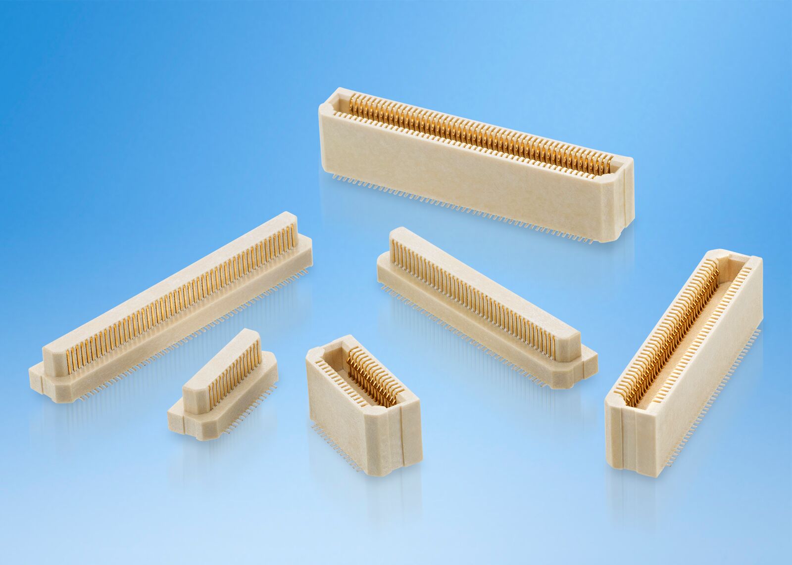 (Bildquelle: Harwin) Interessant ist, dass die Bauteile für die Verarbeitung per Pick&Place-Maschine optimiert
[c] for (i = 0; i < 64; i+=sizeof(unsigned int)) { *(unsigned int*)((unsigned int)&SDRAM_BASE_ADDR+i) = i; } for (i = 0; i < 64; i+=sizeof(unsigned int)) { if (*(unsigned int*)((unsigned int)&SDRAM_BASE_ADDR+i) != i) { return(i); } } [/c] Läuft perfekt
ist es jedenfals nicht... Denke nicht, das der LPC soviel Strom benötigt. Also weiter im Kapitel 85... und gefunden habe ich: 8534 Gedruckte Schaltungen 00 11 nur mit Leiterbahnen oder Kontakten (Mehrlagenschaltungen) 00 19 nur mit Leiterbahnen oder Kontakten (andere)
Capacitance Super Bright Red 45 pF VF=0V;f=1MHz Forward Voltage 3.7 5.0 VF [2] (DP) Super Bright Red (1.85) (2.5) V I=20mA Reverse Current 10 VR=5V R Super Bright Red uA (Per chip) (10) (VR =5V) Notes: 1.Wavelength: +/-1nm. 2. Forward Voltage: +/-0.1V. 3. Wavelength value is traceable to the CIE127-2007 compliant
discovery-mit-ethernet.htm Zur Funktion: Ihr braucht ein STM32 Discovery Board mit dem STMF4BB Base Board und einen Test-PC dessen IP Adresse ihr statisch auf z.B 192.168.0.100 konfiguriert (Subnetz 255.255.255.0 und STD-Gateway 192.168.2.1). Verbindet beide Stellen über zwei Patchkabel mit einem
Hallo Peter, vielen Dank für dein Projekt, werde es gleich mal ausprobieren. Habe mir neben dem BaseBoard auch das LCD gekauft. Hast du das schon einmal ausprobiert? Habe unter Atollic ein Beispiel zur Kalibrierung ans laufen bekommen. BMPs anzeigen läuft auch. Bin gerade dabei die Embedded GUI
and ±20 ppm Available • Operating Voltages +5.0Vdc or +3.3Vdc • Operating Temperature to -40°C to +85°C • Output Enable Standard • Tape & Reel Packaging • RoHS/Green Compliant (6/6) APPLICATIONS Applications for Model CB3 and CB3LV include digital video, networking equipment, wireless communications,
1.2 Advantages & special features: No EMI (Piezo ceramics) Balanced sine wave output, ultra low > 85% High efficiency harmonic current noise Inflammability (no liability) Short start up time, extended CCFL Wide range no flicker dimming lifespan One size fits all Open lamp and short circuit protection
1.2 Advantages & special features: No EMI (Piezo ceramics) Balanced sine wave output, ultra low > 85% High efficiency harmonic current noise Inflammability (no liability) Short start up time, extended CCFL Wide range no flicker dimming lifespan One size fits all Open lamp and short circuit protection
Dort bearbeiten. 9. Verstehen von: #define UART_CLKDIV( i ) (REG_UART_BASE( i ) + 0x14) #define UART_CLKDIV_CNT 0x000FFFFF #define UART_CLKDIV_S 0
bestellen, ist für Euch auch günstigerer Versand. http://www.amazon.de/s/ref=nb_sb_noss?__mk_de_DE=%C3%85M%C3%85%C5%BD%C3%95%C3%91&url=search-alias%3Daps&field-keywords=esp8266+radino&rh=i%3Aaps%2Ck%3Aesp8266+radino Die Bestellungen die bis 14.00Uhr reinkommen, versenden wir am gleichen Tag. Grüße,
, shorting the base of the 2N5812 to When the Hall switch is turned ON, 9 mA of base current flows into ground and turning it OFF. This allows: the 2N5811, thereby saturating it and allowing it to supply 80 mA of current
, shorting the base of the 2N5812 to When the Hall switch is turned ON, 9 mA of base current flows into ground and turning it OFF. This allows: the 2N5811, thereby saturating it and allowing it to supply 80 mA of current
, shorting the base of the 2N5812 to When the Hall switch is turned ON, 9 mA of base current flows into ground and turning it OFF. This allows: the 2N5811, thereby saturating it and allowing it to supply 80 mA of current
, shorting the base of the 2N5812 to When the Hall switch is turned ON, 9 mA of base current flows into ground and turning it OFF. This allows: the 2N5811, thereby saturating it and allowing it to supply 80 mA of current
, shorting the base of the 2N5812 to When the Hall switch is turned ON, 9 mA of base current flows into ground and turning it OFF. This allows: the 2N5811, thereby saturating it and allowing it to supply 80 mA of current
, shorting the base of the 2N5812 to When the Hall switch is turned ON, 9 mA of base current flows into ground and turning it OFF. This allows: the 2N5811, thereby saturating it and allowing it to supply 80 mA of current
, shorting the base of the 2N5812 to When the Hall switch is turned ON, 9 mA of base current flows into ground and turning it OFF. This allows: the 2N5811, thereby saturating it and allowing it to supply 80 mA of current
= 0 ; i < count ; i++) OneWire__write(buf[i], 0); if (!power) { noInterrupts(); DIRECT_MODE_INPUT(baseReg, bitmask); DIRECT_WRITE_LOW(baseReg, bitmask); interrupts(); } } // // Write a byte. The writing code uses the active drivers to raise the // pin high, if you need power after the write (e.g. DS18S20
C-grade: 58mA (@70ns) operating current 0.45uA at 3.0V/25 oC and maximum access time of 55ns at 3.0V/85 C. o I -grade: 60mA (@70ns) operating current Easy memory expansion is provided by an active LOW chip enable 2.0uA (Typ.) CMOS standby current (CE) , and active LOW output enable (OE) and three-state
@ Carsten: Die "85" ist normal beim ersten Einlesen. Ist auch im Datenblatt so beschrieben.
hap-configserver\t' Error: Can't open file Error: 'C:\svn\bin\hap-configserver\t\.svn\tmp\text-base\controller_test.t.svn-base': Error: Das System kann die angegebene Datei nicht finden. [/code] Man kann das Problem zwar durch manuellen Checkout: Datei-für-Datei umschiffen, aber vielleicht
T EREFSTEN=1 32 kHz 3 500 — nA –40 to 85°C 9 T IREFSTEN=1 32 kHz 70 — μA –40 to 85°C 10 T TPM PWM 100 Hz 12 — μA –40 to 85°C 11 T Low power SCI, SPI, or IIC 300 bps 15 — μA –40 to 85°C 12 T RTC using LPO 1 kHz 200 — nA –40 to 85°C mode adders
right Channel deskew -1 ms to +1 ms range Time scale accuracy (internal reference) Horizontal time base setting ± ((Horizontal time base setting) *(0.4 + 0.5* years since calibration) ppm (External reference clock = off) 2,3,4,5 Delta-time measurement accuracy 9064 4.8 20 Absolute averaging disabled 9104
printing, no width, the same record length at all time other color or monochrome digital storage base settings, advanced triggers to isolate oscilloscope offers as much flexibility signals of interest, and 11 standard auto- and ease of data transfer for the price. matic measurements on all models. Their
1. Normalized total power dissipation as a (1) Capped at 120A due to package function of mounting base temperature Fig. 2. Continuous drain current as a function of mounting base temperature BUK962R5-60E All information provided in this document is subject to legal diNexperia B.V. 2017. All rights reserved
