-
Datei
Lambdacontroller_ai_claude.txt
12.49, 12.53, 12.57, 12.61, 12.65, 12.68, 12.72, 12.76, 12.80, 12.84, 12.87, 12.91, 12.95, 12.99, 13.03, 13.06, 13.10, 13.14, 13.18, 13.21, 13.25, 13.29, 13.33, 13.36, 13.40, 13.44, 13.48, 13.51, 13.55, 13.59, 13.63, 13.67, 13.70, 13.74, 13.78, 13.82, 13.85, 13.89, 13.93, 13.96, 14.00, 14.04, 14.08,
in „Bosch CJ125 mit AVR AT90CAN64“ · Mikrocontroller und Digitale Elektronik ·
-
PDF
Messdaten.pdf
Sonne bulk 11.00 25,8V 240W Sonne bulk 12.00 26,0V 220W Sonne bulk 13.00 26,2V 220W Sonne bulk 13.30 24,2V Pumpe an 13.37 25,4V Pumpe aus 14.00 26V 210W Sonne bulk 15.00 26,0V 200W Sonne bulk 16.00 26,0V 110W Sonne bulk Tagesleistung: 56Ah 1,4KWh 13.05.15 11.00 Batterywatercheck
in „problem bei ladung der batterien durch PV“ · Analoge Elektronik und Schaltungstechnik ·
-
PDF
3DSanner_Stromlaufplan1.pdf
SDCARD_D1 P$139 PC9 PG6 P$109 SDCARD_D3 P$140 PC10 PG5 P$108 A14 GND SDCARD_CLK P$141 PC11 PG4 P$107 A13 PC13 P$8 PC12 PG3 P$106 A12 PC13 PG2 P$67 A11 PG1 P$66 A10 PG0 I/O2 P$142 PD0 PH15 P$130 I/O3 P$143 PD1 PH14 P$129 DCMI_D4 SDCARD_CMD P$144 PD2 PH13 P$128 SDCARD_D2 P$145 PD3 PH12 P$89 DCMI_D3 FSMC_NOE
in „STM32 Boot0 Problem“ · Mikrocontroller und Digitale Elektronik ·
-
PDF
STM32_Breakout_Assembly.pdf
PB14 PC11 PIIC10105210 / I2S3_CK USART1_RX / PA10 PIIC101044 PA11 12 PIX101013NPA4 12 PIX100013 PB13 PC12 PIIC10105311 / SPI3_MISO USART1_CTS / PA11 PIIC101045 PA12 14 PIX101014NPA5 14 PIX100014 PB12 PIIC1010PC13 / RTC3_SD JTMS-SWDIO / PA13 PIIC101046 TMS 15 PIX101015NPA6 15 PIX100015 PB11 COQ1 PIIC1010PC14
in „[V] STM32 Breakoutboard passend für Breadboard, tolle sache!“ · Markt ·
-
PDF
CONTACTORS.pdf
lamps Fluorescent tubes Compact fluo lamp with 5W 11 15 17 27 49 76 T5 double - uncompensated 2 x 18W 13 20 25 40 50 78 external electronic ballas7W 11 15 17 27 49 76 2 x 20W 12 19 24 38 50 78 9W 9 13 16 26 40 63 2 x 36W 12 15 19 30 44 69 11W 9 13 16 26 40 63 2 x 40W 10 13 16 26 40 63 15W 7 11 14 22 36
in „Kontaktfestbrennen durch viele LED?“ · Haus & Smart Home ·
-
PDF
Protokoll.pdf
= von PC an Tastatur XXX = Aktion die Ausgeführt wurde Spannungsversorgung wieder angeschlossen 14:13:39.92 [RX] - AA Selbsttest bestanden Befehl „RESTET“ an Tastatur gesendet 14:13:47.04 [TX] - FF 14:13:47.06 [RX] - FA ACKNOWLEDGE AA Selbsttest bestanden Befehl „RESTET“ an Tastatur gesendet 14:13:48.19
in „Tastaturschnittstelle“ · Mikrocontroller und Digitale Elektronik ·
-
PDF
Vishay_Diode_Marking.pdf
brown RGL41J red green BYM12-400 green yellow RGL41K red blue BYM12-50 green gray RGL41M red violet BYM13-20 orange gray SGL41-20 orange gray BYM13-30 orange red SGL41-30 orange red BYM13-40 orange orange SGL41-40 orange orange BYM13-50 orange yellow SGL41-50 orange yellow BYM13-60 orange green SGL41-60
in „Unbekanntes Bauteil“ · Mikrocontroller und Digitale Elektronik ·
-
PDF
marking.pdf
brown RGL41J red green BYM12-400 green yellow RGL41K red blue BYM12-50 green gray RGL41M red violet BYM13-20 orange gray SGL41-20 orange gray BYM13-30 orange red SGL41-30 orange red BYM13-40 orange orange SGL41-40 orange orange BYM13-50 orange yellow SGL41-50 orange yellow BYM13-60 orange green SGL41-60
in „Suche Datenblatt zu S422“ · Mikrocontroller und Digitale Elektronik ·
-
PDF
Thermoelement.pdf
11,170 11,304 11,439 11,574 11,710 1100 11,846 11,983 12,119 12,257 12,394 12,532 12,669 12,808 12,946 13,085 1200 13,224 13,363 13,502 13,642 13,782 13,922 14,062 14,202 14,343 14,483 1300 14,624 14,765 14,906 15,047 15,188 15,329 15,470 15,611 15,752 15,893 1400 16,035 16,176 16,317 16,458 16,599 16,741
in „Wie funktioniert Thermosensor in Heizofen“ · Haus & Smart Home ·
-
PDF
marking.pdf
brown RGL41J red green BYM12-400 green yellow RGL41K red blue BYM12-50 green gray RGL41M red violet BYM13-20 orange gray SGL41-20 orange gray BYM13-30 orange red SGL41-30 orange red BYM13-40 orange orange SGL41-40 orange orange BYM13-50 orange yellow SGL41-50 orange yellow BYM13-60 orange green SGL41-60
in „Suche die Bezeichnung eines Bauteils“ · Analoge Elektronik und Schaltungstechnik ·
-
PDF
88912_Marking_Diodes_Vishay-061201.pdf
brown RGL41J red green BYM12-400 green yellow RGL41K red blue BYM12-50 green gray RGL41M red violet BYM13-20 orange gray SGL41-20 orange gray BYM13-30 orange red SGL41-30 orange red BYM13-40 orange orange SGL41-40 orange orange BYM13-50 orange yellow SGL41-50 orange yellow BYM13-60 orange green SGL41-60
in „Bauteil identifizieren diode, SMC, "G DE 47"“ · Mikrocontroller und Digitale Elektronik ·
-
PDF
Sager_D87P_Service_Manual_Part4.pdf
-P VSS R14 L8 VDDR1 A V18 VDDC VSS R13 J24 VDDR1 VDDC AC13 8000mA V17 VDDC CENTER VSS R12 J23 AD13 V14 T13 J8 VDDR1 VDDC AD15 C128 V13 VDDC ARRAY VSS T14 J7 VDDR1 VDDC AC15 C624 C617 C613 C626 C601 C602 C612 C603 C599 C641 V12 VDDC VSS T15
-
PDF
Thomson-Tantal.pdf
09 4.70 02 03 04 05 05 08 11 6.80 03 04 05 06 07 09 11 10 04 05 07 08 09 10 12 15 05 06 09 10 10 12 13 22 06 08 10 11 12 13 13 33 08 09 11 12 13 14 – 47 09 11 12 13 14 15 – 68 11 12 13 14 15 – – 100 12 13 14 15 – – – 150 13 14 15 – – – – 220 14 15 15 – – – – 330 15 15 – – – – – Value/Voltage combinations
in „Defekte Diode Werte?“ · Analoge Elektronik und Schaltungstechnik ·
-
Datei
email.txt
target="_blank"/></map><div class="ctext1"><img src="http://www.reichelt.de/bilder/Newsletter/2011/13-2_katalog/reiter.jpg" usemap="#Head" border="0" alt="Head" /></div> <div style=""></div></div> <div style="float:left;text-align:left;clear:both;background-color:#E1E4F7;width:100%"> <div style="float
in „Hilfe: Outlook 2007 SP2 zeigt in Emails keine Bilder an“ · PC Hard- und Software ·
-
PDF
schaltplan.pdf
P7.5 C8 P4.1 A8 B9 P7.6 C9 P4.2 A9 B10 P7.7 C10 P4.3 A10 B11 P6.1 C11 P4.4 A11 B12 P6.2 C12 P4.5 A12 B13 SDA C13 P4.6 A13 B14 SCL C14 P4.7 A14 B15 P6.5 C15 P1.0 A15 B16 P6.6 C16 P1.1 A16 B17 P6.7 C17 P1.2 A17 B18 P5.0 C18 P1.3 A18 D7 B19 P5.1 C19 P1.4 A19 D6 B20 P5.2 C20 P1.5 A20 D5 B21 P5.3 C21 P1.6 A21
in „80C537 System“ · Mikrocontroller und Digitale Elektronik ·
-
Datei
Messwerte_4809.txt
5362306 121 335.14ms 684484191 689846389 5362198 108 335.14ms 700571163 705933176 5362013 185 335.13ms 716656692 722018599 5361907 106 335.12ms 732744749 738106765 5362016 109 335.13ms 748832147 754194193 5362046 30 335.13ms 764920537 770283144 5362607 561 335.16ms 781009797 786372486 5362689 82 335.17ms
in „Timer Overflow Counter - Wie richtig berücksichtigen?“ · Mikrocontroller und Digitale Elektronik ·
-
PDF
STM32F407ZG-board-schematic.pdf
33k 2k WP_E 33k PF12 A6 50 PF12/FSMC_A6 PE12/FSMC_D9/TIM1_CH3N5 D9 PE12 C85 C90 Close SD_CARDBOT PF13 A7 53 PF13/FSMC_A7 PE13/FSMC_D10/TIM1_CH36 D10 PE13 100nF 100nF WP 1 2 10 WP1 PF14 A8 54 PF14/FSMC_A8 PE14/FSMC_D11/TIM1_CH47 D11 PE14 U12 U13 14 WP2 2 PF15 A9 55 PF15/FSMC_A9 68 D12 PE15 2 CAMERA CONNECTOR
in „8Mbit/s Manchester Code codieren und decodieren mit STM32F407“ · Mikrocontroller und Digitale Elektronik ·
-
PDF
STM32F407ZG-board-schematic.pdf
33k 2k WP_E 33k PF12 A6 50 PF12/FSMC_A6 PE12/FSMC_D9/TIM1_CH3N5 D9 PE12 C85 C90 Close SD_CARDBOT PF13 A7 53 PF13/FSMC_A7 PE13/FSMC_D10/TIM1_CH36 D10 PE13 100nF 100nF WP 1 2 10 WP1 PF14 A8 54 PF14/FSMC_A8 PE14/FSMC_D11/TIM1_CH47 D11 PE14 U12 U13 14 WP2 2 PF15 A9 55 PF15/FSMC_A9 68 D12 PE15 2 CAMERA CONNECTOR
in „Problem: SPI Remap am STM32F407ZG“ · Mikrocontroller und Digitale Elektronik ·
-
PDF
0279834120.pdf
7.2 15 /7.3 06 /7.23 4 /7.3 3 4 /7.2 3 4 7 16 /7.3 3 4 5 05 5 6 5 6 5 6 5 6 08 /7.2 /7.3 /7.2 /7.3 5 13 14 13 14 13 14 13 14 7 5 21 22 421 22 721 22 21 22 +Kt= +Kopfträger/ cross girder of bridge/sommier Changes Date Name Date Name Copyright Stromlaufplan / circuit diagram = 09.02.16 Huhnd. Editor 07.07.08
in „Kran Motor polumschaltbar Klemmenbrett Belegung unklar“ · Haus & Smart Home ·
-
PDF
DM8603EP.pdf
. Bandwidth control with ingress or egress is combined,thethresholddefinedinREG08/09/0Ah.15h.[3:0] 13 81h.[13] PSE,RW 0b STORM_UUP 91h.[13] Broadcast Storm Enable for Unlearned Unicast Packets A1h.[13] 0: Disable 1: Enable 12 81h.[12] PSE,RW 0b STORM_MP 91h.[12] Broadcast Storm Filtering for Multicast
in „2 Port Switch IC wie in IP telefonen?“ · Mikrocontroller und Digitale Elektronik ·
-
PDF
DM8603EP.pdf
. Bandwidth control with ingress or egress is combined,thethresholddefinedinREG08/09/0Ah.15h.[3:0] 13 81h.[13] PSE,RW 0b STORM_UUP 91h.[13] Broadcast Storm Enable for Unlearned Unicast Packets A1h.[13] 0: Disable 1: Enable 12 81h.[12] PSE,RW 0b STORM_MP 91h.[12] Broadcast Storm Filtering for Multicast
in „[V] DM8203 & DM8603“ · Markt ·
-
PDF
trc101.pdf
write operations. The TRC101 uses word writes so the nCS pin(3) should be pulled low for 16 bits. Rev13 11 Figure 3. SPI Interface Timing Rev13 12 4. Control and Configuration Registers POR Bit Bit Bit Bit Bit Bit Bit Bit Bit Bit Bit Bit Bit Bit Bit Bit Value 15 14 13 12 11 10 9 8 7 6 5 4 3 2 1 0 STATUS
in „bidirektionale RS232 Funkbrücke mit RFM12“ · Projekte & Code ·
-
PDF
2016_03_vermoegen_finanzen_private_haushalte.pdf
6 41 200 23 600 3 29 400 9 600 . . . Nichterwerbstätige) 12 65 500 29 400 9 47 700 13 700 5 62 800 32 600 Rentner 13 71 600 30 200 10 52 000 14 200 5 70 100 43 700 Pensionäre 24 56 800 24 400 21 44 300 13 800 9 52 100 13 600 Schulbildung der Referenzperson ohne Schulabschluss . . . .
in „Euer finanzieller Puffer?“ · Ausbildung, Studium & Beruf ·
-
Datei
DC_3840EEprom_cut.lst
138E E5 4A mov a, 4Ah 1390 04 inc a 1391 12 13 DA lcall 13DAh 1394 40 10 jc 13A6h 1396 12 13 EB lcall 13EBh 1399 F5 30 mov 30h, a 139B 12 13 FE lcall 13FEh 139E 12 14 0E lcall 140Eh 13A1 C2 06 clr 20h.6 13A3 D0 07 pop 07h 13A5 22 ret 13A6 DF CF djnz
-
PDF
SARA-G3_DataSheet__UBX-13000993_.pdf
> = 2,..,13 T3 I2S_CLK low time 1.933 1.953 µs <I2S_mode> = 2,..,13 I2S_WA period 125.0 µs <I2S_mode> = 2,..,13 I2S_WA frequency 8 kHz <I2S_mode> = 2,..,13 T4 I2S_TX invalid before I2S_CLK low end 24 ns <I2S_mode
in „GSM-Modul (SIM908) nur analoge Ausgänge für Anruf?“ · HF, Funk und Felder ·
-
PDF
eGC.pdf
PAIC10A12 4PAR8PAI0 90AIC70E3PAIC40E2PAIC40E10K1PAIC20K2PAIC20COR2PAR201PAR20PAC480APACPAC46015C10Y13 PAIC10W13 PAIC10V13PAIC10U13PAIC10T13 PAIC10R13 PAIC10P13 PAIC10N13 PAIC10M13PAIC10L13PAIC10K13PAIC10J13 PAIC10H13 PAIC10G13 PAIC10F13PAIC10E13PAIC10D13PAIC10C13PAIC10B13 PAIC10A13 PL41 P A42P61 PAIC40PAIC40D82AIC40D2PAIPAPAC8901AC89022PAIC20M3PAIC20MPAIC10AB15P31C10A15PAIC10Y5PAIC10W5PAIC10V15PAIC10U15PAIC10T15PAIC10R5PAIC10P5PAIC10N5PAIC10M15PAIC10L15PAIC10K15PAIC10J15PAIC10H5PAIC10G5
in „[Suche] Interessierte(n) an Projekt (ARM/FPGA)“ · Mikrocontroller und Digitale Elektronik ·
-
PDF
EPSON_GLCD.pdf
6 0 1 1 6 1 1 2 3 1 5 42 VD7 1 2 3 1 2 C S S + 43 VD6 N N N E E V V E WR/ 14 GND 44 VD5 S S R RD/ 13 45 VD4 CE/ 19 IC1 46 VD3 C/D/ 20 47 VD2 32 VCC NC 1 48 VD1 D0 22 31 A15 A16 2 49 VD0 D1 23 30 CE2 A14 3 D2 24 29 WE/ A12 4 50 A15 D3 25 28 A13 A7 5 51 A14 D4 26 zum GLCD 27 A8 A6 6 52 A13 D5 27 SV2 26
in „G-LCD bei Pollin“ · Mikrocontroller und Digitale Elektronik ·
-
PDF
REV4.1_sch.pdf
CMOS_D3 5 A4 B4 15 DB11 SCK 3 PB7 (SCK) PA7 (ADC7) 30 LCD_RD CMOS_D4 6 A5 B5 14 DB12 CMOS_D5 7 A6 B6 13 DB13 RXD 9 PD0 (RXD) PC0 (SCL) 19 DB8 CMOS_D6 8 12 DB14 TXD 10 20 DB9 CMOS_D7 9 A7 B7 11 DB15 CMOS_VSYNC 11 PD1 (TXD) PC1 (SDA) 21 DB10 MISO A8 B8 TP_INT 12 PD2 (INT0) PC2 (TCK) 22 DB11 10 PD4 13 PD3
in „SCCB cameramodul XCLK-Problem“ · Mikrocontroller und Digitale Elektronik ·
-
PDF
TableClonesEn.pdf
zener diodes (<5V), No firmware +9V ≥15-20$ 8Mhz 128x64 port PC5 resistors, capacitors, 1.13к or chokes, inductors 1.41m M328Kit+TFT(AY-AT) Transistors, diodes, Firmware diode assemblies, Yes, 1.12к mod., LEDs, thyristors, triacs, SRV05-4 possible LCD TFT 7550, +9V, ATMega328, 1.8" SPI, TL431
-
PDF
LA3401_Datenblatt.pdf
mode 1. Muting time Muting is turned ON for a certain period of time fixed by external capacitor C13. Fig. 12 shows the relation between the muting time and C13. 2.Values ofAM/FM input coupling capacitors (C1, C2) and value of C13 If muting is released before the DC voltage on the AM input (pin 1) or
in „Fehlersuche Radio“ · Analoge Elektronik und Schaltungstechnik ·
-
PDF
A500_ETV570G2DHU.pdf
electricity of the electrically-powered driver or the vacuum cleaner may destroy the module . 13.7.5 Don’t give external shock. 13.7.6 Don’t apply excessive force on the surface. 13.7.7 Liquid in LCD is hazardous substance. Must not lick and swallow. When the liquid is attach to your, skin, cloth etc. Wash it out thoroughly and immediately. 13.7.8 Don’t operate it above the absolute maximum rating. 13.7.9 Storage in a clean environment, free from dust, active gas, and solvent. 13.7.10 Store without any physical load. 13.7.11 Rewiring: no more
in „VGA Grafikkarte mit AVR und 8MB SDRAM“ · Projekte & Code ·
-
PDF
K2000-schematics.pdf
D15 A2/DRAMA1 13 A2 3 A6 D6 19 D15 4 3 2 1 3 3 3 U156 2 1 0 D14 56 D14 A3/DRAMA2 12 A3 25 A7 D7 4 3 2 1 3 3 3 D13 57 D13 A4/DRAMA3 11 A4 24 A8 1 1 1 P C P 1 2 5 6 P C P 7 D12 58 D12 A5/DRAMA4 10 A5 21 A10 GND 14 A A
in „Kalibrierung Keithley 2000 Multimeter“ · Mikrocontroller und Digitale Elektronik ·
-
PDF
DE_16DE0001_TECHNIK_LEITUNGSSCHUTZSCHALTER.pdf
LS-Schalter 2000 ~ 50 Hz ~ 50 Hz I 1,13 In 1,13 In 1,13 In 1,13 In 6000 1 t1 400 DC 2 It2 1,45 In 1,45 In 1,45 In 1,45 In r l 200 3 Irm1 3 In 3 In 5 In 5 In h 100 s c . 60 AC 4 Irm2 5 In 7,5 In 10 In 15 In n t e 40 t u n 20 쓒 e hc i 10 L s
in „Fi-Schutzschalter nur für die Hälfte der Wohnung?“ · Haus & Smart Home ·
-
PDF
DE_20DE0001_TECHNIK_LEITUNGSSCHUTZSCHALTER.PDF
Auslösecharakteristik C 10000 6 kA 6000 2 AC DC AC DC 3600 LS-Schalter ~ 50 Hz ~ 50 Hz 2000 1000 1 It1 1,13 In 1,13 In 1,13 In 1,13 In 600 400 DC 2 It2 1,45 In 1,45 In 1,45 In 1,45 In 200 100 3 Irm1 3 In 3 In 5 In 5 In 60 4 I 5 In 7,5 In 10 In 15 In k 40 AC rm2 e 20 쓒 i e 16 Z 4 Tabelle 2 Z 2 Auslösung Auslöse
in „Heizstrahler Schalterkontakt brennt fest“ · Analoge Elektronik und Schaltungstechnik ·
-
PDF
TDA1023.pdf
SYMBOL PARAMETER CONDITIONS MIN. TYP. MAX. UNIT Supply VCC internally stabilized supply voltage at 12 13.7 15 V 16 = 10 mA VCC/ I16 variation wi16 I − 30 − mV/mA 16 supply current a16-13 11 to 16 V; pins 4 and 5 open − − 6 mA 10 = 1mA; f = 50 Hz; pin 11 open; V6-13> V7-13 pins 4 and 5 grounded − − 7.1 mA
in „TDA1023 oder Ersatz“ · Analoge Elektronik und Schaltungstechnik ·
-
PDF
ZX05-42MH_.pdf
Coaxial Frequency Mixer ZX05-42MH+ Level 13 (LO Power +13 dBm) 5 to 4200 MHz Maximum Ratings Features Operating Temperature -40°C to 85°C • rugged construction Storage Temperature -55°C to 100°C • small size CASE STYLE: FL905 RF Power 200mW •
in „Wie funktioniert diese Mischerschaltung?“ · HF, Funk und Felder ·
-
Datei
Menu.c
text = "Ebene 1.1"; menu[menu11].previous = menu1; menu[menu11].next = menu11; menu[menu11].up = menu13; menu[menu11].down = menu12; menu[menu11].fp = func_menu11; menu[menu12].text = "Ebene 1.2"; menu[menu12].previous = menu1; menu[menu12].next = menu12; menu[menu12].up = menu11; menu[menu12].down = menu13; menu[menu12].fp = func_menu12; menu[menu13].text = "Ebene 1.3"; menu[menu13].previous = menu1; menu[menu13].next = menu13; menu[menu13].up = menu12; menu[menu13].down = menu11; menu[menu13].fp = func_menu13; menu[menu2].text = "Ebene 2"; menu
in „Pointer und ihre Tücken“ · Mikrocontroller und Digitale Elektronik ·
-
PDF
cycloneIII_3c120_dev_reference_manual.pdf
10 LCD data bus bit 4 2.5 V LCD_DATA4 AE2 J13 pin 11 LCD data bus bit 5 2.5 V LCD_DATA5 V5 J13 pin 12 LCD data bus bit 6 _or SCLK 2.5 V LCD_DATA6 V6 J13 pin 13 LCD data bus bit 7 _or SDATA 2.5 V LCD_DATA7 AB3 J13 pin 28 Parallel interface selection
in „[V]erkaufe: Cyclone III FPGA Video Developement Board“ · Markt ·
-
PDF
Manual_netX_Program_Reference_Guide_Rev02_GB.pdf
HS_EVENT15 Handshake event 15 interrupt enable R 0 14 HS_EVENT14 Handshake event 14 interrupt enable R 0 13 HS_EVENT13 Handshake event 13 interrupt enable R 0 12 HS_EVENT12 Handshake event 12 interrupt enable R 0 11 HS_EVENT11 Handshake event 11 interrupt enable R 0 10 HS_EVENT10 Handshake event 10 interrupt
in „netX500 mit ARM-Kern“ · Mikrocontroller und Digitale Elektronik ·
-
PDF
MCU_-_HR8P506_Datasheet_e.pdf
_00000000_00000000B 31 30 29 28 27 26 25 24 23 22 21 20 19 18 17 16 Reserved 15 14 13 12 11 10 9 8 7 6 5 4 3 2 1 0 Reserved DATA<13:0> - bit31-14 - - PB output level DATA<13:0> bit13-0 R/W 0: Output low level 1: Output high level PB Output Data Bit Set Register (GPIO_PBDATABSR) Offset
in „Re - Programmierung eines Cortex M0“ · Mikrocontroller und Digitale Elektronik ·
-
PDF
LCD.pdf
0.1UF 0.1UF 0.1UF 0.1UF 0.1UF 9 10 50V 50V 50V 50V 50V Y+ 3Y+ DIN14 MOSI DB07 DB07 DB06 DB06 X- 4 13 DB09 11 12 DB08 X- BUSY DB09 DB08 Y- 5 12 MISO DB11 13 14 DB10 Y- DOUT DB11 DB10 6 11 /INT DB13 15 DB12 16 DB12 GND /INT DB13 GND 7IN3 VCC210 DB15 17 DB15 DB14 18 DB14 8IN4 VREF9 RS 19 RS /LCD_CS 20
in „8 Bit Ansteuerung SSD1289 Display320x240“ · Mikrocontroller und Digitale Elektronik ·
-
Datei
ESC8266_2.txt
":"2023-12-13T21:07:21","Uptime":"0T00:01:29","UptimeSec":89,"Heap":20,"SleepMode":"Dynamic","Sleep":50,"LoadAvg":19,"MqttCount":1,"Wifi":{"AP":1,"SSId":"Experimentelles Atomlabor","BSSId":"2C:91:AB:B7:E0:2E","Channel
in „eBZ Stromzähler liefert plötzlich keinen Verbrauch mehr“ · Haus & Smart Home ·
-
 Bild
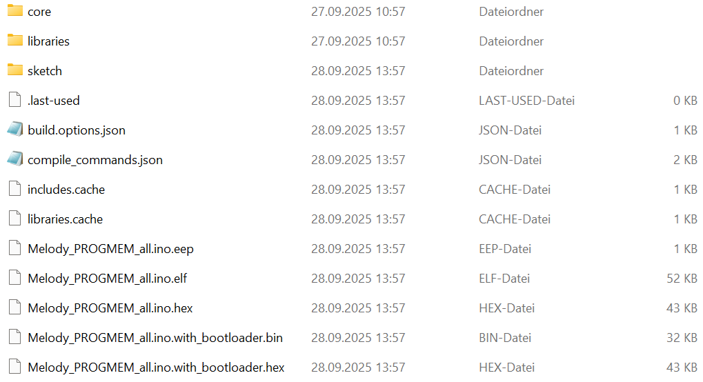
Dateimanager mit Arduino-Build-Dateien
core 27.09.2025 10:57 Dateiordner libraries 27.09.2025 10:57 Dateiordner sketch 28.09.2025 13:57 Dateiordner .last-used 28.09.2025 13:57 LAST-USED-Datei 0 KB build.options.json 28.09.2025 13:57 JSON-Datei 1 KB compile_commands.json 28.09.2025 13:57 JSON-Datei 2 KB includes.cache 28.09.2025 13:57 CACHE-Datei 1 KB libraries.cache 28.09.2025 13:57 CACHE-Datei 1 KB Melody_PROGMEM_all.ino.eep 28.09.2025 13:57 EEP-Datei 1 KB Melody_PROGMEM_all.ino.elf 28.09.2025 13:57 ELF-Datei 52 KB Melody_PROGMEM_all.ino.hex 28.09.2025 13:57 HEX-Datei 43 KB
in „Arduino Uno R4: Besonderheiten und Abhilfen“ · Mikrocontroller und Digitale Elektronik · · Screenshots
-
 Bild
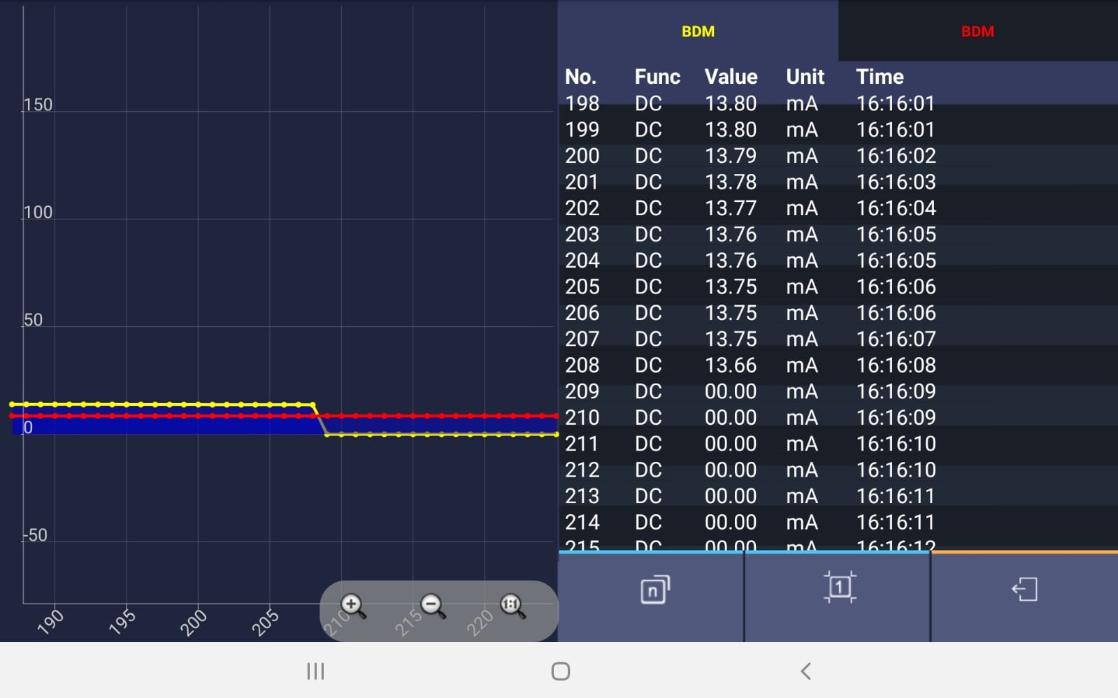
Messdaten einer Stromaufnahme in einer Tabelle und Diagramm
BDM Value Unit Time 198 DC 13.80 mA 16:16:01 199 DC 13.80 mA 16:16:01 200 DC 13.79 mA 16:16:02 201 DC 13.78 mA 16:16:03 202 DC 13.77 mA 16:16:04 203 DC 13.76 mA 16:16:05 204 DC 13.76 mA 16:16:05 205 DC 13.75 mA 16:16:06 206 DC 13.75 mA 16:16:06 207 DC 13.75 mA 16:16:07 208 DC 13.66 mA 16:16:08 209 DC 00.00 mA 16:16:09 210 DC 00.00 mA 16:16:09 211 DC 00.00 mA 16:16:10 212 DC 00.00 mA 16:16:10 213 DC 00.00 mA 16:16:11 214 DC 00.00 mA 16:16:11 215 DC 00.00
in „Baofeng UV-5R Ladespannung“ · HF, Funk und Felder · · Screenshots
-
PDF
Amplifiers_and_Comparators_-_Motorola.pdf
nA 2.0 10 0.05 25 4.0 10 〉 2.5 〉 18 Low Power, JFET Input P/626 TL071AC 200 pA 6.0 10 50 pA 50 4.0 13 〉 5.0 〉 18 Low Noise, JFET Input P/626 TL071C 200 pA 10 10 50 pA 25 4.0 13 〉 5.0 〉 18 Low Noise, JFET Input D/751 TL081AC 200 pA 6.0 10 100 pA 50 4.0 13 〉 5.0 〉 18 JFET Input P/626 TL081C 400 pA 15 10
in „AVR: Wechseln des Kanals mit automatischem Trigger“ · Mikrocontroller und Digitale Elektronik ·
-
PDF
slas272d.pdf
1. A . . P A P 3 3 3 3 2 /C P P . P P P P P 2 2 P P POST OFFICE BOX •DALLAS, TEXAS 75265 3 MSP430x13x, MSP430x14x MIXED SIGNAL MICROCONTROLLER SLAS272D – JULY 2000 – REVISED MARCH 2003 functional block diagrams MSP430x13x DV DV AV AV XIN XOUT/TCLK CC SS CC SS RST/NMI P1 P2 P3 P4 P5 P6 Rosc Oscillator
in „MSP430 Interrupt Port1“ · Mikrocontroller und Digitale Elektronik ·
-
PDF
18650_mWh.pdf
881 3463 3172 02:12:26 3,77 883 3470 3178 02:12:41 3,77 885 3476 3184 02:12:57 3,77 886 3483 3191 02:13:13 3,76 888 3489 3197 02:13:28 3,76 890 3495 3203 02:13:44 3,76 892 3502 3210 02:13:59 3,76 893 3508 3216 02:14:15 3,76 895 3515 3222 02:14:31 3,76 897 3522 3228 02:14:46 3,76 898 3528 3234 02:15:02
in „Leistung eines Li Akkus berechnen.“ · Analoge Elektronik und Schaltungstechnik ·
-
Datei
adressen_beschreiben.c
w243 w244 w245 w246 w247 w248 w249 w250 w251 w252 w253 w254 w read_ram 0 1 2 3 4 5 6 7 8 9 10 11 12 13 14 15 16 17 18 19 20 21 22 23 24 25 26 27 28 29 30 31 32 33 34 35 36 37 38 39 40 41 42 43 44 45 46 47 48 49 50 51 52 53 54 55 56 57 58 59 60 61 62 63 0 1 2 3 4 5 6 7 8 9 10 11 12 13 14 15 16 17 18 19
in „GLCD mit T6963-Controller und 8kRAM ansteuern klappt nicht“ · Mikrocontroller und Digitale Elektronik ·
-
PDF
STM32-P207-P407_rev_D.pdf
15 D6 PF12 A6 50 PF11/DCMI_12 PE11/FSMC_D8/TIM1_CH265 D9 PE12 3.3V 3.3V D 4 7 6 A7 20 A6 I/O6 16 PF13 A7 53 PF12/FSMC_A6 PE12/FSMC_D9/TIM1_CH3N66 D10 PE13 C85 C90 N L 1/ A7 I/O7 D7 PF13/FSMC_A7 PE13/FSMC_D10/TIM1_CH3 100nF 100nF 1 8 R8 A8 21 A8 I/O8 29 D8 3.3V PF14 A8 54 PF14/FSMC_A8 PE14/FSMC_D11/TIM1
in „Mit STM32F4 einen Laser ansteuern“ · Mikrocontroller und Digitale Elektronik ·
-
PDF
Aeternum_V1.pdf
2Q 17 A2 A2 10 A1 C11 25 /OE 3D 3Q A2 100n t PC2(ADC2/PCINT10) 26 D3_A3 5 4D 4Q 16 A3 A3 9 A3 I/O00 13 D0_A0 s 2 PC3(ADC3/PCINT11) /WE D4_A4 6 15 A4 A4 8 14 D1_A1 R C2 C3 PC4(ADC4/SDA/PCINT12) 27 SDA/2.1A D5_A5 7 5D 5Q 14 A5 A5 7 A4 I/O01 15 D2_A2 / 27p20 MHz PC5(ADC5/SCLPCINT13) 28 SCL/2.1A D6_A6 8 6D
in „CP/M auf ATmega88“ · Mikrocontroller und Digitale Elektronik ·