-
PDF
WM8731_WM8731L.pdf
variation of the frequency response in the pass-band region PD Rev 3.4 April 2004 w 51 WM8731 / WM8731L Production Data DAC FILTER RESPONSES 0.04 0 0.03 -20 0.02 B B 0.01 ( -40 ( s s n n 0 p p e e R -60 R -0.01 -0.02 -80 -0.03 -100 -0.04 0 0.5 1 1.5 2 2.5 3 0 0.05 0.1 0.15 0.2 0.25 0.3 0.35 0.4 0.45 0.5
in „Altera DE1 Board: Frage zu I2C Bus Adresse vom Audiocodec.“ · FPGA, VHDL & Co. ·
-
PDF
AudioCodec-WM8731_8731L.pdf
variation of the frequency response in the pass-band region PD Rev 4.0 February 2005 w 51 WM8731 / WM8731L Production Data DAC FILTER RESPONSES 0.04 0 0.03 -20 0.02 B B 0.01 ( -40 ( s s n n 0 p p e e R -60 R -0.01 -0.02 -80 -0.03 -100 -0.04 0 0.5 1 1.5 2 2.5 3 0 0.05 0.1 0.15 0.2 0.25 0.3 0.35 0.4 0.45 0.5
in „Elektret-Mikrofon-Verstärker-->Line-In mit assymmetrischer Vers.Sp.“ · Mikrocontroller und Digitale Elektronik ·
-
Datei
usb_vcp.c
. Example 'Hello-World' 48 65 00 00 6C 6C 00 00 6F 2D 00 00 57 6F 00 00 72 6C 00 00 64 ... H e l l o - W o r l d ... The copy routines have to pay attention of this and therefore no simple memcpy can be used. See also UMEM_SHIFT and UMEM_FAKEWIDTH defines. */ #define USB_RAM 0x40006000 #define EpCtrlLenId
in „STM32 USB Übertragungsproblem mit Code von S.F.“ · Mikrocontroller und Digitale Elektronik ·
-
Datei
Nur_Text_2.bas
Zeichen 'String zu Ende ? breq LCD_Write_String_99 ldi Temp_3, 8 'Offset in TabChr berechnen mov Accu_L, Temp_3 clr Accu_H mul Accu_L, Zeichen '..Offset + Anfangsadresse von TabChr ldi ZL, low(TabChr *2) ldi ZH, high(TabChr *2) add ZL, Accu_L adc ZH, Accu_H rcall LCD_Write_Chr Loadadr Locate_spalte , Z
in „Display mit Touchscreen bei Pollin?“ · Mikrocontroller und Digitale Elektronik ·
-
PDF
webench_design_1688335_26_232377900.pdf
479 ESR= 5.0 mOhm VDC= 100.0 V 2220 60mm2 IRMS= 6.45 A 5. Cinx TDK C2012X7R2A104K Cap= 100.0 nF 1 $0.03 Series= 285 ESR= 15.726 mOhm 0805 7mm2 VDC= 100.0 V IRMS= 0.0 A 6. Cout MuRata GRM21BR60J226ME39L Cap= 22.0 µF 1 $0.03 Series= X5R ESR= 9.0 mOhm 0805 7mm2 VDC= 6.3 V IRMS= 3.5 A 7. Cramp Yageo America
-
PDF
715G7312_PSU.pdf
! BEAD C9914 220PF 250V NR9901 3 4 1 2 1 2 ! ! ! C9911 NC9901 1.5R t T6.3AH 250V 47pF 250V ! C9902 L9904 2 ! L9903 470NF 275V L9905 18mH BD9901 ! 1 ! 18mH 4 3 1 2 2L9902 3 TS10P06G-04 CN9901 RV9901 C9901 1 2 2 L9901 3 ! ! 680V 470NF 275V ! ! 4 - + 1 AC 2P 1 2 4 3 1 NC/734 174-65-LS 4 3 1 NC/73G 174-
in „Phillips 55PUS6561/12 keine Hintergrundbeleuchtung“ · Analoge Elektronik und Schaltungstechnik ·
-
PDF
Report.pdf
Page 39of 96 802.11b CH6 0 -5 -10 -15 FCC CSE -20 -25 -30 B -35 d l -40 e -45 L -50 -55 -60 -65 -70 -75 -8.03 2 4 6 8 10 12 14 16 18 Frequency in GHz Note: The signal beyond the limit is carrier Spurious RF conducted emissions from 30MHz to 18GHz 0 -10 FCC CSE -20 -30
in „Wlan2Serial Modul für 5 euro“ · Mikrocontroller und Digitale Elektronik ·
-
PDF
HMC5883L_3-Axis_Digital_Compass_IC.pdf
prepared to up-size the capacitors to gain Low ESR characteristics. INTERNAL SCHEMATIC DIAGRAM HMC5883L 6 www.honeywell.com HMC5883L DUAL SUPPLY REFERENCE DESIGN SINGLE SUPPLY REFERENCE DESIGN www.honeywell.com 7 HMC5883L PERFORMANCE The following graph(s) highlight HMC5883L’s performance. Typical Noise
in „hmc5883l - Winkel berechnen?!“ · Mikrocontroller und Digitale Elektronik ·
-
PDF
HMC5883L_3-Axis_Digital_Compass_IC.pdf
prepared to up-size the capacitors to gain Low ESR characteristics. INTERNAL SCHEMATIC DIAGRAM HMC5883L 6 www.honeywell.com HMC5883L DUAL SUPPLY REFERENCE DESIGN SINGLE SUPPLY REFERENCE DESIGN www.honeywell.com 7 HMC5883L PERFORMANCE The following graph(s) highlight HMC5883L’s performance. Typical Noise
-
PDF
Layout.pdf
P 100.000mm Z C 2ZX54ZX712Z31C 411X2NC 03Z22N1 1 1 L X 5 7X3 X X 81ZX2N 82Z72NC 1 X X X X Z X 3Z 2ZX3C C CX X 021X2N 42ZX2NZX2C X R15R R C43C C X 1 P 2 Z X 6 X C C14Z Z 22N12N2 2ZX83N 12 C Z Z C X L 6 C18C C C 88 8 3 1 3 C39 C41C C X 3 R 3X
in „TPA3255, Fehler LED nach 1s“ · Analoge Elektronik und Schaltungstechnik ·
-
PDF
M202SD01LA.pdf
5 4-5 1-6 2-6 3-6 4-6 5-6 4th 5-5 1-6 2-6 3-6 4-6 5-6 1-7 2-7 1-7 2-7 3-7 4-7 5-7 5th 3-7 4-7 5-7 "L" "L" "L" "L" "L" (a) Character Font (b) Font Data Example of write-in character "1" in UF0. Control and data strings 03H, 1BH, 23H, 08H, 42H, 11H, C0H. bit 7 6 5 4 3 2 1 0 1st L L H L L L H H 2nd L L L L H L L L byte 3rd L H L L L L H L 4th L L L H L L L H 5th H H L L L L L L "H" : Turn On "L" : Turn Off Fig.1 Defining User's font It is recommended to store these definable characters at the initializing
in „Hat schon jemand was mit dem FUJITSU VF60 Display gemacht?“ · Mikrocontroller und Digitale Elektronik ·
-
Datei
lspci.txt
00:00.0 Host bridge: Intel Corporation 82855PM Processor to I/O Controller (rev 03) 00:01.0 PCI bridge: Intel Corporation 82855PM Processor to AGP Controller (rev 03) 00:1d.0 USB controller: Intel Corporation 82801DB/DBL/DBM (ICH4/ICH4-L/ICH4-M) USB UHCI Controller #1 (rev 01) 00:1d.1 USB controller: Intel Corporation 82801DB/DBL/DBM (ICH4/ICH4-L/ICH4-M) USB UHCI Controller #2 (rev 01) 00:1d.2 USB controller: Intel Corporation 82801DB/DBL/DBM (ICH4/ICH4-L/ICH4-M) USB UHCI Controller #3 (rev 01) 00:1d.7 USB controller: Intel Corporation 82801DB
in „Limux:: Netzwerk und WLAN futsch.“ · PC Hard- und Software ·
-
Datei
dds-pll.asm
; out tccr0B,tmp sei ; global enable interrupts ret ;*********************** divplus1: ; setup div1L div1H as divider +1 value ldi div1L,1 ldi div1H,0 add div1L,divL adc div1H,divH ; setup higher divider as lower + 1 ret ;***************** pllmode: ; entry point pll setup ldi tmp, RAMEND out SPL, tmp
in „PLL mit Atmega8 läuft + Fragen!“ · Mikrocontroller und Digitale Elektronik ·
-
 Bild
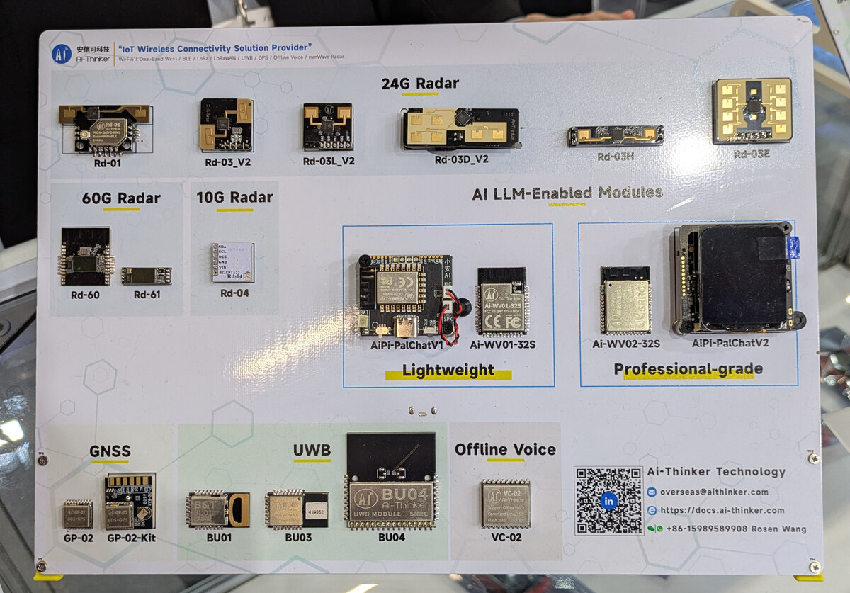
Übersicht verschiedener Ai-Thinker IoT-Module
Ai-Thinker "IoT Wireless Connectivity Solution Provider" 24G Radar Rd-01 Rd-03_V2 Rd-03L_V2 Rd-03D_V2 Rd-03H Rd-03E 60G Radar Rd-60 Rd-61 10G Radar Rd-04 AI LLM-Enabled Modules AiPi-PalChatV1 Ai-WV01-32S Ai-WV02-32S AiPi-PalChatV2 Lightweight Professional-grade GNSS GP-02 GP-02-Kit BU01 BU03 BU04 UWB MODULE UWB VC-02 Offline Voice Ai-Thinker Technology overseas@ai-thinker.com https://docs.ai-thinker.com +86-15989589908 Rosen Wang
in „EmbeddedWorld 2026, Catch-All – Bauteile, Stromversorgungen, Meshnetze uvam“ · Mikrocontroller und Digitale Elektronik · · Fotos

-
PDF
Dds-1.pdf
Digital-Analog-Wandler mit 4 Bit Auflos¨ng Nach [1, S. 636f] errechnet sich die Ausgangsspannung wie folgt: Uref R L Ua= 16 ·R + R · Z L R L ist der Lastwiderstand am Ausgang des DA-Wandlers, also der Eingangs- widerstand des am Ausgang angeschlossenen Gerate¨. Dieser sollte im Vergleich zu R mog¨ichst hoch sein, da
in „Frage zu AVR DDS Funktionsgenerator“ · Mikrocontroller und Digitale Elektronik ·
-
Datei
rx210_tft.txt
glb _init_ext_bus 00000000 _init_ext_bus: ; function: init_ext_bus .STACK _init_ext_bus=4 00000000 L10: .LINE "C:rx210_tft.c",100 ; 99 { ; 100 SYSTEM.SYSCR0.WORD = 0x5a03; // Bus freigeben 8-Bit Datenbus an Port D reicht 00000000 FB3E000008 MOV.L #00080000H,R3 .LINE "C:rx210_tft.c",101 ; 101 MPC.PFBCR0.BYTE = 0x51 ; // BC1, D8-D17 und A0 - A7 freigeben 00000005 FB5E00C108 MOV.L #0008C100H,R5 0000000A F93903035A MOV.W #5A03H,06H[R3] 0000000F 3C5651 MOV.B #51H,06H[R5] .LINE "C:rx210_tft.c",102 ; 102 MPC.PFAOE0.BYTE= 0xff; // A8 - A15 an Port B freigeben 00000012 3C54FF MOV.B
in „Wahl der richtigen µC-Familie“ · Mikrocontroller und Digitale Elektronik ·
-
Datei
LCD_ROUTINE.txt
Mode .EQU CMDP =0x01 ;CMD Port .EQU DP =0x00 ;DATA Port .EQU Stack =0x9FF ;Stack Pointer .EQU SpaltenL=0x38 ;Anzahl Spalten hier 40 .EQU SpaltenH=0x00 ;Anzahl Spalten .EQU ReihenL =0x10 ;Anzahl Reihen hier 16 .EQU ReihenH =0x00 ;Anzahl Spalten47 .EQU ZeichenH =0x02 .EQU ZeichenL =0x80 ;Anzahl Zeichen
in „Grafik LCD-Routinen (KS0108) in Assembler?“ · Mikrocontroller und Digitale Elektronik ·
-
PDF
TIL311Display.pdf
12 3 2 1 12 3 2 1 12 D D D D D D D D D D D D D D D D D D D D D D D D A A A A A A 1 3 3 3 3 3 3 I 1 L 2 L 3 L 4 L 5 L 6 T S I S I S I S I S I S H I T I T I T I T I T I D L R H D L R H D L R H D L R H D L R H D L R 0 0 0 0 0 0 S - - S - - S - - S - - S - - S - - 6 5 4 3 2 1i i L D B D P L D B D P L D B D P L D B D P L D B D P L D B D P 1 1 1 1 1 1 C J J J J J J C V 5 4 8 0 1 5 4 8 0 1 5 4 8 0 1 5 4 8 0 1 5 4 8 0 1 5 4 8 0 1 p i i i i i i i i i i i i i i i i i i i i i i i i R D D C S D M1 s a T X X C T N
in „TIL311 Ansteuerung - mal eben drüber schauen?“ · Mikrocontroller und Digitale Elektronik ·
-
PDF
PCF8575.pdf
browsing through the pdf in the Acrobat reader. white to force landscape pages to be ... 1 o P 9 , R i 9 l e p p a m S r w e 7 t t m h e o 1 n 6 u - t b r t s / O e x p SCL a n d e SDA r S 0 1 0 0 A2 A1 A0 1 A P07 P06 P05 P04 P03 P02 P01 P00A P17 P10 A P07 P00 A P17 P10 1 P o r R/W acknowledge acknowledge
in „Vieleeeele Eingänge, viele Ausgänge.“ · Mikrocontroller und Digitale Elektronik ·
-
PDF
PCF8575.pdf
browsing through the pdf in the Acrobat reader. white to force landscape pages to be ... 1 o P 9 , R i 9 l e p p a m S r w e 7 t t m h e o 1 n 6 u - t b r t s / O e x p SCL a n d e SDA r S 0 1 0 0 A2 A1 A0 1 A P07 P06 P05 P04 P03 P02 P01 P00A P17 P10 A P07 P00 A P17 P10 1 P o r R/W acknowledge acknowledge
in „Lichtsteuerung über i2c - ULN2803A - S12-100“ · Mikrocontroller und Digitale Elektronik ·
-
Datei
nrf24l01_drv.c
spi_initialized) RF_Init_SPI(); CE_LOW(); /* Sende/Empfangs Kanal setzen */ RF_WriteRegSingle(NRF24L01_REG_RF_CH,RX_CHANNEL); /* Enhanced Shockburst: Auto ACK für alle Pipes 0 und 1 setzen */ RF_WriteRegSingle(NRF24L01_REG_EN_AA, 0x03f); /* Dyn Payload, No Payload with ACK */ RF_WriteRegSingle(NRF24L01_REG_FEATURE,0x04); // Enable dyn. Payload Length RF_WriteRegSingle(NRF24L01_REG_DYNPD,0x03f); // Dyn. Payload Lenght für alle Pipes /* Adresslänge */ RF_WriteRegSingle(NRF24L01_REG_SETUP_AW,0x03); // 11 = 5 Bytes Adresse /* Datenrate auf 250kbit/s setzen, Power = Max */ RF_WriteRegSingle
in „NRFL24L01+ - Immer Ärger mit den Paarungen“ · Mikrocontroller und Digitale Elektronik ·
-
PDF
MuxImplementation_ApplicationNote__WLS-CS-11002_.pdf
modules do not implement it. 3.4 Length Indicator It has the following format: Bit 1 2 3 4 5 6 7 8 E/A L1 L2 L3 L4 L5 L6 L7 Table 4: Length field, first byte L1 to L7 bits indicate the length of the following data field. The default length is 31 bytes. WLS-CS-11002-2 Preliminary Page 10 of 22 Multiplexer
in „CRC Problem Ublox Multiplex Protokoll“ · Mikrocontroller und Digitale Elektronik ·
-
Datei
avr-video-8-8.asm
; .DB 0x18,0x18,0x18,0x00,0x03,0x03,0x03,0x00 ; .DB 0x1b,0x1b,0x1b,0x00,0x03,0x03,0x03,0x00 ; .DB 0x00,0x00,0x00,0x00,0x18,0x18,0x18,0x00 ; .DB 0x03,0x03,0x03,0x00,0x18,0x18,0x18,0x00 ; .DB 0x18,0x18,0x18,0x00,0x18,0x18,0x18,0x00
-
PDF
74HC_HCT138.pdf
demultiplexer; inverting 6. Functional description Table 3. Function table H = HIGH voltage level; L = LOW voltage level; X = don’t care. Control Input Output E1 E2 E3 A2 A1 A0 Y7 Y6 Y5 Y4 Y3 Y2 Y1 Y0 H X X X X X H H H H H H H H X H X X X L L L H L L L H H H H H H H L L L H H H H H H H L H L H L H H H H H L H H L H H H H H H L H H H H L L H H H L H H H H H L H H H L H H H H H H H L H L H H H H H H H H H L H H H H H H H 7. Limiting values Table 4. Limiting values In accordance with the Absolute Maximum Rating
-
Datei
CMU_BASE.INI.TXT
/main/4.30/2 12 Jan 2007 18:04:24 schroe_r ** ** /main/4.30/_integration_4x30.a05/1 12 Jan 2007 14:03:29 schroe_r ** ** /main/4.30/wp_wang_si2quater_1/1 11 Jan 2007 15:35:36 wang_shu ** Added switch for l3m_utl.log. ** ** /main/4.30/1 19 Dec 2006 13:52:08 schroe_r ** ** /main/4.20/9 28 Nov 2006 15:37
in „Option B41 bei einer CMU200 nachrüsten.“ · HF, Funk und Felder ·
-
Datei
All.txt
BC547 BC547 TO92 NPN TRANSISTOR 2 SW1 31-XX B3F-31XX OMRON SWITCH 2 SV5 ML10 ML10 HARTING 2 SV4 MA03-1 MA03-1 PIN HEADER 2 SV4 L06P L06P AMP MT CONNECTOR 2 SV3 MA04-1 MA04-1 PIN HEADER 2 SV2 ML14L ML14L HARTING 2 SV2 ML10E ML10 HARTING 2 SV2 MA12-2 MA12-2 PIN HEADER 2 SV2 MA03-2 MA03-2 PIN HEADER 2
in „[KiCad] Bibliotheksaufbau - Konzeptideen gesucht“ · Platinen ·
-
PDF
2023-04-06_Schematic_ESP32-CAN_draft.pdf
or-ing: A9 VBUS SBU2 B8 A9 VBUS SBU2 B8 short and reverse including EMC complianceith the Mornsun K78L03 switcher (high efficiency) D A12 GND D- B7 USB_PROG_N D A12 GND D- B7 USB_UART_N N B1 GND D+ B6 USB_PROG_P N B1 GND D+ B6 USB_UART_P USB XOR external power G B4 VBUS CC2 B5 G B4 VBUS CC2 B5 polarity
in „ESP32 C3 Wroom - USB Verschaltung“ · Mikrocontroller und Digitale Elektronik ·
-
PDF
All03_programming.pdf
typos corrected and plausibility cross-checked with schematics by Jens Schönfeld (www.icomp.de) ALL-03 Hardware I/O Configuration This document describes the I/O configuration of the ALL-03 device programmer. This information would be of use in the development of special purpose software for the ALL-03
in „HiLo Systems All-03 universal programmer/tester selbst programmieren“ · Projekte & Code ·
-
PDF
AVX_cx7r.pdf
Reflow/Wave Reflow/Wave Packaging All Paper All Paper All Paper Paper/Embossed Paper/Embossed MM 0.60±0.03 1.00±0.10 1.60±0.15 2.01±0.20 3.20±0.20 (L) Length (in.) (0.024±0.001) (0.040±0.004) (0.063±0.006) (0.079±0.008) (0.126±0.008) (W) Width MM 0.30±0.03 0.50±0.10 0.81±0.15 1.25±0.20 1.60±0.20 (in.) (0.011
in „Ist die Kapazität frequenzabhängig?“ · Analoge Elektronik und Schaltungstechnik ·
-
PDF
Stomzange_CM11.pdf
BENNING Bedienungsanleitung BENNING CM 11 HOLD HOLDZERO Kft ® @ © ® @ ( g r ) © ( n l ) ( p l ) ( r Ü s ) ( t r ) 300V ~ 2 0 A CAT IV r=10A BENNINE CM 11 Q HOLD © HOLD ZERO © .0 0 0 0 O.Ü.Ü .Im M IN MAX TRUE RMS CAT IV 300V © Bild1 Gerätefrontseite III. Latoanterioreapparecchio Fig.1
in „FI Schalter löst grundlos aus. Wie Fehlerstrom messen?“ · Haus & Smart Home ·
-
PDF
USB_geclont.pdf
) Language 0x0409 : "FTDI" Data (HexDump) : 0A 03 46 00 54 00 44 00 49 00 ..F.T.D.I. ------ String Descriptor 2 ------ bLength : 0x18 (24 bytes) bDescriptorType : 0x03 (String Descriptor) Language 0x0409 : "TTL232R-3V3" Data (HexDump) : 18 03 54 00 54 00 4C 00 32 00 33 00 32 00 52 00 ..T.T.L.2.3.2.R. 2D 00 33 00 56 00 33 00 -.3.V.3. ------ String Descriptor 3 ------ bLength : 0x12 (18 bytes) bDescriptorType : 0x03 (String Descriptor) Language 0x0409 : "FTE3UPE2" Data (HexDump) : 12 03 46
in „FT232R USB Eeprom clonen“ · Mikrocontroller und Digitale Elektronik ·
-
PDF
USB_original.pdf
) Language 0x0409 : "FTDI" Data (HexDump) : 0A 03 46 00 54 00 44 00 49 00 ..F.T.D.I. ------ String Descriptor 2 ------ bLength : 0x18 (24 bytes) bDescriptorType : 0x03 (String Descriptor) Language 0x0409 : "TTL232R-3V3" Data (HexDump) : 18 03 54 00 54 00 4C 00 32 00 33 00 32 00 52 00 ..T.T.L.2.3.2.R. 2D 00 33 00 56 00 33 00 -.3.V.3. ------ String Descriptor 3 ------ bLength : 0x12 (18 bytes) bDescriptorType : 0x03 (String Descriptor) Language 0x0409 : "FTE3UPE2" Data (HexDump) : 12 03 46
in „FT232R USB Eeprom clonen“ · Mikrocontroller und Digitale Elektronik ·
-
Datei
eve.h
defines for graphics command #define NEVER 0x00 #define LESS 0x01 #define LEQUAL 0x02 #define GREATER 0x03 #define GEQUAL 0x04 #define EQUAL 0x05 #define NOTEQUAL 0x06 #define ALWAYS 0x07 /* Bitmap formats */ #define ARGB1555 0x00 #define L1 0x01 #define L4 0x02 #define L8 0x03 #define RGB332 0x04 #define
-
Datei
eve1.h
defines for graphics command #define NEVER 0x00 #define LESS 0x01 #define LEQUAL 0x02 #define GREATER 0x03 #define GEQUAL 0x04 #define EQUAL 0x05 #define NOTEQUAL 0x06 #define ALWAYS 0x07 /* Bitmap formats */ #define ARGB1555 0x00 #define L1 0x01 #define L4 0x02 #define L8 0x03 #define RGB332 0x04 #define
-
PDF
SUM55P06-19L.pdf
5 ° L E1 0.245 - 6.223 - 0 b E2 0.355 0.375 9.017 9.525 b1 L1 M 1 c E3 0.072 0.078 1.829 1.981 c e 0.100 BSC 2.54 BSC DETAIL A (ROTATED 90°) SECTION A-A K 0.045 0.055 1.143 1.397 L 0.575 0.625 14.605 15.875 L1 0.090 0.110 2.286 2.794 L2 0.040 0.055 1.016 1.397 L3 0.050 0.070 1.270 1.778 L4 0.010 BSC 0.254 BSC M - 0.002 - 0.050 ECN: T10-0738-Rev. J, 03-Jan-11 DWG: 5843 Notes 1. Plane B includes maximum features
in „DC/DC Wandler Vin 15-50V, Vout 12V 9A!“ · Analoge Elektronik und Schaltungstechnik ·
-
Datei
gcctest1.c
Taktiv=0x00; } if (bit_is_clear(PIND,2)) { // Licht ein sbi (PORTB, PB7); Lichtaus=0x0000; Taste=0x03; Taktiv=0x00; } if (bit_is_clear(PIND,3)) { // Licht ein sbi (PORTB, PB7); Lichtaus=0x0000; Taste=0x04; Taktiv=0x00; } } // Timer1 wieder mit 10 ms laden outp(0xFF,TCNT1H); outp(0xD8,TCNT1L); } void
in „objtool crashed“ · Mikrocontroller und Digitale Elektronik ·
-
Datei
avarice_verbose.txt
jtagRead command[0x05, 1]: 05 A0 02 00 00 00 FC 00 00 00 recv: 0x1b recv: 0x36 recv: 0x00 recv: 0x03 recv: 0x00 recv: 0x00 recv: 0x00 recv: 0x0e sDATA: reading 3 bytes read: 82 8c 93 recv: 0xfa recv: 0x4b CRC OK Got message seqno 54 (command_sequence == 54) response: 82 8C 93 ->GDB: 8c93 GDB: <mfe,2
in „XP Eclipse AVR Debugging sehr langsam“ · Mikrocontroller und Digitale Elektronik ·
-
Datei
dmesg.txt
] pci 0000:03:00.0: supports D1 D2 [ 0.340054] pci 0000:03:00.0: PME# supported from D0 D1 D2 D3hot D3cold [ 0.340058] pci 0000:03:00.0: PME# disabled [ 0.340095] pci 0000:00:1c.2: bridge io port: [0xc000-0xcfff]
in „Sporadische Gnome-Abbrüche auf Ubuntu 10.04“ · PC Hard- und Software ·
-
PDF
OV528_DS_1.3.pdf
0 9 8 7 6 5 4 3 G G I I S S C S C S D I G I I I P P O D I I O C O E U O P O D D I I _ 3 O O R S R L M _ I _ 2 1 O O V 0 1 E _ E _ P V O V 1 0 S _ _ U _ S 0 D 0 7 S V V A P S 6 D 5 S D R R 4 4 S D T C 2 2 49 Y0 32 GPIO03 50 IO_VDD5 31 IO_VSS3 51 GPIO11 30 TEST 52 Y1 29 SNAP_ 53 GPIO12 28 EA_ 54 Y2 27
-
PDF
ADNS2051.pdf
0.243) 0.25 2.54 (0.010) (0.100)LEAD PITCH 13.57 ± 0.45 (AT LEAD TIP) (0.534 ± 0.018) GATE LOCATION 6.03 SURFACE RECESSED (0.237) PROTECTIVE KAPTON TAPE (MEASURED AT BASE) 5.60 ± 0.03 BY 0.3 mm ∅ 5.00 (0.220 ± 0.001) 4.55 (0.179) 1.85 ± 0.03 * (0.073 ± 0.001) GROOVE 0.06 (0.002) 7.28 ± 0.03 (0.287 ± 0.001
in „Maussensor ADNS 2051 Bild auslesen“ · Mikrocontroller und Digitale Elektronik ·
-
PDF
Okidata_-_ML380_Series_Service_Manual.pdf
50071201 Separator: Sheet B.2.02 P/N 53510201 Support: Sheet B.2.02 P/N 51901101 Knob: Platen RSPL B.2.03 P/N 53510401 Guide: Sheet (L) B.2.02 P/N 53510301 Guide: Sheet (R) B.2.02 P/N 53510101 Cover: Access RSPL B.2.02 P/N 53510001 Cover: Middle RSPL B.2.02 Copyright 1997, Okidata, Division of OKI America
in „USB zu RS232“ · Mikrocontroller und Digitale Elektronik ·
-
PDF
MBRS410LT3-D.PDF
MARKING DIAGRAM • Pb−Free Package is Available Mechanical Characteristics AYWW • Case: Epoxy, Molded B4L1G G • Weight: 217 mg (Approximately) • Finish: All External Surfaces Corrosion Resistant and Terminal B4L1 = Specific Device Code Leads are Readily Solderable • Lead and Mounting Surface Temperature
in „Bessere Schottky Diode als MBRS410LT3G mit niedriger Reverse Current aber gleicher VF“ · Analoge Elektronik und Schaltungstechnik ·
-
PDF
HausAutoTest.pdf
7 8 9 10 11 1 3 E 2 P 1 D C13 4 M G 100nF J J 2 3 4 3 Ub+ J 4 R MAX5035 LED JUMPER A 5 CAN_GND 1 8 L2 2 1 R 2 1 5V A 6 2 BST LX 7 5V R23 3 VD V_IN 150uH 1.4A D10 JP8 J E 7 CAN_H 3 SGND GND 6 2 1 XC6206P332MR LED S 8 CAN_L 4 5 CAP1 CAP2 8 R 3 VIN VOUT 2 3V3 2 1 GNDA FB ON/OFF 1 R 6 S 9 C9 U2 100uF D
in „Layout prüfen“ · Platinen ·
-
PDF
sn74HC_HCT14.pdf
package; 14 leads; body width 3.9 mm SOT108-1 D E A X c y HE v M A Z 14 8 Q A 2 A A 1 (A3) pin 1 index θ L p L 1 7 e w M detail X bp 0 2.5 5 mm scale DIMENSIONS (inch dimensions are derived from the original mm dimensions) UNIT A A A A b c D(1) E(1) e H L L Q v w y Z(1) θ max. 1 2 3 p E p mm 1.75 0.25 1.45
in „Schaltungshilfe LDR: Zwei LEDs Wechselweise an/aus wenn hell/dunkel“ · Analoge Elektronik und Schaltungstechnik ·
-
PDF
lmg5278xufc-00t.pdf
C C C I I I I I L P U L R S F E C W P 3 F D * F D ~ M D . L L L 0 A A S 0 F F U F L D C L V V KAOHSIUNG HITACHI MAR.27.’98Sh. ELECTRONICS CO.,LTD. DATE No.7B64PS 27075-LMG5278XUFC-00T-PAGE 7-1/1 2 8. INTERFACE TIMING
in „TFT an M16C62“ · Mikrocontroller und Digitale Elektronik ·
-
PDF
lsubl616.pdf
) ϡ . ʔ 8 ϧ ) E E L A A U R I T A C L I T A E L N ( ( A C 4 0 ( 4 1 9 . ) 1 8 5. ( 51 135 (TABLETOUTLINE) - 10 - A LCD Modules with CCFL Backlight 320ʷ240 dots ˙ϚεΫܗঢ়ɹMask Details Unitɿmm ˙ϒϩοΫμΠΞάϥϜɹBlock Diagram 115.17 CP 0.33 0.03 D0 L D2 C D3 D . IC1 IC2 M 0 d FRAME 160 160 l s . w 7 0 IC3 120 h 6 LOAD C 8 D OFF LCD PANEL C 320ʷ240 DOTS L B VDD IC4 120 a VSS supply k VEE g h t ˙ޫֶಛੑɹOptical Characteristic at 25ˆ ߲ STN-N/BʢಁաɹTransmissiveʣ
in „LCD Module und Steuerung!“ · Mikrocontroller und Digitale Elektronik ·
-
Datei
font12x16.h
0x30, 0xE7, 0x39, 0x7E, 0x1F, 0x3C, 0x0E, // "3" 0x00, 0x00, 0xC0, 0x03, 0xE0, 0x03, 0x70, 0x03, 0x38, 0x03, 0x1C, 0x03, 0x0E, 0x03, 0x07, 0x03, 0xFF, 0x3F, 0xFF, 0x3F, 0x00, 0x03, 0x00, 0x03, // "4" 0x00, 0x00, 0x3F, 0x0C, 0x7F, 0x1C, 0x63, 0x38, 0x63, 0x30, 0x63, 0x30,
in „Displaytech 64128A an ATMega8“ · Mikrocontroller und Digitale Elektronik ·
-
PDF
XL6009_1_1.pdf
1N5819 √ 1N5820 1N5821 1N5822 √ MBR320 MBR330 MBR340 MBR350 MBR360 √ SK32 SK33 SK34 SK35 SK36 3A √ 30WQ03 30WQ04 30WQ05 √ 31DQ03 31DQ04 31DQ05 √ SR302 SR303 SR304 SR305 SR306 √ 1N5823 1N5824 1N5825 √ SR502 SR503 SR504 SR505 SR506 5A √ SB520 SB530 SB540 SB550 SB560 √ 50WQ03 50WQ04 50WQ05 Typical SystemApplication
in „Step-Up Wandler arbeitet nicht mit Schmitt-Trigger“ · Analoge Elektronik und Schaltungstechnik ·