-
Datei
set-and-map.c
// TODO: log warning return; } new.count = that->count; unsigned char j=0, i=0; do { const size_t l = j>>j_shift; const size_t k = i>>i_shift; if( (that->key_list[k]) != i ){ new.key_list[l] = that->key_list[k]; new.value_list[l] = that->value_list[k]; j += J; }else{ if(j == i){ new.key_list[l] = (
in „Diverse fragen zu Hash Maps in C“ · Softwareentwicklung ·
-
PDF
Elektor83.PDF
Anzeige Anzeige LS183. 3,60 4008 1,75 4529. .2,70 74LS-Serie LS189. 7,15 4009 -,85 4530. .1,95 Eproms l lG-Fa LSOO. *,65 LS190. 1,80 4010 -,85 4531. .2,-- M 2532.... 15,95 ** Pr LSO1 . -,65 1S191. 1,80 4011 -,60 4532. .2,75 M 2708.... 11,95 I LSO2. -,65 LS192. 1,80 4012 -,90 4534. 13,90 M2716..... 8,90
in „Das Ende des Z80“ · Mikrocontroller und Digitale Elektronik ·
-
PDF
LM9044_Lamda_Sensor.pdf
L November 2001 M 0 4 4 L LM9044 m b Lambda Sensor Interface Amplifier d General Description detect open circuit conditions on either or both inputs and force the output to a “home” position (a ratio of
in „lambda sonde wie beschalten ?“ · Analoge Elektronik und Schaltungstechnik ·
-
PDF
VISHAY_TCYS5201.PDF
) IS 15 30 mA Low level supply current V S= 5 V 2) IS 15 30 mA High level output voltage V S= 5 V, L = 1 kΩ1) V OH 4.5 V Low level output voltage V S= 5 V,OL = 16 mA 2) VOL 0.18 0.35 V Switching frequency V S= 5 V, L = 47 kΩ f 3 KHz 1) Infrared beam interrupted 2) Infrared beam not interrupted Note:
in „2 Lichtschranken VISHAY TCYS5201 an einen Pin anbinden“ · Analoge Elektronik und Schaltungstechnik ·
-
 Bild
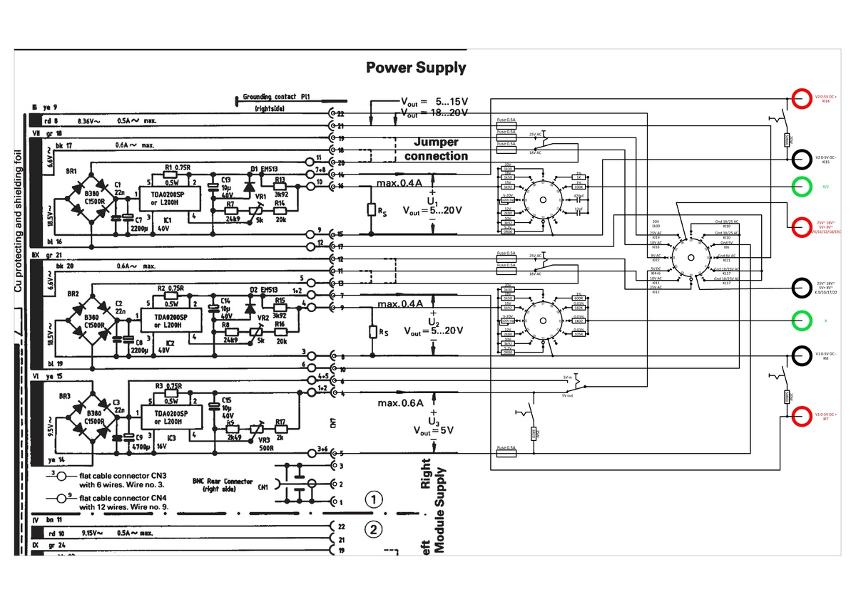
Schaltplan eines mehrstufigen Netzteils
max. 0.5A~ max. VR 17 0.6A~ max. Cu protecting and shielding foil 18.5V~ BR1 C1000 C1 TD4020SP or L200H K1 bl 16 BX gr 21 0.6A~ max. BR2 C1000 C2 TD4020SP or L200H K2 bl 19 18.5V~ 19 20 21 22 23 24 25 26 27 28 29 30 31 32 33 34 35 36 37 38 39 40 41 42 43 44 45 46 47 48 49 50 51 52 53 54 55 56 57 58 59 60 61 62 63 64 65 66 67 68 69 70 71 72 73 74 75 76 77 78 79 80 81 82 83 84 85 86 87 88 89 90 91 92 93 94 95 96 97 98 99 100 101 102 103 104 105 106 107 108 109 110 111 112 113 114 115 1
in „WOMA HAMEG HM800X-Test Unit“ · Projekte & Code · · Schaltpläne
-
PDF
usb_uart_board_sch_v100.pdf
CN1 1 VCCUSB FP1 VCCIO 20 VCCIO 1 RX-MCU o VBD+ 3 USBDP C1FERRITE C2 USBDM 16 USBDM RTS# 3 RTS-MCU l GND 5 100nF 100nF USBDP 15 USBDP DTR# 91 CTS-MCU TX-MCU CN21 e USB MINIB 19 NC DCD# 60 CTS-MCU 3 v J6 VCC 3V3OUT VCCIO 27 OSCIT# CBUS1 22 VCCIO 6 e 2 VCCIO E1 28 OSCO CBUS3 12 M1X6 3 3V3OUT 100nF 10uF 3V3OUT17 3V3OUT A G G G T CBUS4 D M1X3 2 7 1 2 2 a k i n o t k l E o r k USB UART Board Schematic v100 Page 1/1 i M
in „USB to UART problem“ · Mikrocontroller und Digitale Elektronik ·
-
PDF
MAX639-MAX653.pdf
3.43 V MAX653, V+ = 4.0V to 11.5V, 0mA < OUT < 100mA 2.88 3.00 3.12 Dropout Voltage IOUT = 100mA, L = 100µH 0.5 V IOUT = 100mA, L = 100µH 91 MAX639 IOUT = 25mA, L = 470µH 94 IOUT = 100mA, L = 100µH 87 Efficiency MAX640 % IOUT = 25mA, L = 470µH 91 IOUT = 100mA, L = 100µH 85 MAX653 IOUT = 25mA, L = 470µH
in „Spannung am Ausgang eines Converters anlegen“ · Mikrocontroller und Digitale Elektronik ·
-
PDF
KLS2_Schaltungen.pdf
1 15R 1 R 1 R 0 1 %k02 B 0 1 %k02 D 1 R 1 R % 8 02R % 0 05R k R k R 1 1 %k02 B 1 1 %k02 D R R % 7 91R % 9 94R k R k R 0 1 1 %k02 B 1 1 %k02 D 81R R 84R R 1 6 1 3 k R k R 2 2 DNG DNG B E Z S B L - U D 2 + 1 BSU 6 P X U 4 3 2 1 P D N C 1 0 G C 1 D + N r 1 0 G e C 0 D l 1 N g 0 9 7 8 7 5 6 5 G e 5 2 4
in „Matching Transistoren“ · Analoge Elektronik und Schaltungstechnik ·
-
PDF
FM_AM-Tuner_TEA5757HL_5759HL_1.pdf
BB112(12) TUNE 47 k 2 AM AM AM AM AGC AM V/I (5) E FRONT-END OSCILLATOR MIXER IF DETECTOR CONVERTER L5 A 22 nF L1 18 5 pF 7 7 (1) 44 45 39 48 9 23 11 12 4 5 (2) (3) 10 F 10 nF 220 nF 7 L2 L3 H (4) L 18 pF 330 pF ; L4 T P 18 pF BB112(12) 470 nF MHB642 r d E o VSTAB(A) w VSTAB(B) TUNE V A u 470 pF 47 k
in „Autoradio selber bauen.“ · Mikrocontroller und Digitale Elektronik ·
-
PDF
isco_3700.pdf
Procedure VOLUME? [YES,NO] Key Times Display #90 ENTERSTARTTIME? No Yes [YES,NO] Time Flow Display #91 Display #92 TAKEFIRSTSAMPLEAT STARTFLOWCOUNTAT HH:MM DD-MMM HH:MM DD-MMM . . . STANDBY . . . 9:54:22 12-SEP-91 31 3700 Standard and 3700 Compact Sampler Note: When entering the sample volume, keep in
in „Reparatur Motorsteuerung, Probennehmer“ · Mikrocontroller und Digitale Elektronik ·
-
PDF
BE-412-B-MONITOR-HEIDENHAIN-MANUAL.pdf
IC-Pl) Index (Software-Stand) RECHNER-Platine REGELKREIS-Platine HEIDENHAIN SERVICEAMLEIVDIiG VW 35lKEi5 DFLJOHANNES HEIDENHAIN GmbH Blatt 91 0-8225 Traunreut.Tel.(08669)31-0 Kundendienst 17- Maschinen-Parameter Die Haschinen-Parameter sind in nachfolgender Liste fdr alle Software-Varianten aufgeführt
in „CRT Monitor gegen VGA Monitor tauschen“ · Analoge Elektronik und Schaltungstechnik ·
-
PDF
HFD2.pdf
P\j`jkXeZ\BccfnXYc\ MldY\i /TED0 / 76-0 TfckX^\ L\Z_Xe`ZXc c`]\ 7 o 76>NOQ /TED0 /TED0 /TED0 6693L 9 8496 649 :; < 05.<.0>2<6=>60= 66;3L ; 94=; 64; 78; 76 66<3L < :4;6 64< 7>6 78 Je`k`Xc `ejlcXk`fe i\j`jkXeZ\ 7666L /Xk ;66TED0 7Zf`c@ 7;66TBD 7d`e4 66
in „# Was ist das für ein Relais HFD2/005-M-D(555) ?“ · Analoge Elektronik und Schaltungstechnik ·
-
PDF
GZH2350.pdf
DEL- TRP HC- R 2 P V51+ 1 2 1 0 W 2 1 2P S HC-L W C 1 2 U F S 2 L P R 2 F L 4 F L 5 L 0 R N T D 2 7 3 7 L W R R E 5 K 1 0 5 5 5 1 7 P i P i 1 0 I J - + 2 0 I 0 P P R 1 N R 1 J 3 GD 3 N DG 4 K 4 K 1 1 2 1 R R G G 022 K05B D M481 022 K05B D M481 341R
in „Endstufe KFZ will nicht mehr“ · Analoge Elektronik und Schaltungstechnik ·
-
PDF
1N4150.pdf
p =1ms FSM 4 A Forward current F 600 mA Average forward current VR=0 FAV 300 mA Power dissipation l=4mm, TL=45°C P V 440 mW l=4mm, TLx25°C P V 500 mW Junction temperature T 175 °C j Storage temperature range Tstg –65...+175 °C Maximum Thermal Resistance Tj= 25_C Parameter Test Conditions Symbol Value Unit Junction ambient l=4mm, T Lconstant RthJA 350 K/W Document Number 85522 www.vishay.de FaxBack +1-408-970-5600 Rev. 2, 01-Apr-99 1 (3) 1N4150 Vishay Telefunken Electrical Characteristics Tj= 25_C Parameter Test Conditions
in „AVR Port schützen vor höherer Spannung“ · Analoge Elektronik und Schaltungstechnik ·
-
PDF
D351049D.pdf
light industry level, criteriaA MTBF 1200.6K hrs min. MIL-HDBK-217F (25J) OTHERS DIMENSION 140*30*22(L*W*H) PACKING 0.175Kg; 70pcs/13.3Kgs/0.71CUFT 1. All parameters NOT specially mentioned are measured at 230VAC input, rated loadof ambient temperature. NOTE 2. Ripple & noise are measured at 20MHz of
in „LEDS hinter Konstantstromquelle dimmen“ · Mikrocontroller und Digitale Elektronik ·
-
PDF
TypeManager_Print_Test_Sheet.pdf
62 ? 63 3 0 1 2 3 4 5 6 7 8 9 : ; < = > ? @ 64 A 65 B 66 C 67D 68 E 69 F 70 G 71H 72 I 73 J 74 K 75 L 76M 77 N 78 O 79 4 @ A B C D E F G H I J K L M N O P 80 Q 81 R 82 S 83T 84 U 85 V 86 W 87X 88 Y 89 Z 90 [ 91 \ 92] 93 ^ 94 _ 95 5 P Q R S T U V W X Y Z [ \ ] ^ _ ` 96 a 97 b 98 c 99d 100 e 101 f 102 g 103h 104 i 105 j 106 k 107 l 108 m 109 n 110 o 111 6 ` a b c d e f g h i j k l m n o p 112 q 113 r 114 s 115t 116 u 117 v 118 w 119x 120 y 121 z 122 { 123 | 124 } 125 ~ 126 127 7 p q r s t u v w x y z { | } ~ € 128 129 ‚ 130 ƒ 131
-
PDF
Dot5x7.pdf
62 ? 63 3 0 1 2 3 4 5 6 7 8 9 : ; < = > ? @ 64 A 65 B 66 C 67D 68 E 69 F 70 G 71H 72 I 73 J 74 K 75 L 76M 77 N 78 O 79 4 @ A B C D E F G H I J K L M N O P 80 Q 81 R 82 S 83T 84 U 85 V 86 W 87X 88 Y 89 Z 90 [ 91 \ 92] 93 ^ 94 _ 95 5 P Q R S T U V W X Y Z [ \ ] ^ _ ` 96 a 97 b 98 c 99d 100 e 101 f 102 g 103h 104 i 105 j 106 k 107 l 108 m 109 n 110 o 111 6 ` a b c d e f g h i j k l m n o p 112 q 113 r 114 s 115t 116 u 117 v 118 w 119x 120 y 121 z 122 { 123 | 124 } 125 ~ 126 127 7 p q r s t u v w x y z { | } ~ € 128 129 ‚ 130 ƒ 131
in „Suche Font mit alphanumerischen 5x7/5x8 LCD Zeichen“ · PC Hard- und Software ·
-
PDF
schraube.pdf
Kreise, auf 3 welche man die aus dem 'I Grundrisse entnommenen Bo genlangen, von einer Geraden 5 6 l' 7' aus auftragt, wie dies die Abbildungen deutlich er- kennen lassen. Durch Verbin dung der 80 erhaltenen Punkte erhalt man die Abwicklung, wie sie Abb. 307 zeigt. IV. SchraubenfUiche Eine ziemlich
in „Archimedische Schraube/Brunnenbohrer selbst bauen - wie?“ · Mechanik, Gehäuse, Werkzeug ·
-
PDF
PFC_FBC.pdf
Aufbereitung der Netzspannung für die Messung N _ T _ 3 3 + 3 IC16C 0 T LM324(SO14) 1 A D B L_SENSE 10 D18 8 R20 30k L_POLARITY 9 N BAT43 N R21 10k N L O T _ 3. 01 3 N + 91 _ R T IC16B 4 _ N LM324(SO14) T V 9 A 1 5 D B + L_SENSE R17 10k 7 L_VALUE R R16 20k 6 k IC16A 4 2 4 1 3 LM324(SO14) D k
in „PFC + Vollbrücken-Gegentaktwandler“ · Analoge Elektronik und Schaltungstechnik ·
-
PDF
SpartanXL.pdf
P128 - GND - - J3 P27 - I/O P27 P18 J4 P28 152 I/O P3 P90 A6 P129 44 I/O - P19 K1 P29 155 I/O P4 P91 B6 P130 47 I/O - P92 C6 P131 50 I/O - - K2 P30 158 I/O - - K3 P31 161 I/O - P93 D6 P132 53 I/O P5 P94 A5 P133 56 I/O P28 P20 L1 P32 164 I/O, P29 P21 L2 P33 167 I/O P6 P95 B5 P134 59 SGCK2 (1) I/O - -
in „Logic Analyzer bauen“ · Mikrocontroller und Digitale Elektronik ·
-
PDF
XCS20-3VQ100C.pdf
I/O - - L5 P46 193(3) I/O P62 P62 G12 P89 298(3) I/O - - M5 P47 196(3) (3) VCC P63 P63 G13 P90 - I/O P38 P31 N5 P48 199 GND P64 P64 G11 P91 - I/O P39 P32 K6 P49 202(3) I/O (D3 ) P65 P65 G10 P92 301(3) I/O - P33
in „[V] Spartan FPGA“ · Markt ·
-
PDF
mbr1090c.pdf
0.185 (4.70) • Plastic package has Underwriters Laboratory Flammability Classification 94V-0 0.154 (3.91) 0.175 (4.44) 0.370 (9.40) 0.055 (1.39)• Dual rectifier construction, positive center tap 0.360 (9.14) 0.148 (3.74) 0.045 (1.14) 0.113 (2.87) • Metal silicon junction, majority carrier conduction 0.103
in „Dual High-Voltage Schottky Rectifiers 10A“ · Mikrocontroller und Digitale Elektronik ·
-
PDF
IL74.pdf
temperature current and temperature 1.5 1.5 b Normalized to: Normalized to: R IF =10 mA e Vce = 10V T l 70°C 50°C C1.0 Vcb = 9.3 V a 1.0 Ib = 20 A e Ta = 25°C r H 25°C Ta = 25°C l o d m - t o t r -20°C N0.5 25°C s t.5 - E S c 50°C F Vce = 0.4V T 70°C N C0.0 0.0 N .1 1 10 100 1 10 100 1000 IF - LED Current
in „Hilfe für Schaltung gesucht“ · Mikrocontroller und Digitale Elektronik ·
-
PDF
IL74_ILD74_ILQ74_SIE.pdf
temperature current and temperature 1.5 1.5 b Normalized to: Normalized to: R IF =10 mA e Vce = 10V T l 70°C 50°C C1.0 Vcb = 9.3 V a 1.0 Ib = 20 A e Ta = 25°C r H 25°C Ta = 25°C l o d m - t o t r -20°C N0.5 25°C s t.5 - E S c 50°C F Vce = 0.4V T 70°C N C0.0 0.0 N .1 1 10 100 1 10 100 1000 IF - LED Current
in „Eingänge über Optokoppler abfragen“ · Mikrocontroller und Digitale Elektronik ·
-
PDF
744771168_Data-DE.pdf
properties test conditions Wert / value Einheit / unit tol. [mm] 5,4 Induktivität / 1 kHz / 0,25V L 68,00 µH ±20% Inductance DC-Widerstand / @ 20°C R 0,096 typ. 2,9 DC-resistance DC typ. Ω DC-Widerstand / DC-resistance @ 20°C R DC max. 0,120 Ω max. 7,0 12,8 Nennstrom / ∆T=40 K IDC 1,91 A max. Rated current Sättigungsstrom / |∆L/L|<10% I 2,19 A typ. 2,9 Saturation current sat Eigenres.-Frequenz / Self-res.-freency SRF 6,00 MHz min. D Prüfgeräte / test equipment : E Testbedingungen / test conditions : HP 4274 A für/for L und/
in „Probleme mit dem LM3404“ · Mikrocontroller und Digitale Elektronik ·
-
PDF
schematic_full.pdf
0 V 1 1µ 3 6 7 C R2 6n8 2 VIN- RG$2 8 100n 4 k GND JP1 N R7 3 VIN+ V+ 7 3 2 C22 LD1117AS33TR MEGA8L B 22k 6 VOUT V- 4 LMV321M7 2 n IN OUT IC4 r 1-227161-022k C29 2 0 29 PC6(/RESET) PC0(ADC0) 23DRDY u non-inv. INA155 R 1 C14 ADJ C18 PC1(ADC1) 24CS1 G 680p IC3 21 GND PC2(ADC2) 25START 100n 10µ 20 AREF
in „EEG mit AVR und ADS1194: Kritik und Anregungen“ · Analoge Elektronik und Schaltungstechnik ·
-
PDF
BettyHHU.pdf
AMB_A11 ; DQ9 32 R94 2M AMB_D7 ICT12 RST 0 AMB_A12 6 S DQ10 34 6 A10 H AMB_D10 ICT11 12 D7 1 5 A11 1 7 L 6 S DQ10 34 AMB_D6 13 5 6 3 ; 3 DQ11 36 AMB_D11 AMB_A12 5 A11 1 7 L ICT10 D6 R21 R20 R19 AMB_A13 4 A12 ; D D 3 ; 3 DQ11 36 AMB_D11 AMB_D5 14 D5 1MR 1MR 1MR C N D DQ12 39 AMB_D12 AMB_A13 4 A12 ; D D AMB_D4
in „Innenleben von Betty TV“ · Mikrocontroller und Digitale Elektronik ·
-
PDF
Valvo_Brief_FD11_260178.pdf
Induktivität1nbis 7 sind mit Valvo-Spulenbauteilen im Gehäuse für Einzelkreis 3122 990 94130 aufgebaut: L4 500 Wdgn. 0,09 CuL Anzapfung bei 165 Wdgn. L1 7 Wdgn. 0,2 CuL vom kalten Ende auf Liliput-Spulenkörper 4312 021 29660 auf Miniput-Spulenkörper 4312 021 29670 mit Rahmenkern 3122 104 91480 mit Rahmenkern
in „(V) Valvo FD11“ · Markt ·
-
PDF
74HCT4543_1.pdf
L H H 5 H L L L H H L H L H H H H H 6 H L L L H H H H H H L L L L 7 H L L H L L L H H H H H H H 8 H L L H L L H H H H H L H H 9 H L L H L H L L L L L L L L blank H L L H L H H L L L L L L L blank H L L H H L L L L L L L L L blank H L L H H L H L L L L L L L blank H L L H H H L L L L L L L L blank H L L H H H H L L L L L L L blank L L L X X X X (1) (1) as as H as above inverse of above above above Notes 1
in „Welcher Treiber zu 7 Segment LED mit Common Anode“ · Mikrocontroller und Digitale Elektronik ·
-
PDF
21425b.pdf
dissipation in the device. TRUTH TABLE Part No. TC4467 NAND TC4468 AND TC4469 AND/INV Inputs A H H L L H H L L H H L L Inputs B H L H L H L H L H L H L Outputs TC446X L H H H H L L L L H L L Legend: H = High L = Low DS21425B-page 4 © 2002 Microchip Technology Inc. TC4467/TC4468/TC4469 2.0 TYPICAL PERFORMANCE
in „Problem mit dem TC4469“ · Mikrocontroller und Digitale Elektronik ·
-
PDF
74HC_HCT138.pdf
demultiplexer; inverting 6. Functional description Table 3. Function table H = HIGH voltage level; L = LOW voltage level; X = don’t care. Control Input Output E1 E2 E3 A2 A1 A0 Y7 Y6 Y5 Y4 Y3 Y2 Y1 Y0 H X X X X X H H H H H H H H X H X X X L L L H L L L H H H H H H H L L L H H H H H H H L H L H L H H H H H L H H L H H H H H H L H H H H L L H H H L H H H H H L H H H L H H H H H H H L H L H H H H H H H H H L H H H H H H H 7. Limiting values Table 4. Limiting values In accordance with the Absolute Maximum Rating
-
PDF
opa2134.pdf
Figure 4. Headroom – Total Harmonic Distortion + Noise vs Output Amplitude 0.01 1k ) 2nd Harmonic l 3rd Harmonic OP176+ n z Resistor e 0.001 H 100 a / n 600W n u R L= ( f 0.0001 i 10 o o OPA134+ ( W e Resistor d =2k a i 0.00001 R L l p V 1 m Resistor Noise A V (total) = Ö(iR ) + + 4kTR VO= 1Vrms Only
in „Unerwünschtes Rauschen bei Allpassfiltern“ · Analoge Elektronik und Schaltungstechnik ·
-
PDF
EW50793FLWP.pdf
θy- = 1° Ta=-20°C 4500 5850 t r ( rise ) Ta=25°C 300 390 msec 1 θx = ° RESPONSE TIME Ta=70°C 70 91 Ta=-20°C 3000 3900 θy- = 1° t f ( fall ) Ta=25°C 190 247 msec 1 θx = ° Ta=70°C 90 117 THE BRIGHTNESS OF 2 MODULE L 14 16 cd / m 1,2 VLED-VSS=5.0V THE UNIFORMITY OF 30 % 2,3 MODULE NOTE ( 1
in „anschluss Potentiometer“ · Mikrocontroller und Digitale Elektronik ·
-
PDF
Pierce.pdf
Streukapazitäten und Gatterstreuungen an: von typisch 10ppm/pF bei C = 30pF [Grundwelle] auf über 50ppm/pF bei L C ≤10pF). Der durch C transformierte Lastresonanzwiderstand R steigt L L L ebenfalls für kleine C -WerteLsteil auf ein Vielfaches des Resonanzwiderstandes R rn. Als Faustregel gilt: . C L 2C 0 d.h. C ≥L8 ... 10 pF •C nicxi zu groß Mit höherem C fällt xie Schleifenverstärkung stark ab, so daß das Anschwingen nicht mehr gewährleistet ist. •Verhältnis C : C x1 x2 Die Werte von C ’und C ’sollten etwa gleich
in „Hilfe: Takt Mission (Philips) CD-Player fällt aus“ · Analoge Elektronik und Schaltungstechnik ·
-
PDF
avr450.pdf
AVR450 Appendix 1: Schematic Figure 16. Block diagram of main blocks B o 2 w P s U p S y H S i h s L D a d A S S S S l WW WW g A T T T T L L L L A A e N N H H H H E E E E R C C V r D D 3 2 1 0 3 2 1 0 F C C N n e B A B A 2 i 2 9 G A A V V 1 y G A S S S S L L L L A A V V 1 _ S N G R C N 0 5 N G WW WW
-
PDF
27512EP_EDA.pdf
CALL L1CE1 73 jmp Z,L1939 74 SUB 030 75 mov [si-002],A 76 mov HL,01934 77 mov B,6 78 L1A02 DEC A 79 jmp Z,L1A0A 80 INC HL 81 DJNZ L1A02 82 jmp L19DA 83 ; 84 L1A0A mov L,[HL] 85 mov B,007 86 L1A0D mov A,[HL] 87 INC HL 88 call 10H 27512EP.EDA Page 2 89 DJNZ L1A0D 90 call PRINT 91 db 00E 92 db "1508EPROM-Adress" 93 db "en [Ohne Eingabe" 94 db " gesamtes Eprom]" 95 db " +080 96 CALL L1CE1 97 jmp Z,L19DA 98 L1A4A call PRINT 99 db 00E 100 db "1712Anfang :" 101
in „EDA-Dateien bearbeiten“ · Mikrocontroller und Digitale Elektronik ·
-
PDF
CFAG12864BTFHV_v3.0.pdf
NOTES: 1. Based on Vss=0V 2. Applies to input terminals and I/O terminals at high impedance. (Except V0L(R), V1L(R), V4L(R) and V5L(R)) 3. Applies to V0L(R), V1L(R), V4L(R) and V5L(R). 4. Voltage level: VDD≧V0L=V0R≧V1L=V1R≧V4L=V4R≧V5L=V5R≧VEE. ELECTRICAL CHARACTERISTICS DC CHARACTERISTICS (V =+5.0V, VDD
in „avr asm LCD Problem“ · Mikrocontroller und Digitale Elektronik ·
-
PDF
sharp_r733.pdf
sont entrés dans INT1. 22 R83 SORTIE Borneinutilisée. 23 R90 ENTREE Entrer le signal qui communique l’information d’ouverture/fermeture de la porte au circuit LSI. Porte fermée, signal de niveau “L” (0 V). Porte ouverte, signal de niveau “H” (+5 V). 24-25 R91-R92 SORTIE Borne inutilisée. 26 VDD ENTREE
in „Fragen zu einem Trafo einer Sharp R733(W) Mikrowelle“ · Analoge Elektronik und Schaltungstechnik ·
-
 Bild
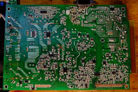
Foto einer Leiterplatte mit Bestückungsdruck
R71, R72, R73, R74, R75, R76, R77, R78, R79, R80, R81, R82, R83, R84, R85, R86, R87, R88, R89, R90, R91, R92, R93, R94, R95, R96, R97, R98, R99, R100, C1 bis C100, L1 bis L10, U1 bis U10, D1 bis D10, 2026-08-09 12:31:39
in „Dell Netzteil, Dell F685EF-00 , kein Piep mehr“ · PC Hard- und Software · · Platinenfotos
-
 Bild
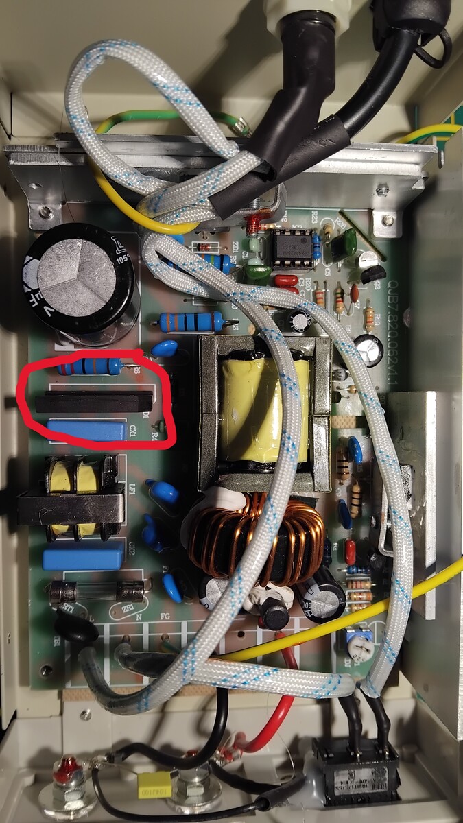
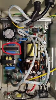
Innenansicht eines Schaltnetzteils mit Bauteilen
105, QUB7A206211, L1, L2, N, FG, R1, R2, R3, R4, R5, R6, R7, R8, R9, R10, R11, R12, R13, R14, R15, R16, R17, R18, R19, R20, R21, R22, R23, R24, R25, R26, R27, R28, R29, R30, R31, R32, R33, R34, R35, R36, R37, R38, R39,
in „Albrecht SW57 Gerät geht nicht mehr an“ · Platinen · · Platinenfotos
-
 Bild
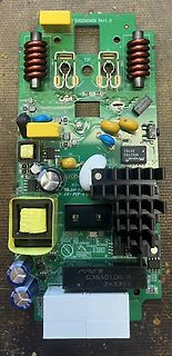
Foto einer Leiterplatte mit Leistungselektronik
2062500456 Rev1.0 L001 L002 TOP C5 C6 C7 C8 C9 C10 C11 C12 C13 C14 C15 C16 C17 C18 C19 C20 C21 C22 C23 C24 C25 C26 C27 C28 C29 C30 C31 C32 C33 C34 C35 C36 C37 C38 C39 C40 C41 C42 C43 C44 C45 C46 C47 C48 C49 C50 C51 C52
in „Ethernet über 2adrige Telefonleitung. Idee: Billige Powerline Adapter für z.B. 24V umbauen. Mögli“ · Mikrocontroller und Digitale Elektronik · · Platinenfotos
-
PDF
Nixie.pdf
4 5 0 3 2 1 + 1 1 1 1 DNG 2 3 7 6 1 1 1 1 N 1 1 2 2 3 3 4 4 D G Q Q Q Q Q Q Q Q 5 P1CI 1 C 1 2 3 4 L L C V D D D D C C 4 1 7 5 4 5 1 1 91 +
in „Steuerung 150V Nixie IN-14: mind. 40 Pins“ · Analoge Elektronik und Schaltungstechnik ·
-
PDF
21709c_EEPROM.pdf
0.18 0.25 Overall Width E .228 .237 .244 5.79 6.02 6.20 Molded Package Width E1 .146 .154 .157 3.71 3.91 3.99 Overall Length D .189 .193 .197 4.80 4.90 5.00 Chamfer Distance h .010 .015 .020 0.25 0.38 0.51 Foot Length L .019 .025 .030 0.48 0.62 0.76 φ Foot Angle 0 4 8 0 4 8 Lead Thickness c .008 .009 .010
in „EEPROM mit Infineon XC2200 ueber IIC benutzten“ · Mikrocontroller und Digitale Elektronik ·
-
PDF
21709c.pdf
0.18 0.25 Overall Width E .228 .237 .244 5.79 6.02 6.20 Molded Package Width E1 .146 .154 .157 3.71 3.91 3.99 Overall Length D .189 .193 .197 4.80 4.90 5.00 Chamfer Distance h .010 .015 .020 0.25 0.38 0.51 Foot Length L .019 .025 .030 0.48 0.62 0.76 φ Foot Angle 0 4 8 0 4 8 Lead Thickness c .008 .009 .010
in „24LC02B mit (scheinbar) seltsamer Adressierung“ · Mikrocontroller und Digitale Elektronik ·
-
PDF
HD66766-10.pdf
GND GND GND GND GND GND GND RESET2* ITO ITO ITO Slit Figure 3 ITO Connection Pattern (Recommended) 91 HD66766 Rev. 1.0 / 30 November 2001 Maintenance history report: ( ex. P53 = page53 / L3 = line 3 / - = blank ) Rev. 0.1 First edition 2001.06.25 Rev. 0.2 P16 4096 color controle bit (SPR) added on the
in „The Siemens S65 132x176, 65536 color display with AVR“ · Projekte & Code ·
-
PDF
KEI_181_Service.pdf
R-RR-392K R-112 lnR.RK, .l%, I/RW, MTF C6 91/c5 "LE CMP1,lO R-176-108.8K R-113 IM, .I%, l,t?W. MTF cc, 92/C!' ",.F MFFI,R R-176-,,+ R-114 402K. 1%. IIRW, Fixed 0s 93/c5 "LE MFFIIR R-RR-4O?K R-115 lnK, 10%. 1/4W, Comp 82 94/C2
-
Datei
Bauteilliste.txt
holes (48.26 33.02) R0 H2 M3 3,2-PAD holes (5.08 33.02) R0 IC1 LM317 317TL v-reg (16.51 33.02) R90 IC2 L272M DIL08 linear (10.16 21.59) R0 IC3 L272M DIL08 linear (43.18 21.59) R0 JP1 JP1 jumper (26.67 39.37) R270 L1 10uH BC12 inductors (40.64 39.37) R0 LED1 grün CHIPLED_1206 led (20.32 39.37) MR90 R1 10R
in „Puffer für DCC-Dekoder mit Superkondensatoren“ · Projekte & Code ·
-
PDF
MischEndstufe.pdf
2 C3 6 6 R10 X2 1k 19,8V 200/35 R11 2k2 C4 16,4V 200/35 X1 X3 R58 R57 470k 16k 3 14,8V -18,3V V2 6L6GC BC107A C33 R82 132V Vorst. NC31 6 0 R67 68k 1 0,1/630 R90 4 T10 5/35 R 7 8 5 e i X4 5/35 4 16k 470pF/400V V1A C C39 12k c t 1,5V 0,82V E 8 B C30 e R70 2 2 , W 2 7 - V 32µF-550/600 f R60 R59 C35 1
in „Wert des Koppelkondensator veränderbar?“ · Analoge Elektronik und Schaltungstechnik ·
-
PDF
VDO-Druckgeber-Pressure_Sensors.pdf
( äA2 x A5( /// 2,5( A2 l 0, 360-081-029-085C ( äA4 x A5( /// 2,5( A2 l 0, 360-081-029-026C/K ( äA4 x A5( /// 2(5( A2 0, 360-081-029-065C ( äA4 x A5( /// 2,5( A2 Ø 0, 360-081-048-003C ( äAR x A5( l /// 2,5( A2 l 0, 360-081-029
in „Druckgeber auswerten“ · Mikrocontroller und Digitale Elektronik ·