-
PDF
LCD-Controller_NT3881.pdf
= -0.25mA DB0 - DB7 (TTL) V OL1 "L" Level Output Voltage (1) - - 0.4 V IOL = 1.2mA V OH2 "H" Level Output Voltage (2) 0.9 VDD - - V IOH = -0.04mA CL1, CL2, M, D (CMOS) V OL2 "L" Level Output Voltage (2) - - 0.1 VDD V IOL = 0.04mA V COM
in „Frage zu GCC Tutorial LCD“ · Mikrocontroller und Digitale Elektronik ·
-
PDF
nt3881.pdf
= -0.25mA DB0 - DB7 (TTL) V OL1 "L" Level Output Voltage (1) - - 0.4 V IOL = 1.2mA V OH2 "H" Level Output Voltage (2) 0.9 VDD - - V IOH = -0.04mA CL1, CL2, M, D (CMOS) V OL2 "L" Level Output Voltage (2) - - 0.1 VDD V IOL = 0.04mA V COM
in „LCD mit NT3881D“ · Mikrocontroller und Digitale Elektronik ·
-
PDF
datasheet-Novatec_display_controller.pdf
= -0.25mA DB0 - DB7 (TTL) V OL1 "L" Level Output Voltage (1) - - 0.4 V IOL = 1.2mA V OH2 "H" Level Output Voltage (2) 0.9 VDD - - V IOH = -0.04mA CL1, CL2, M, D (CMOS) V OL2 "L" Level Output Voltage (2) - - 0.1 VDD V IOL = 0.04mA V COM
in „mal wieder ein LCD am Atmega8“ · Mikrocontroller und Digitale Elektronik ·
-
Datei
mein_F205_board.h
) // 34 PIN ( B, 14, MO_RTS_L, OUT | HI ) // 35 PIN ( B, 15, MO_CTS_L, IN ) // 36 PIN ( C, 6, MO_TXD, AF_USART6 ) // 37 PIN ( C, 7, MO_RXD, AF_USART6 ) // 38 PIN ( C, 8, U4_RTS_H, OUT | LO ) // 39 PIN ( C, 9, 4KHZ, AF_TIM3 | OD |
in „STM32 gpio_init() -- was haltet ihr von dieser Version?“ · Mikrocontroller und Digitale Elektronik ·
-
PDF
fn8271_1_.pdf
5.0 12 4.5 ) 4.0 5.0V ( 10 N ) 3.5 3.3V E 8 5.0V ( 3.0 R 3.3V S 2.5 1.5V 2.5V U 6 2.5V S 0.8V D 1.5V L 2.0 A 1.5 L 4 0.8V X 1.0 A 2 0.5 M 0.0 0 60 70 80 90 100 110 0 2 4 6 8 10 LOAD CURRENT (A) AMBIENT TEMPERATURE (°C) FIGURE 39. POWER LOSS vs LOAD CURRENT (12V IN) 0 LFM FOR FIGURE 40. DERATING CURVE
in „Spannungsregler 5V 10A“ · Analoge Elektronik und Schaltungstechnik ·
-
Datei
display_lib.c
0; i < ((x2-x1)*(y2-y1)); i++) { LCD_Write_DATA(VH, VL); } SET_CS; } void vline(int x, int y, int l, char VH, char VL) { int i; CLR_CS; set_Cursor(x,y,x,y+l); for(i=0;i<l;i++) { LCD_Write_DATA(VH,VL); } SET_CS; } void hline(int x, int y, int l, char VH, char VL) { int i; CLR_CS; set_Cursor(x,y,x+l,y); for(i=0;i<l+1;i++) { LCD_Write_DATA(VH,VL); } SET_CS; } void pixel(int x, int y, char VH, char VL) { CLR_CS; set_Cursor(x,y,x,y); LCD_Write_DATA(VH,VL); SET_CS; } void drawallchars() { int tempx = 0; int tempy =
-
PDF
SCH_ESP32-Ethernet-Kit_A_V1.2_20200528.pdf
place these caps close to VCORE/VCCIO VDD1V8 VDD1V8 VDD1V8 VDD33 VDD33 VDD33 VDD1V8 VDD33 C28 C29 C30 L1 1Kohm@100MHz L2 1Kohm@100MHz 0.1uF/16V(10%) 0.1uF/16V(10%) 0.1uF/16V(10%) R73 R74 R75 C31 C32 C33 C34 GND GND GND 4.7uF/6.3V(10%) 4.7uF/6.3V(10%) 0.1uF/16V(10%) 0.1uF/16V(10%) 2 7 4 0 1 2 6 D 10K(5%
in „Arduino Library für Netzwerkchip W5500?“ · Mikrocontroller und Digitale Elektronik ·
-
Datei
eclipse_log.txt
:37:51.366 !MESSAGE Suspend operation timeout. !ENTRY org.eclipse.cdt.dsf 4 10005 2017-01-18 13:37:53.399 !MESSAGE Request for monitor: 'RequestMonitor (org.eclipse.cdt.dsf.concurrent.RequestMonitor@d12c421): Status ERROR: org.eclipse.cdt.dsf.gdb code=10004 Suspend operation timeout. null' resulted in an error. !SUBENTRY 1 org.eclipse.cdt.dsf.gdb 4 10004 2017-01-18 13:37:53.399 !MESSAGE Suspend operation timeout. !ENTRY org.eclipse.cdt.dsf 4 -1 2017-01-18 13:37:55.463 !MESSAGE Invocation exception when calling a service event handler method !STACK 0 java.lang.reflect.InvocationTargetException
in „Problem mit Breakpoints (Eclipse + JLink)“ · Mikrocontroller und Digitale Elektronik ·
-
PDF
02-ETEK-Modular-Distribution-Electric-2024.pdf
EN61643-11 Technical Data No.of poles 1P 2P 3P 4P 1P+NPE 3P+NPE Network systems TN-S, TN-C, TT(only L-N) TN-S TN-C TN-S TT, TN-S Mode of protection L-PE, N-PE(onlyTN-S), L-PE, N-PE L-PEN L-PE, N-PE L-N, N-PE L-PEN, L-N Protective elements High Energy MOV High Energy MOV and GDT Maximum continuous operating
in „Balkonkraftwerk an alter E-Installation“ · Haus & Smart Home ·
-
PDF
littelfuse-PTC-Rline-Catalog.pdf
B B B D D D D D C D D D D D D D C C F C C F F C CLtoL F Cto C C F Cto C C C to C C LC LCtCL F LF L C LC LCtCL LFLCF L LC CLtoL CL L L tCL tLCtoL C CL L LtoLCtoLtoL C C L C to L L L L L L L L L Figure R9 Figure R10 Figure R11 A E A A E E A A E E A A A E
in „Batteriehalter mit unbekannten Bauteil“ · Analoge Elektronik und Schaltungstechnik ·
-
PDF
Schematic_Sheets.PDF
1 2 3 4 +24V_L1 +24V_L8 +24V_L15 2 2 2 R3 Q3 R1 1 D Q1 R2 1 DQ2 1 G DIRL4905 R4 G S IRL4905 R5 G SIRL4905 A PIN_22 R6 4.7k S PIN_29 Q44.7k PIN_36 Q5 4.7k A Q6 3.9k BC547 R7 3 3.9k BC547 R8 3 3.9k BC547 R9 3 +24V_L2
in „LED Strips an Treppe mit PWM der Reihe nach Ein/Aus“ · Analoge Elektronik und Schaltungstechnik ·
-
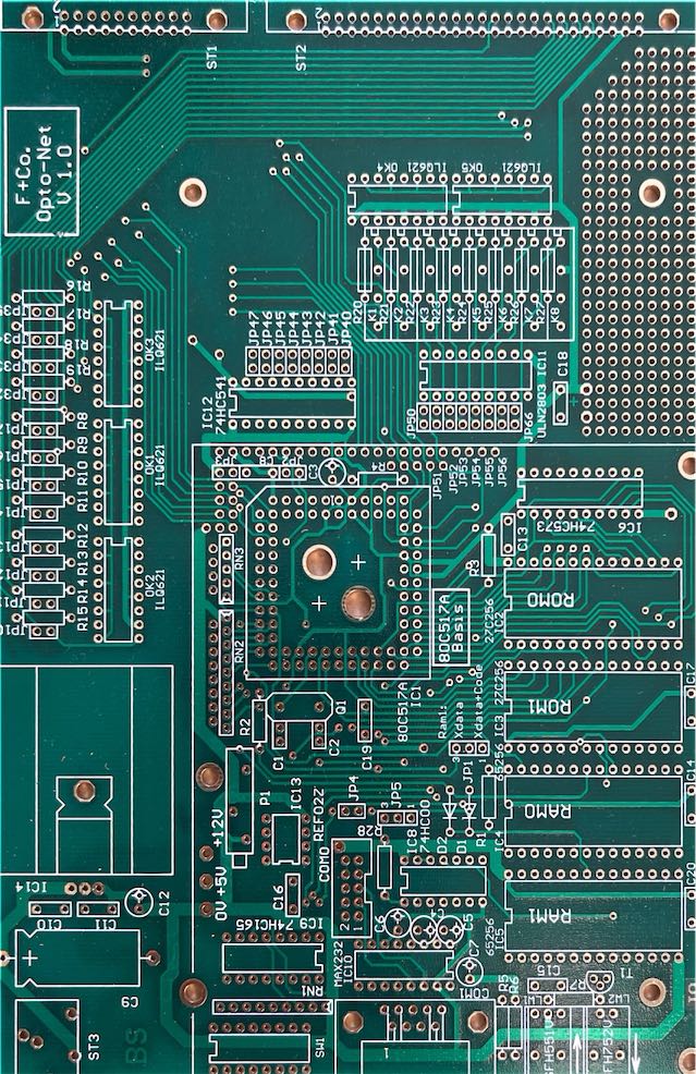
 Bild
Grüne Leiterplatte mit Bestückungsdruck
F+Co. Opto-Net V.1.0 ST1 ST2 L621 OK3 L621 OK4 L621 OK5 L621 OK6 IC12 74HC541 IC13 IC18 IC1 74HC541 IC6 74HC573 ROMO ROM1 RAMO RAMI IC14 IC13 IC10 IC11 IC12 IC16 IC15 IC14 IC13 IC10 IC9 IC10 IC11 IC12 IC13 IC14 IC15 IC16 IC17 IC18
in „80C535 SBC - Unterlagen?“ · Mikrocontroller und Digitale Elektronik · · Layouts
-
PDF
A7002.pdf
1 2 3 4 5 6 5U1 F1 T1A/250V R51 22R 8W V50 BY255 VDC R54 22R 8W V53 BY255 A A F2 T1A/250V R65 22R 8W V51 BY255 5W1 R64 22R 8W V54 BY255 GND B B VDC T1 Siemens C736-05 V101 BY329 3 1 L103 Siemens C309-02 4 D ? D101 L102 7 G V106 5 30uH C105 10nF D ? 2 N S ? D100 G U1E 6 L101 V104 C HEF4093B C 30uH SF5408 C D C V G V105 ? L100 4 1 S 30uH C1 C2 R101 D1 100nF 100nF 220R 8W ?? 0805 0805 D UCC35701D_Pin4 G Q1 STP5NK80Z S U1A U1B U1C U1D Sheet: / D HEF4093B HEF4093B HEF4093B
in „Bauteilidentifizierung Stromrichterreparatur“ · Analoge Elektronik und Schaltungstechnik ·
-
PDF
JieJie-Microelectronics-SMCJ.pdf
tp TP Average ramp up rate (Liquidus Temp Ramp-up Critical Zone 3℃/sec. Max TLto P (TL)to peak) TL L T s(max) to TL- Ramp-up Rate 3℃/sec. Max rS(max) r Ramp-down -Temperature(T L)(Liquidus) +217℃ p Preheat Reflow eS(min) -Temperature(t ) 60-150 secs. T s L 25 time to peak temperatue Peak Temp (T ) p
in „Bitte um Hilfe bei Bauteilindentifizierung (Sicherung und Diode)“ · Analoge Elektronik und Schaltungstechnik ·
-
PDF
WS3441-WINSEMI.pdf
Section T OFF_MIN Minimum OFF Time 3 us T OFF_MAX Maximum OFF Time 340 us T ON_MAX Maximum On Time 53 us MOSFET Section Static Drain-source RDSON Vcc=7V/Id=0.5A 12.8 16 ohm On-resistance Drain-Source Breakdown V DS_BD Vgs=0V/Id=250uA 500 V Voltage Power MOSFET Drain Idss Vgs=0V/Vds=500V 10 uA Leakage
in „LED Deckenleuchte integriert - glimmt nur leicht“ · Analoge Elektronik und Schaltungstechnik ·
-
PDF
320240A.pdf
supply for logic Control IC RA8835A 3 Vo -- Operat voltage for LCD Operating Temp -20°-70°C 4 /WR H/L Write signal Storage Temp -30°-80°C H/L Read signal 5 /RD 6 /CS H/L Chip enable signal 32K 7 A0 H/L H:instruction code L:data H/L Reset Signal(LOW) SRAM 8 /RST 9 DB0 10 DB1 VSS 11 DB2 VDD LCD LCD PANEL 12 DB3 H/L Data bus line /WR 240COM 320 Characters X 240 line 13 DB4 /RD Controller 14 DB5 /CS RA8835A 15 DB6 A0 or Eqv. 16 DB7 DB0 E 17 A -- +5V for Backlight S 0 18 VEE -- Output voltage for LCD DB7 3 19 A --
-
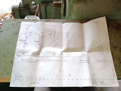
 Bild
Handgezeichneter Schaltplan einer Motorsteuerung
mit Motorschutz, Vorschub langsam-schnell, Antrieb Motor, 3~, 27V, SL 29 30 31 32, Zentralschaltung L1 L2 L3 33 34 35 36 37 38 39 40 41 42 43 44 45 46 47 48 49 50 51 52 53 54 55
in „Danfoss VLT 2800 Fräsmaschine Endanschläge“ · Analoge Elektronik und Schaltungstechnik · · Schaltpläne
-
PDF
WM8978.pdf
very closely correlated with THD; see below Total Harmonic Distortion THD P =200mW, R = 8Ω, 0.04 % O L SPKVDD=3.3V -68 dB PO=320mW, R =L8Ω, 1.0 % SPKVDD=3.3V -40 dB PO=500mW, R =L8Ω, 0.02 % SPKVDD=5V -74 dB PO=860mW, R =L8Ω, 1.0 % SPKVDD=5V -40 dB Signal to Noise Ratio SNR SPKVDD=3.3V, 90 dB RL= 8Ω SPKVDD
in „GSM + GPS Modul von Pollin“ · Mikrocontroller und Digitale Elektronik ·
-
PDF
Datenblatt_NVSRAM_23LCV1024.pdf
PACKAGING INFORMATION 6.1 Package Marking Information 8-Lead PDIP (300 mil) Example XXXXXXXX 23LCVB I/Pe3 1L7 XXXXXNNN 0528 YYWW 8-Lead SOIC (3.90 mm) Example: XXXXXXXT 23LCVBI XXXXYYWW SN e3 0528 NNN 1L7 8-Lead TSSOP Example: XXXX 3LVB TYWW I837 NNN 1L7 Legend: XX...X Part number or part number code T Temperature
in „Probleme mit SRAM 23LCV1024“ · Mikrocontroller und Digitale Elektronik ·
-
PDF
AD9952arduino.pdf
************************************************************************************* 45 .def EncodL = r24 ; 46 .def EncodH = r25 ; 47 ;.def reg26 = r26 ; 48 ;.def reg27 = r27 ; 49 ;.def reg28 = r28 ; 50 ;.def reg29 = r29 ; 51 ; ZL = r30 ; Zeiger auf SRAM low 52 ; ZH = r31 ; Zeiger auf SRAM high 53
in „DDS-Chip mit einem AVR ansprechen“ · Mikrocontroller und Digitale Elektronik ·
-
PDF
Teile20.09..pdf
Reichelt Hauptteil 9,80 € 1 Stück 9,80 € 1 Platine LA 5,00 € 1 Stück 5,00 € 45,96 € USB 1 USB FT2232L Segor 6,38 € 1 Stück 6,38 € 1 Eprom 93LC56B/SN-ND Segor 0,53 € 1 Stück 0,53 € 1 Tantal Elko 495-2212-1-ND Digikey 0,20 € 1 Stück 0,20 € 1 Induktivität PCD1089CT-ND Digikey 0,20 € 1 Stück 0,20 € 1 Multiplexer
in „[S] Leute die einen Logic Analyzer (MiniLA) bauen wollen“ · Markt ·
-
PDF
MCP73837.pdf
L Hi-Z L initiate a recharge cycle. Placing a programming Constant Voltage L Hi-Z L resistor from the PROG1/2 input to V SS enables the Charge Complete - Standby Hi-Z L L device. Allowing the PROG1/2 input
in „Verständnissfrage - MCP73837“ · Mikrocontroller und Digitale Elektronik ·
-
PDF
LM2940T-10.0.pdf
LM2940IMPX-8.0 LM2940IMPX-9.0 LM2940IMPX-10 LM2940IMPX-12 LM2940IMPX-15 SOT-223 in Tape and Reel Marking L53B L54B L0EB L55B L56B L70B © 2006 National Semiconductor CorporatioDS008822 www.national.com C 4 Ordering Information (Continued) 9 2 The physical size of the SOT-223 is too small to contain the full
in „Low Drop Low Current Spannungsregler 10V“ · Analoge Elektronik und Schaltungstechnik ·
-
PDF
Datenblatt_Eurola_8-24kW.pdf
,0s, Trinkwasserseitiger Anschluß (Ans*/luß n(*/ DINĂ1988) B,o)(*/t)(r, Mün+un. Entl,,run. +,r Aus)l(s,l,0tun. K(ltw(ss,r S0*/,r/,0tsv,nt0l Tr0nkw(ss,r-0lt,r1 A)sp,rrv,nt0l Dru*km0n+,r,r Dur*/-lußr,.ul0,rv,nt0l ,ntspr,*/,n+ DIN1988Ć2 (E0n)(u w0r+ ,mp-o/l,n ) Aus.(), D,z. 1988 M(nom,t,r(ns*/luß Rü*k-lußv
in „Schaltplan/Hilfe bei Steuerung Eurola OC“ · Haus & Smart Home ·
-
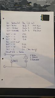
 Bild
Handschriftliche Notizen und Skizze zu Widerstandswerten und Schaltbild
Bedienteil (Bei Licht aus) ROT - BLAU Stufe 1 145 Ohm ROT - BRAUN Stufe 2 49 Ohm ROT - SCHWARZ Stufe 3 53 Ohm ROT - ∑ 1 Ω ROT - L 50 Ω ROT - N 0 Ω Bei Licht aus ROT - ∑ 0 Ω ROT - N 0 Ω ROT - L 0 Ω (Hochohmig) Schaltbild in Heube N ROT 1 BLAU 2 BRAUN 3 SCHWARZ L M M
in „Fehlersuche Dunstabzugshaube“ · Haus & Smart Home · · Fotos
-
PDF
LCD204B_DIS.pdf
Command Execution Command RS R/ DB 7 DB 6 DB5 DB 4 DB 3 DB2 DB1 DB0 Time Remark W (osc 250kHz) DISPLAY L L L L L L L L L H 1.64ms CLEAR RETURN L L L L L L L L H X 1.64ms Cursor move to first digit HOME ENTRY MODE L L L L L L L H I/D SH 42μs • I/D : Set cursor move direction SET H Increase I/D L Decrease • SH : Specifies shift of display H Display is shifted SH L Display is not shifted DISPLAY L L L L L L H D C B 42μs • Display ON/OFF H Display on D L Display off • Cursor H Cursor on C L Cursor off • Blinking H Blinking on B L Blinking off SHIFT L L L L L H S
in „LCD Problem“ · Mikrocontroller und Digitale Elektronik ·
-
PDF
LCD_202A.pdf
Command Execution Command RS R/W DB7 DB6 DB5 DB4 DB3 DB2 DB1 DB0 Time Remark (fosc 250kHz) DISPLAY L L L L L L L L L H 1.64ms CLEAR RETURN L L L L L L L L H X 1.64ms Cursor move to first digit HOME ENTRY MODE L L L L L L L H I/D SH 42μs • I/D : Set cursor move direction SET H Increase I/D L Decrease • SH : Specifies shift of display H Display is shifted SH L Display is not shifted DISPLAY L L L L L L H D C B 42μs • Display ON/OFF H Display on D L Display off • Cursor H Cursor on C L Cursor off • Blinking H Blinking on B L Blinking off SHIFT L L L L L H S
in „Fehler bei 4Bit LCD Init?“ · Mikrocontroller und Digitale Elektronik ·
-
PDF
LCD202a_Serie_DIS.pdf
Command Execution Command RS R/W DB7 DB6 DB5 DB4 DB3 DB2 DB1 DB0 Time Remark (fosc 250kHz) DISPLAY L L L L L L L L L H 1.64ms CLEAR RETURN L L L L L L L L H X 1.64ms Cursor move to first digit HOME ENTRY MODE L L L L L L L H I/D SH 42μs • I/D : Set cursor move direction SET H Increase I/D L Decrease • SH : Specifies shift of display H Display is shifted SH L Display is not shifted DISPLAY L L L L L L H D C B 42μs • Display ON/OFF H Display on D L Display off • Cursor H Cursor on C L Cursor off • Blinking H Blinking on B L Blinking off SHIFT L L L L L H S
in „LCD +Bascom zeigt 1. Zeile Nix 2. Zeile voll“ · Mikrocontroller und Digitale Elektronik ·
-
PDF
164a_series-v10.PDF
Command Execution Command RS R/W DB DB DB DB DB DB DB DB (f = Remark 7 6 5 4 3 2 1 0 250kHz) DISPLAY L L L L L L L L L H 1.64ms CLEAR RETURN HOME L L L L L L L L H X 1.64ms Cursor move to first digit ENTRY MODE L L L L L L L H I/D SH 42μs • I/D : Set cursor move direction SET H Increase I/D L Decrease • SH : Specifies shift of display H Display is shifted SH L Display is not shifted DISPLAY L L L L L L H D C B 42μs • Display ON/OFF H Display on D L Display off • Cursor H Cursor on C L Cursor off • Blinking H Blinking on B L Blinking off SHIFT L L L L L H S
in „LCD Aufloesung“ · Mikrocontroller und Digitale Elektronik ·
-
PDF
LCD204B_DIS.pdf
Command Execution Command RS R/ DB 7 DB 6 DB5 DB 4 DB 3 DB2 DB1 DB0 Time Remark W (osc 250kHz) DISPLAY L L L L L L L L L H 1.64ms CLEAR RETURN L L L L L L L L H X 1.64ms Cursor move to first digit HOME ENTRY MODE L L L L L L L H I/D SH 42μs • I/D : Set cursor move direction SET H Increase I/D L Decrease • SH : Specifies shift of display H Display is shifted SH L Display is not shifted DISPLAY L L L L L L H D C B 42μs • Display ON/OFF H Display on D L Display off • Cursor H Cursor on C L Cursor off • Blinking H Blinking on B L Blinking off SHIFT L L L L L H S
-
PDF
20x4.pdf
Command Execution Command RS R/ DB 7 DB 6 DB5 DB 4 DB 3 DB2 DB1 DB0 Time Remark W (osc 250kHz) DISPLAY L L L L L L L L L H 1.64ms CLEAR RETURN L L L L L L L L H X 1.64ms Cursor move to first digit HOME ENTRY MODE L L L L L L L H I/D SH 42μs • I/D : Set cursor move direction SET H Increase I/D L Decrease • SH : Specifies shift of display H Display is shifted SH L Display is not shifted DISPLAY L L L L L L H D C B 42μs • Display ON/OFF H Display on D L Display off • Cursor H Cursor on C L Cursor off • Blinking H Blinking on B L Blinking off SHIFT L L L L L H S
-
PDF
DIS.pdf
Command Execution Command RS R/W DB7 DB6 DB5 DB4 DB3 DB2 DB1 DB0 Time Remark (fosc 250kHz) DISPLAY L L L L L L L L L H 1.64ms CLEAR RETURN L L L L L L L L H X 1.64ms Cursor move to first digit HOME ENTRY MODE L L L L L L L H I/D SH 42μs • I/D : Set cursor move direction SET H Increase I/D L Decrease • SH : Specifies shift of display H Display is shifted SH L Display is not shifted DISPLAY L L L L L L H D C B 42μs • Display ON/OFF H Display on D L Display off • Cursor H Cursor on C L Cursor off • Blinking H Blinking on B L Blinking off SHIFT L L L L L H S
in „LCD Ansteuerung, was tun“ · Mikrocontroller und Digitale Elektronik ·
-
PDF
LCD.pdf
Command Execution Command RS R/ DB 7 DB 6 DB5 DB 4 DB 3 DB2 DB1 DB0 Time Remark W (osc 250kHz) DISPLAY L L L L L L L L L H 1.64ms CLEAR RETURN L L L L L L L L H X 1.64ms Cursor move to first digit HOME ENTRY MODE L L L L L L L H I/D SH 42μs • I/D : Set cursor move direction SET H Increase I/D L Decrease • SH : Specifies shift of display H Display is shifted SH L Display is not shifted DISPLAY L L L L L L H D C B 42μs • Display ON/OFF H Display on D L Display off • Cursor H Cursor on C L Cursor off • Blinking H Blinking on B L Blinking off SHIFT L L L L L H S
in „lcd string "ü" darstellen.“ · Mikrocontroller und Digitale Elektronik ·
-
PDF
DIS.pdf
Command Execution Command RS R/ DB 7 DB 6 DB5 DB 4 DB 3 DB2 DB1 DB0 Time Remark W (osc 250kHz) DISPLAY L L L L L L L L L H 1.64ms CLEAR RETURN L L L L L L L L H X 1.64ms Cursor move to first digit HOME ENTRY MODE L L L L L L L H I/D SH 42μs • I/D : Set cursor move direction SET H Increase I/D L Decrease • SH : Specifies shift of display H Display is shifted SH L Display is not shifted DISPLAY L L L L L L H D C B 42μs • Display ON/OFF H Display on D L Display off • Cursor H Cursor on C L Cursor off • Blinking H Blinking on B L Blinking off SHIFT L L L L L H S
in „Ansteuern eines LCD über ATmega16“ · Mikrocontroller und Digitale Elektronik ·
-
PDF
DIS.pdf
Command Execution Command RS R/W DB7 DB6 DB5 DB4 DB3 DB2 DB1 DB0 Time Remark (fosc 250kHz) DISPLAY L L L L L L L L L H 1.64ms CLEAR RETURN L L L L L L L L H X 1.64ms Cursor move to first digit HOME ENTRY MODE L L L L L L L H I/D SH 42μs • I/D : Set cursor move direction SET H Increase I/D L Decrease • SH : Specifies shift of display H Display is shifted SH L Display is not shifted DISPLAY L L L L L L H D C B 42μs • Display ON/OFF H Display on D L Display off • Cursor H Cursor on C L Cursor off • Blinking H Blinking on B L Blinking off SHIFT L L L L L H S
in „LCD 202A Conrad und Atmega 8“ · Mikrocontroller und Digitale Elektronik ·
-
PDF
DIS_1_.pdf
Command Execution Command RS R/W DB7 DB6 DB5 DB4 DB3 DB2 DB1 DB0 Time Remark (fosc 250kHz) DISPLAY L L L L L L L L L H 1.64ms CLEAR RETURN L L L L L L L L H X 1.64ms Cursor move to first digit HOME ENTRY MODE L L L L L L L H I/D SH 42μs • I/D : Set cursor move direction SET H Increase I/D L Decrease • SH : Specifies shift of display H Display is shifted SH L Display is not shifted DISPLAY L L L L L L H D C B 42μs • Display ON/OFF H Display on D L Display off • Cursor H Cursor on C L Cursor off • Blinking H Blinking on B L Blinking off SHIFT L L L L L H S
in „LCD Ansteuerung“ · Mikrocontroller und Digitale Elektronik ·
-
 Bild
Foto einer bestückten Leiterplatte
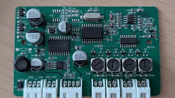
R40, R41, R42, R43, R44, R45, R46, R48, R49, U2, HCF4052, EZX521, REV1.0, D21, Q6, D20, D19, D18, L1, L2, L3, L4, R15, R31, R37, R49, J1, J2, J3, J4, GND, VDD, SPK, GND, OUT, VSS, IN, VSS, C30, C27, C3, C4, C5, C12, R53, R60, R61, R52, C32, Q7, R50, R45, R39, R48, U7, C31, U5, C52, C51, C50, C49, C48
in „Abstandssensorenfeinfühligkeit ändern“ · Fahrzeugelektronik · · Platinenfotos
-
PDF
L6562N_PFC__STM.pdf
to 265V) 7 °C/W heat sink 450V 6 4 C2 10nF C29 R3 22 µF C4 R9 R10 R13 22 kΩ 25V 100 nF 0.33Ω 0.3Ω 9.53 Ω 1W 1W - Boost Inductor Spec: EB0057-C (COILCRAFT) Figure 24. Demo board (EVAL6562-80W, Wide-range mains): Electrical schematic R4 R5 T D8 C5 12 nF D1 NTC R11 Vo=400V 180 kΩ 180 k 1N4150 R14 STTH1L06
in „PFC Controller (L6562) statt normalem SNT ControllerSNT“ · Analoge Elektronik und Schaltungstechnik ·
-
PDF
High_Performance_Flash_and_Arc_Lamps_-_PerkinElmer.pdf
lamp K knowo C The standard design procedure for flashlamp is found from equation (4). – single mesh L/C drive networks was originated T c by J.P. Markiewicz and J.L. Emmett (reference 1). (b) L is then calculated from equation (5) h n (c) Finally o is calculated from equation (6) c The starting point
in „Projekt: Leistungsstarkes Blitzgerät aus 12 Volt“ · Analoge Elektronik und Schaltungstechnik ·
-
PDF
Perkin_Elmer_Flash___Arc_Tubes.pdf
lamp K knowo C The standard design procedure for flashlamp is found from equation (4). – single mesh L/C drive networks was originated T c by J.P. Markiewicz and J.L. Emmett (reference 1). (b) L is then calculated from equation (5) h n (c) Finally o is calculated from equation (6) c The starting point
in „Reparatur (UW) Blitzgerät möglich?“ · Mikrocontroller und Digitale Elektronik ·
-
PDF
14_hoofdstuk14.pdf
AUD_BCLK J2I 24 44 LED6 AUD_DACDAT J2J 25 47 LED5 AUD_DACLRC J2K 26 53 LED4 AUD_ADCDAT J2L 27 55 LED3 AUD_ADCLRC J2M 28 57 LED2 AUD_WCK J2N 29 61 LED1 SCLK J2O 30 62 LED0 SDIN Hoofdstuk 14 Lattice development board LFXP2-5E - 55 - Connector Gemeen- Dochterbordje dochterbordje
-
PDF
m3s_v2-0.pdf
dem Gera enamen. 1..256 Daten 0..255 NULL Datenspeicher zuletzt empfangener Daten mit variabler Byte L nge zwischen 1 und 256 Bytes DatenUpperBound 8 Bit 0..255 0 Gibt den h chsten Arrayindex der erwarteten Daten an (und somit die Daten ange). Haben empfangene Daten- pakete di▯erierende L ngen, werden
in „API-Feedback / Protokollfeedback: Kommunikationsstack für serielle Bussysteme“ · Mikrocontroller und Digitale Elektronik ·
-
Datei
Nixie_Uhr_4_1.c
== 1) && (I1 == 0) && (J1 == 0) && (K1 == 0)) H2 = 0; //'decodieren der zehner stelle Stunden if ((L1 == 1) && (M1 == 0)) H3 = 10; if ((L1 == 0) && (M1 == 1)) H3 = 20; if ((L1 == 0) && (M1 == 0)) H3 = 0; // Uhrzeit zusammensetzen M = M3 + M; if (H2 == 9) { H2 = 0; H = H3; } else H = (H2 + 1) + H3; }
in „Win AVR funktioniert nicht richtig !! Hilfe.“ · Mikrocontroller und Digitale Elektronik ·
-
PDF
CS4344-45-46-48_F1.pdf
Single-Speed Stopband Rejection Figure 14. Single-Speed Transition Band 0 -1 0.05 -2 0 -3 -4 -0.05 B d e d u l -5 l -0.1 p m A A -6 -0.15 -7 -0.2 -8 -0.25 -9 -10 0 0.05 0.1 0.15 0.2 0.25 0.3 0.35 0.4 0.45 0.5 0.45 0.46 0.47 0.48 0.49 0.5 0.51 0.52 0.53 0.54 0.55 Frequency (normalized to Fs) Frequency (normalized
in „STA015, CS4344 Platinencheck“ · Mikrocontroller und Digitale Elektronik ·
-
PDF
01_Sicherungsautomaten.pdf
Kennziffer: 2 1 für 1polig Gewicht [kg]: 0,245 für 2polig 0,490 für 3polig 0,735 für 4polig 0,980 l Auslösecharakteristik D auf Anfrage l Technische Daten siehe ab Seite 1/126 l Technischen Spezialkatalog kostenlos anfordern 1/53 Hochleistungs-Sicherungsautomaten mit Käfigklemme, * Baureihe S 800 C
in „Kurzschlussstrom“ · Offtopic ·
-
Datei
frequ.c
// H: 0xF9 L:0xE0=8,929Hz // H: 0xFA L:0x00=9,174Hz // H: 0xFE L:0x00=26,04Hz // H: 0xFA L:0x20=9,346HZ // H: 0xFE L:0x20=27,47Hz // H: 0xFA L:0x40=9,524HZ // H: 0xFE L:0x40=29,41Hz // H: 0xFA L:0x60=9,709HZ // H
in „Sinuserzeugung im c“ · Mikrocontroller und Digitale Elektronik ·
-
Datei
init_ili9320.h
LCD_SCL_CLR; LCD_SCL_SET; Data<<=1; } #endif LCD_CS_SET; } void Lcd_WriteData16Bit(u8 DataH,u8 DataL) { Lcd_WriteData(DataH); Lcd_WriteData(DataL); } void Lcd_WriteIndex16Bit(u8 DataH,u8 DataL) { Lcd_WriteIndex(DataH); Lcd_WriteIndex(DataL); } void Lcd_Reset(void) { LCD_RST_SET; _delay_ms(1); LCD_RST_CLR
in „2.2" 176x220 SPI TFT - Kennt jemand dieses Modell?“ · Mikrocontroller und Digitale Elektronik ·
-
PDF
datenblatt-179345-stmicroelectronics-l78s05cv-spannungsregler-linear-typ78-to-220ab-positiv-fest-5-v-2-a.pdf
external components to obtain adjustable voltages and currents. Table 1. Device summary Part numbers L78S05 L78S09 L78S12 L78S18 L78S05C L78S09C L78S12C L78S18C L78S75 L78S10 L78S15 L78S24 L78S75C L78S10C L78S15C L78S24C May 2012 Doc ID 2148 Rev 7 1/39 This is information on a product in full production
in „TL431 schwankt wie verrückt!“ · Analoge Elektronik und Schaltungstechnik ·
-
PDF
LC-R123R4PG.pdf
Battery temperature (°C) 20.0 DISCHARGECHARACTERISTICS 20.0 20.0 )15.15.0 ( V 20.0 e e )t5a) 15.0 o l( l10ve050 t Vtg 3.4A3.4A 0.850.85A 0.10.17A m eo 10.10.2A e10al 10.0 n Tn0 3.4A 3.4A 0.850.85A 0.170.17A m li10.0 10.210.2A e ar 3.4A 0.85A 0.17A T 5.0 5.0 10.2A r 0T0 5.0 0 0 1 1 2 2 3 3 5 5 7 7 10
in „Autoradio mit externem Netzteil +Pufferakku sowie ladegerät für Akku.“ · Analoge Elektronik und Schaltungstechnik ·