-
Datei
LCMUT_measurement_ui.py
layout_bottom, 1) self.setLayout(layout) # Serielle Ports scannen self.com_ports = [] self.com_names = [] for x in serial.tools.list_ports.comports(): self.com_ports.append(x[0]) self.com_names.append(x[1]) self.combo_com_ports.addItem(x[0] + ' - ' + x[1]) # DAQ Thread starten self.daq = DAQThread() self.thread
in „Mikrocontroller mit Python auswerten“ · Mikrocontroller und Digitale Elektronik ·
-
PDF
WEEE-Richtlinie-2008_Begriffe.pdf
und des Rates vom 20. Dezember 1994 über Verpackungen und Verpackungsabfälle ( ), der Richtlinie 2000/53/EG des Europäischen 13 Parlaments und des Rates vom 18. September 2000 über Altfahrzeuge ( ), der Richtlinie 2002/96/EG des Europäischen Parlaments 14 und des Rates vom 27. Januar 2003 über Elektro
in „iiyama Monitor geht aus - Reparatur“ · Analoge Elektronik und Schaltungstechnik ·
-
PDF
DRV8825-Datasheet.pdf
time 3 µs DEG TSD Thermal shutdown temperature Die temperature 150 160 180 °C CURRENT CONTROL REF xVREF input current V (xVREF) 3.3 V –3 3 μA VTRIP xISENSE trip voltage V (xVREF) 3.3 V, 100% current setting 635 660 685 mV V (xVREF) 3.3 V, 5% current setting –25% 25% Current trip accuracy V (xVREF)
in „Nano Shield zerstört Nano“ · Mikrocontroller und Digitale Elektronik ·
-
PDF
WT11_Data_Sheet.pdf
0.004096 Figure 9: Baud rate calculation formula Baud rate Persistent store values Error Hex Dec 1200 0x0005 5 1.73% 2400 0x000a 10 1.73% 4800 0x0014 20 1.73% 9600 0x0027 39 -0.82% 19200 0x004f 79 0.45% 38400 0x009d 157 -0.18% 57600 0x00ec 263 0.03% 76800 0x013b 315 0.14% 115200 472 0x01d8 0.03% 230400 0x03b0 944 0.03% 460800 0x075f 1887 -0.02% 921600 0x0ebf 3775 0.00% 1382400 0x161e 5662 -0.01% 1843200 0x1d7e 7550 0.00% 2765800 0x2c3d 11325 0.00% Table 8: UART baud rates and error values 4.1.1 UART Configuration
in „WT11 von Bluegiga, Registrierung?“ · Mikrocontroller und Digitale Elektronik ·
-
PDF
71v416.pdf
Output I/O 7 Buffer Low 8 Byte 8 Write I/O 0 Buffer BHE Byte Enable Buffers BLE 3624 drw 01 AUGUST 2000 1 ©2000IntegratedDeviceTechnology,Inc. DSC-3624/04 IDT71V416S, IDT71V416L, 3.3V CMOS Static RAM 4 Meg (256K x 16-Bit) Commercial and Industrial Temperature Ranges Pin Configurations - SOJ/TSOP Pin Configurations
-
PDF
qbd-manual-en.pdf
Storage Temperature -40...+85C Humidity 90%, non-condensing MECHANICAL SPECIFICATION Size (LxWxH) 110x80x25 mm Weight 0,1 kg DRAWINGS Part number table Part Number HVmax HVmin QBD-6024-DN QBD-6024-UP 6000 2400 QBD-5020-DN QBD-5020-UP 5000 2000 QBD-4016-DN 4000 1600 QBD-4016-UP QBD-3012-DN 3000 1200 QBD-3012-UP QBD-2008-DN QBD-2008-UP 2000 800 Suffics “DN” means pull-down scheme, “UP” – push-up scheme (see also Pulse parameters section) Typical output time scale: 2us / div time scale: 100ns / div time scale: 10ns / div
in „Impulserzeugung via Blumleingenerator“ · HF, Funk und Felder ·
-
Bild
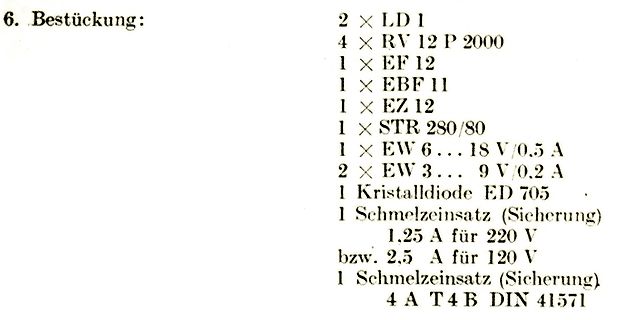
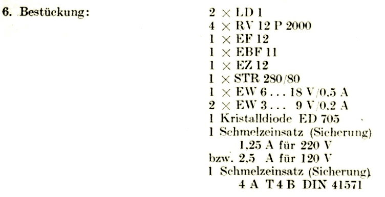
Stückliste elektronischer Bauteile
6. Bestückung: 2 x LD 1 4 x RV 12 P 2000 1 x EF 12 1 x EBF 11 1 x EZ 12 1 x STR 280/80 1 x EW 6 ... 18 V/0.5 A 2 x EW 3 ... 9 V/0.2 A 1 Kristalldiode ED 705 1 Schmelzeinsatz (Sicherung) 1.25 A für 220 V bzw. 2.5 A für
in „Biete UKW Meßgenerator 2006a - Funkwerk Erfurt, VEB, RFT (DDR)“ · Markt · · Screenshots
-
Datei
GTR_Neu_IV.c
ms; uint32_t Wait1; uint32_t Wait2; uint32_t Timeout1; uint32_t Timeout2; uint8_t SendHeader [] = {0x3a,'V', 'A', 'L', 0x00, 'V','M', 0x00,0x01,0x00,0x01,'A', 0xff,0xff,0xff,0xff,0xff,0xff,0xff,'V','a', 'r', 'i', 'a', 'b', 'l', 'e', 'R', 0x0A,0xff,0xff,0xff,0xff,0xff,0xff,0xff,0xff,0xff,0xff,0xff,0xff
in „Taschenrechner Kommunikation“ · Mikrocontroller und Digitale Elektronik ·
-
PDF
pjb_einf_hrung-bascom-avr_de.pdf
Almere-Haven HOLLAND http://www.mcselec.com/ Die Software ist lauffähig unter Windows 95, 98, NT, 2000 und XP. Der Preis für die Basisversion liegt bei 79,00 €. Was ist bei der Installation zu beachten? Die Installation wird mit setup.exe gestartet und ist unproblematisch. Bei der Demo ist zu beachten
in „LCD Ansteuerung“ · Mikrocontroller und Digitale Elektronik ·
-
PDF
CZX.pdf
U m 100 V D. C., t = 1 min: Ri≥ 15000 MΩ for C ≤ 0,33 μF Marking KNB1560 for C > 1μF to 2,2μF: Ri X Cn≥ 5000 s for C > 0,33 μF Capacitance Tolerance Dielectr0c loss tandat f =1 kHz -3 KNB1560 MKP and 20 C: ≤ 1 x 10 275V AC _ _ _ μF ± _ _40/110/56/B Soldering: IEC publ. 60068-2-20, max. 2 s 0 Soldering
in „Maschinensteuerung Widerstand verbrannt“ · Analoge Elektronik und Schaltungstechnik ·
-
PDF
2N5088-89.pdf
A 0.175 0.205 4.45 5.20 B 0.170 0.210 4.32 5.33 C 0.125 0.165 3.18 4.19 D 0.016 0.021 0.407 0.533 X X D G 0.045 0.055 1.15 1.39 H 0.095 0.105 2.42 2.66 G J 0.015 0.020 0.39 0.50 H J K 0.500 −−− 12.70 −−− L 0.250 −−− 6.35 −−− V C N 0.080 0.105 2.04 2.66 SECTION X−X P −−− 0.100 −−− 2.54 1 R 0.115 −−−
in „rauscharmer NPN min 200v gesucht“ · Analoge Elektronik und Schaltungstechnik ·
-
Bild
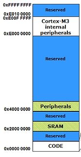
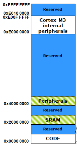
Speicherabbild Cortex-M3 Adressraum
0xFFF FFFF Reserved 0xE010 0000 0xE00F FFFF Cortex-M3 internal peripherals 0xE000 0000 Reserved 0x4000 0000 Peripherals Reserved 0x2000 0000 SRAM Reserved 0x0000 0000 CODE
in „Alternative Speicheraufteilung bei µC“ · Mikrocontroller und Digitale Elektronik · · Screenshots
-
PDF
K7S41-K7S41GX.pdf
2-3 2-3 1-2 9.5x 2-3 1-2 2-3 2-3 1-2 10x 1-2 2-3 2-3 2-3 1-2 10.5x 2-3 2-3 2-3 2-3 1-2 11x 1-2 1-2 1-2 1-2 1-2 11.5x 2-3 1-2 1-2 1-2 1-2 12x 1-2 2-3 1-2 1-2 1-2 12.5x 2-3 2-3 1-2 1-2 1-2 13x 1-2 1-2 2-3 1-2 2-3 13.5x
in „Asrock Board K7S41 mit SATA 1 Terabyte Festplatte“ · PC Hard- und Software ·
-
Bild
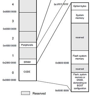
Speicherabbild eines Mikrocontrollers
4 0x1FFF FFFF Option bytes 0x8000 0000 3 System memory 0x6000 0000 2 reserved 0x4000 0000 Peripherals 1 0x0800 0000 Flash system memory 0x2000 0000 SRAM reserved 0 0x0000 0000 CODE Flash, system memory or
in „Firmwareupdate STM32 per KNX“ · Mikrocontroller und Digitale Elektronik · · Diagramme
-
PDF
X100-LEB_LET_A2A.pdf
Lambertian Emitter (120°) Abstrahlwinkel: Lambertscher Strahler (120°) light emitting surface® typ. 2.1 x 2.1 mm² Abstrahlende Fläche: typ® 2,1 x 2,1 mm² technology: ThInGaN Technologie: ThInGaN Luminance: 14*10 cd/m² (true green), Leuchtdichte: 14*10 cd/m² (true green), 3.5*10 6cd/m² (blue) 3,5*10 cd/m²
in „[V] Hochleistungs-LED-Module auf Metallkernplatine“ · Markt ·
-
Datei
Konv2.c
=2000; char MonatName[12][12]={"Jan","Feb","Mar","Apr","Mai","Jun","Jul","Aug","Sep","Okt","Nov","Dez"}; double MaxWert=1.79769e+308,MinWert=-1.79769e+308; struct stat src_stat; time_t altzeit,aktzeit; time_t
-
Datei
Konv2.c
=2000; char MonatName[12][12]={"Jan","Feb","Mar","Apr","Mai","Jun","Jul","Aug","Sep","Okt","Nov","Dez"}; double MaxWert=1.79769e+308,MinWert=-1.79769e+308; struct stat src_stat; time_t altzeit,aktzeit; time_t
-
Bild
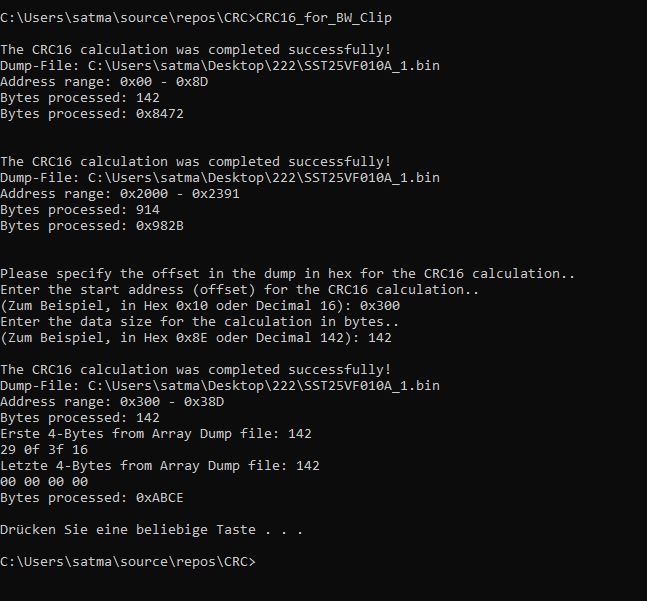
Konsole mit CRC16-Berechnungsergebnissen
was completed successfully! Dump-File: C:\Users\satma\Desktop\222\SST25VF010A_1.bin Address range: 0x000 - 0x8D Bytes processed: 142 Bytes processed: 0x8472 The CRC16 calculation was completed successfully! Dump-File: C:\Users\satma\Desktop\222\SST25VF010A_1.bin Address range: 0x2000 - 0x2391 Bytes processed: 914 Bytes processed: 0x982B Please specify the offset in the dump in hex for the CRC16 calculation.. Enter the start address (offset) for the CRC16 calculation.. (Zum Beispiel, in Hex 0x10 oder Decimal 16): 0x300 Enter the
in „Reset BW Clip“ · Mikrocontroller und Digitale Elektronik · · Screenshots
-
PDF
GD32F350xx_DS_v1.1.pdf
0x4000 3000 - 0x4000 33FF FWDGT 0x4000 2C00 - 0x4000 2FFF WWDGT 0x4000 2800 - 0x4000 2BFF RTC 0x4000 2400 - 0x4000 27FF Reserved 0x4000 2000 - 0x4000 23FF TIMER13 0x4000 1400 - 0x4000 1FFF Reserved 0x4000 1000 - 0x4000 13FF TIMER5 0x4000 0800 - 0x4000 0FFF Reserved 0x4000 0400 - 0x4000 07FF TIMER2 0x4000 0000 - 0x4000 03FF TIMER1 0x2000 5000 - 0x3FFF FFFF Reserved SRAM 0x2000 0000 - 0x2000 4FFF SRAM 0x1FFF FC00
in „"NUCLEO"-Borads von GigaDevice“ · Mikrocontroller und Digitale Elektronik ·
-
Datei
PSOne.h
* Created on: 08.10.2012 * Author: gawin */ #ifndef PSONE_H_ #define PSONE_H_ #define PSOne_Left 0x0001 #define PSOne_Down 0x0002 #define PSOne_Right 0x0004 #define PSOne_Up 0x0008 #define PSOne_Start 0x0010 #define PSOne_JoyR 0x0020 // Joystick rechts drücken #define PSOne_JoyL 0x0040 // Joystick links drücken #define PSOne_Select 0x0080 #define PSOne_Sqr 0x0100 #define PSOne_X 0x0200 #define PSOne_O 0x0400 #define PSOne_Tri 0x0800 #define PSOne_R1 0x1000 #define PSOne_L1 0x2000 #define PSOne_R2 0x4000 #define PSOne_L2 0x8000 typedef
-
Datei
cleanShowLog.m
the are disturbances cleanIdx=x<1000; t(cleanIdx)=[]; x(cleanIdx)=[]; # moving average over 24 ticks to smooth encoder slot variations wndw = 24; %# sliding window size x = filter(ones(wndw,1)/wndw, 1, x); #remove run in of moving average t=t(wndw:end); x=x(wndw:end); if 0 #subplot(2,1,1); plot(x); xlabel("n"); ylabel("dt [us]"); ylim([0,10000]); end if 1 #subplot(2,1,2); encoderTicks=24; measuredFrequency_Hz=1e6./x; rounds_per_sec=measuredFrequency_Hz
-
PDF
2_08.pdf
DISPLAY h s h Anfangs - Endadresse (HEX) e Displaytyp Bemerkung Ä 1.Zeile 2.Zeile 3.Zeile 4.Zeile d 1x8 $00-$07 r 1x16 $00-$0F MUX 1:8 n $00-$07 MUX 1:16 (linke Hälfte) g 1x16(8+8) o $40-$47 (rechte Hälfte) w 1x20 $00-$13 e 1x40 $00-$27 r 2x8 $00-$07 $40-$47 c 2x12 $00-$0B $40-$4B i 2x16 $00-$0F $40-$4F t 2x20 $00-$13 $40-$53 m v 2x24 $00-$17 $40-$57 r 2x40 $00-$27 $40-$67 e 4x16 $00-$0F $40-$4F $10-$1F $50-$5F h 4x20 $00-$13 $40-$53 $14-$27 $54-$67 t $00-$27 $40-$67 - - 1. Kontroller (Enable 1) n 4x40 -
in „Problem LCD 2x8 Zeichen“ · Mikrocontroller und Digitale Elektronik ·
-
Datei
mt7623n-bananapi-bpi-r2.dts.txt
interrupt-controller@10211000 { compatible = "arm,cortex-a7-gic"; interrupt-controller; #interrupt-cells = <0x03>; interrupt-parent = <0x0e>; reg = <0x00 0x10211000 0x00 0x1000 0x00 0x10212000 0x00 0x2000 0x00 0x10214000 0x00 0x2000 0x00 0x10216000 0x00 0x2000>; phandle = <0x0e>; }; adc@11001000 { compatible
in „ADC- und DAC-Experimente mit PCF8591 auf Banana Pi SBCs (WiringPi, i2c-tools)“ · Mikrocontroller und Digitale Elektronik ·
-
Datei
XLCD_Subs_DWD.c
Clock pin made low // Delay for 15ms to allow for LCD Power on reset DelayPORXLCD(); Delay1KTCYx(2000); Delay1KTCYx(2000); //WriteCmdXLCD(0x30); PORTA =0x30; E_PIN = 1; // Clock command in DelayFor18TCY(); E_PIN = 0; Delay1KTCYx(5); E_PIN = 1; // Clock command in DelayFor18TCY(); E_PIN = 0; Delay1KTCYx
in „Programmer, Debugger problem mit MPLAB - PIC 18f4520“ · Mikrocontroller und Digitale Elektronik ·
-
PDF
PMOLED_2.4_WHITE_P19706-A01_3PF0MIM9J.pdf
RiTdisplay. http://www.ritdisplay.com 4. MECHANICAL DATA NO ITEM SPECIFICATION UNIT 1 Dot Matrix 128 (W) x 64 (H) dot 2 2 Dot Size 0.4 (W) x 0.4 (H) mm 2 3 Dot Pitch 0.43 (W) x 0.43 (H) mm 4 Aperture Rate 86 % 5 Active Area 55.01 (W) x 27.49 (H) mm 2 6 Panel Size 60.5 (W) x 37 (H) mm 2 7* Panel Thickness
-
Datei
lm358_inv_amp_4.txt
<cir f="1" ts="0.000005" ic="382.76258214399064" cb="66" pb="43" vr="5" mts="5e-11"> <a x="240 208 336 208" f="8" ma="15" mi="-15" ga="100000"/> <O x="336 208 400 208" f="0" sc="0"/> <w x="336 144 336 208" f="0"/> <w x="240 192 176 192" f="0"/> <w x="176 192 176 144" f="0"/> <p x="336 208
in „LM358 als Verstärker - stimmt das denn so?“ · Analoge Elektronik und Schaltungstechnik ·
-
Datei
VFD_TEST.ino
SW_SERIAL_UNUSED_PIN=0; SoftwareSerial Serial1t(SW_SERIAL_UNUSED_PIN, SS_TXPin); byte helper1[] = { 0x00, 0x01, 0x02, 0x03, 0x04, 0x05, 0x06, 0x07, 0x08, 0x09, 0x0A, 0x0B, 0x0C, 0x0D, 0x0E, 0x0F, 0x10, 0x11, 0x12, 0x13 }; byte helper2[] = { 0x14, 0x15, 0x16, 0x17, 0x18, 0x19, 0x1A, 0x1B, 0x1C, 0x1D, 0x1E, 0x1F, 0x20, 0x21, 0x22, 0x23, 0x24, 0x25, 0x26, 0x27 }; String centerString(String text); void setup() { delay(2000); Serial1t.begin(9600); Serial1t.write(0x1B); Serial1t.write(0x05); Serial1t.write(0x1B
in „Hat schon jemand was mit dem FUJITSU VF60 Display gemacht?“ · Mikrocontroller und Digitale Elektronik ·
-
Bild
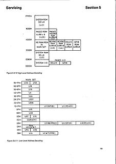
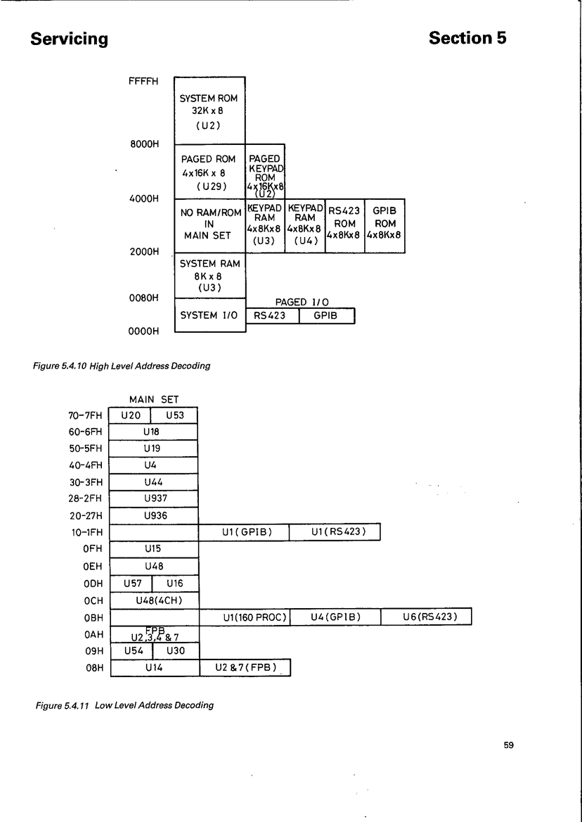
Blockschaltbilder der Adressdekodierung
Servicing Section 5 FFFFH SYSTEM ROM 32K x 8 (U2) 8000H PAGED ROM 4x16K x 8 (U29) PAGED KEYPAD ROM 4x8K x 8 (U2) 4000H NO RAM/ROM IN MAIN SET KEYPAD RAM 4x8K x 8 (U3) RS423 ROM 4x8K x 8 (U4) GPIB ROM 4x8K x 8 2000H SYSTEM RAM 8K x 8 (U3) 0080H
in „MC6809 + Gould 1504 Reverse-Engineering“ · Mikrocontroller und Digitale Elektronik · · Diagramme
-
Datei
ad5932.h
************/ #ifndef AD5932_H #define AD5932_H // AD5932 Registeradressen #define AD5932_CONTROL 0x0000 #define AD5932_N_INC 0x1000 #define AD5932_DELTA_F_LOW 0x2000 #define AD5932_DELTA_F_HIGH 0x3000 #define AD5932_T_INT 0x4000 #define AD5932_FSTART_LOW 0xC000 #define AD5932_FSTART_HIGH 0xD000 //
in „DDS-Singalgenerator mit ATmega88 und DDS AD5932“ · Digitale Signalverarbeitung / DSP / Machine Learning ·
-
Datei
readme.txt
Tipps für alle die loszulassen, die mittels Sockets, sei es unter Linux oder Solaris, unter Windows 9x oder Windows NT/2000, Server und Clients schreiben wollen. Da dies mein erster Versuch einer Sammlung von Tipps zur Programmierung ist, bitte ich um rege Beteiligung am Feedback damit ich in Zukunft
-
PDF
cas19d17c.pdf
profile. * High Sensitivity and Reliability. * RoHS Compliance. ◆ Mechanical dimensions ( unit: mm ) . X 0 M 19.0 1.9 MAX. 6 . 3 20.0 MAX. 5 3 4 17.2 ◆ Suggested PCB layout( unit: mm) ◆ Schematic diagram ② 4 4 16.0 L 20.6 R ① L: Ferrite core coil inductance. R: Copper resistance. Please refer to the sales
in „Renault Espace IV Schlüsselkarten ohne ZV / Keyless Go“ · Fahrzeugelektronik ·
-
PDF
snubber_n1.pdf
load 6/7 APPLICATION NOTE An inductive load of 2000 VA - cosφ= 0.6 on 220 V - 50 Hz mains can be controlled with a triac 0.1 x x d(/dt )c specified @ (dV/dt) = 10 V/ s by using : R + < c Va with C = 30 nF and R = 3.5 kOhms 2 PR< 2.C.V af e = VM/Va< 1.9 with L = 100 mH Va = Vacx x ~sin φ r = 40 Ohms P R= 0.23 W With the same load 2000 VA - cos φ 0.6 on 220 V - 50 Hz mains and with the same triac : V M 332 V (choose a triac with V DRM = 400 V) . 3 DETERMINATION OF THE SNUBBER C
in „Mal wieder Motor und Triac und Ansteuerung“ · Mikrocontroller und Digitale Elektronik ·
-
Datei
x9119.h
/22/2000 * * And comments from https://www.mikrocontroller.net/topic/363869 * * This code is distributed under the GNU Public License * which can be found at http://www.gnu.org/licenses/gpl.txt */ #ifndef X9119
in „AVR TWI im Master Reciver Mode daten an slave schicken“ · Mikrocontroller und Digitale Elektronik ·
-
Bild
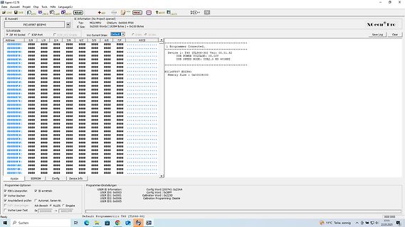
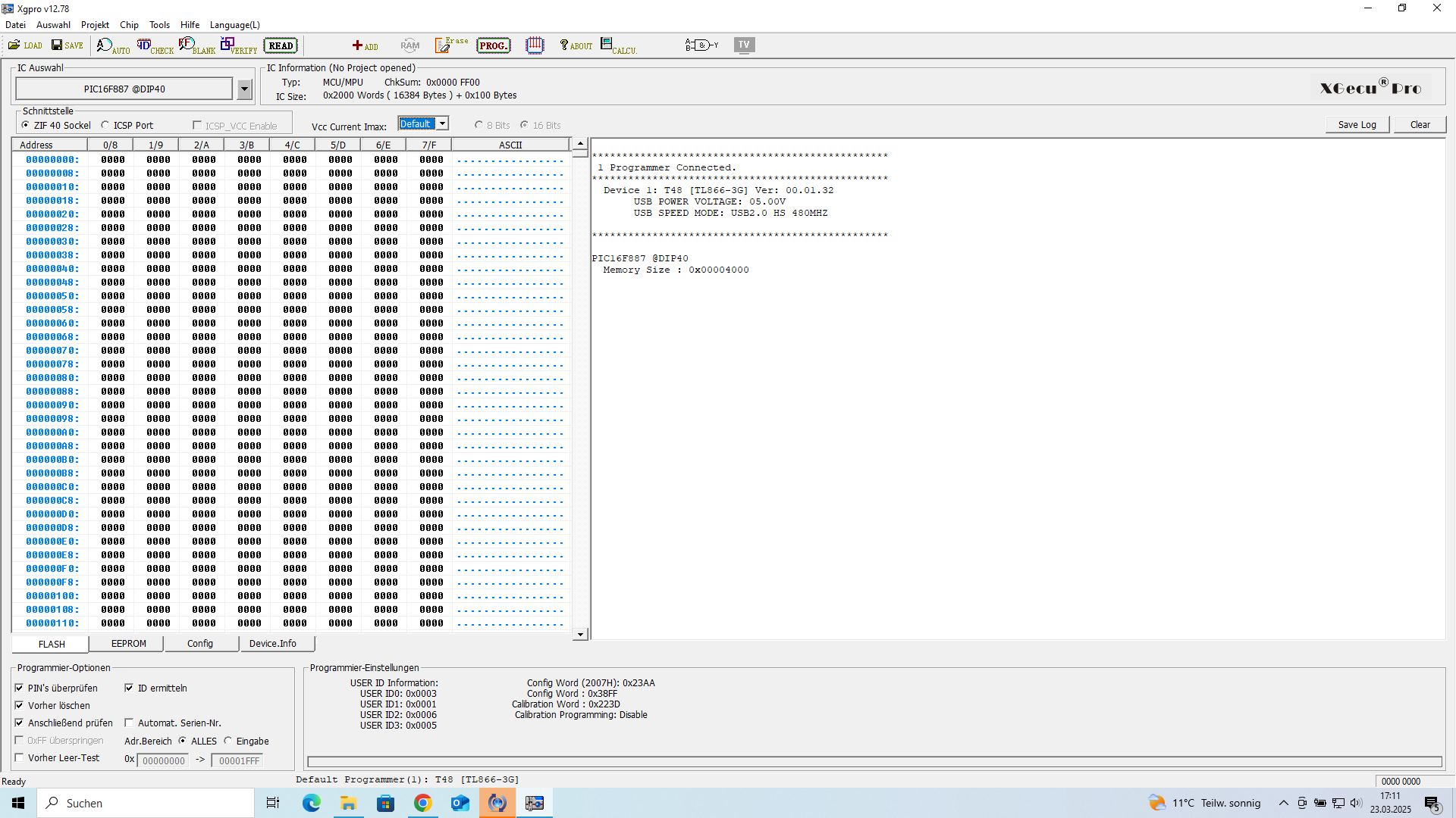
Software-Screenshot eines PIC-Programmierers
Xgeun Pro IC Information (No Project opened) Type: PIC16F857 MCU/MPU: PIC16F857 ChSum: 0x0000 FF00 IC: 0x2000 Bytes (16384 Bytes) @ 100 Bytes Address: 00/0, 17/0, ... ASCII 1 Programmer Connected. Device: 1 T48 [TL666-3G] Ver.: 00.01.32 USB SPEED MODE: USB2.0 MS 480MHZ PIC16F857 SDIP40 Memory Size: 0x00004000 FLASH EEPROM Config Device.info Programmer-Information: USER ID Information: Config Word (2007h): 0x23AA USER ID: 0x0003 Calibration Word (2007h): 0x23AA Calibration Word: 0x38FF USER ID2: 0x0003
in „EEPROM auslesen“ · Mikrocontroller und Digitale Elektronik · · Screenshots
-
PDF
tca9548a.pdf
Command Byte Definition CONTROL REGISTER BITS B7 B6 B5 B4 B3 B2 B1 B0 COMMAND 0 Channel 0 disabled X X X X X X X 1 Channel 0 enabled 0 Channel 1 disabled X X X X X X X 1 Channel 1 enabled 0 Channel 2 disabled X X X X X 1 X X Channel 2 enabled 0 Channel 3 disabled X X X X X X X 1 Channel 3 enabled 0 Channel 4 disabled X X X X X X X 1 Channel 4 enabled 0 Channel 5 disabled X X 1 X X X X X Channel 5 enabled 0 Channel 6 disabled X X X X X X X 1 Channel 6 enabled 0 Channel 7 disabled X X X X X X X 1 Channel 7 enabled 0
in „Unterschied TCA9548A und PCA9548A“ · Mikrocontroller und Digitale Elektronik ·
-
PDF
tca9548a.pdf
Command Byte Definition CONTROL REGISTER BITS B7 B6 B5 B4 B3 B2 B1 B0 COMMAND 0 Channel 0 disabled X X X X X X X 1 Channel 0 enabled 0 Channel 1 disabled X X X X X X X 1 Channel 1 enabled 0 Channel 2 disabled X X X X X 1 X X Channel 2 enabled 0 Channel 3 disabled X X X X X X X 1 Channel 3 enabled 0 Channel 4 disabled X X X X X X X 1 Channel 4 enabled 0 Channel 5 disabled X X 1 X X X X X Channel 5 enabled 0 Channel 6 disabled X X X X X X X 1 Channel 6 enabled 0 Channel 7 disabled X X X X X X X 1 Channel 7 enabled 0
in „Sensor Array ansprechen mit I2C - Unterschiede zu Mega2560 und Seeed RP2040“ · Mikrocontroller und Digitale Elektronik ·
-
PDF
Schaltplan_HEM_4PA.pdf
1 2 3 4 5 6 7 2X1 T1 BR1 80V, 1,5A AC S1 _ 2A mT U1 230 VAC + 78S05 C1 C2 C3 R1 R2 AC 1000uF 100nF 100nF R3 R4 2X2 10 kOhm 10 kOhm 10 kOhm 10 kOhm 1X1 1X2 1X3 A Aus 3bar Temp.1 A 1X4 1X5 1X6 Pri: 2x 115VAC Sek: 2x 12VAC
in „Probleme ATmega8“ · Mikrocontroller und Digitale Elektronik ·
-
Datei
Stoppuhr_8515.c
=Stoppuhr { if((STOPPUHR_TEST)==0) { timer1_init(STOPPUHR); //timer1 auf 100stel einstellen TCNT1=0x00; //timer_zählregister auf null... genaue zeitmessung ziffern=0; //variablen leeren hundertstel=0; zehntel=0; sekunde=0; z_sekunde=0; INT0_SET; //interrupt0 einschalten INT1_SET; //interrupt1 einschalten
in „AVR überspringt Wertzuweisung“ · Mikrocontroller und Digitale Elektronik ·
-
Bild
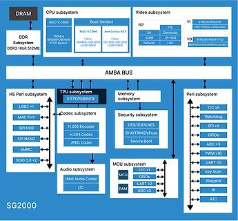
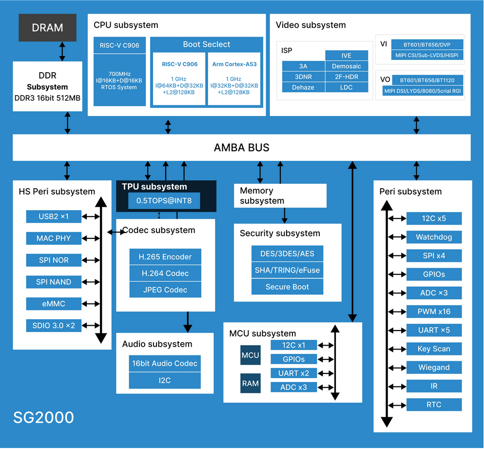
Blockschaltbild eines SG2000 Chipsystems
Sub-LVDS/HISPI, VO, BT601/BT656/BT1120, MIPI DSI/LVDS/8080/Scrial RGI, AMBA BUS, HS Peri subsystem, USB2 x1, MAC PHY, SPI NOR, SPI NAND, eMMC, SDIO 3.0 x2, TPU subsystem, 0.5TOPS@INT8, Codec subsystem, H.265 Encoder, H.264 Codec, JPEG Codec, Memory subsystem, Security subsystem, DES/3DES/AES, SHA/TRING/eFuse, Secure Boot, Peri subsystem, 12C x5, Watchdog, SPI x4, GPIOs, ADC x3, PWM x16, UART x5, Key Scan, Wiegand, IR, RTC, Audio subsystem, 16bit Audio Codec, I2C, MCU subsystem, MCU, GPIOs, UART x2, RAM, ADC x3, 12C x1, SG2000
in „OrangePi-Spielcomputer, FPGA-Abkündigungen, Arduino-Debugging und neue Chips“ · Mikrocontroller und Digitale Elektronik · · Diagramme
-
PDF
Bauanleitung_IRM.pdf
benötigt: • Multimeter DT-830B • Flachbandkabel 8-polig oder einzelne Litzen • Platine einseitig 5x8cm (oder größer, muss dann aber zugeschnitten werden) • Komponenten laut Schaltplan bzw. Bauteilliste Werkzeug: • Akkubohrmaschine inkl. Bohrer 3mm • Lötkolben + Lötzinn • Heißklebepistole • Equipment
in „TDR-Längenmessgerät auf Basis des Multimeter DT-830B“ · Projekte & Code ·
-
PDF
2CDC420009D0101.pdf
In Abschaltzeiten gemäß VDE 0664 Ausführung Fehlerstromart Abschaltzeiten bei Wechselfehlerströme 1 x I 2 x I 5 x I 500 A n n n pulsierende Gleichfehlerströme 1,4 x I n 2 x 1,4 x I n 5 x 1,4 x I n 500 A glatte Gleichfehlerströme 2 x I n 2 x 2 x I n 5 x 2 x I n 500 A Standard (unverzögert) bzw. kurzzeitverzögert
in „FI- Schutzschalter löst bei Erschütterung aus“ · Mikrocontroller und Digitale Elektronik ·
-
PDF
KS76.pdf
5 < 5 < 5 % Eigenrauschen(Effektivwert;0,5Hz-20kHz)•Residualnoise(RMS;0.5Hz-20kHz) a n wide band< 2000 < 300 < 2000 < 300 µg Rauschdichten • Noise densities 0,1 Hz a 100 30 100 30 µg/√Hz n 1 1 Hz a n 2 60 10 60 10 µg/√Hz 10 Hz a n 3 20 3 20 3 µg/√Hz 100 Hz a 2 1 2 1 µg/√Hz n 4 Konstantstromversorgung
in „Beschleunigungsmessung“ · Digitale Signalverarbeitung / DSP / Machine Learning ·
-
PDF
S-LH1080P-AUDIO-V17-Spec-20180504-1.pdf
的分辨率; DATA为非 FIFO, 通俗说是无法配太低档的方案, 若无法评估可联系技术员。成功案例:Mstar MTK 系列的 V59/56 等级以上,Mstar 系列的 安卓板,ARM 板, X86 主板等。 2. Features(特性说明) Features ( LVDS RX ): • Support LVDS Input modes: Single Link, Dual Link • Support input clock rate up to 150MHz • Support input color depth up to 10bit • Support De-SSC ( De-Spread
in „LVDS to HDMI Wandler S.LH1080P.AUDIO.V17“ · Projekte & Code ·
-
Bild
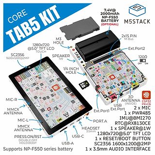
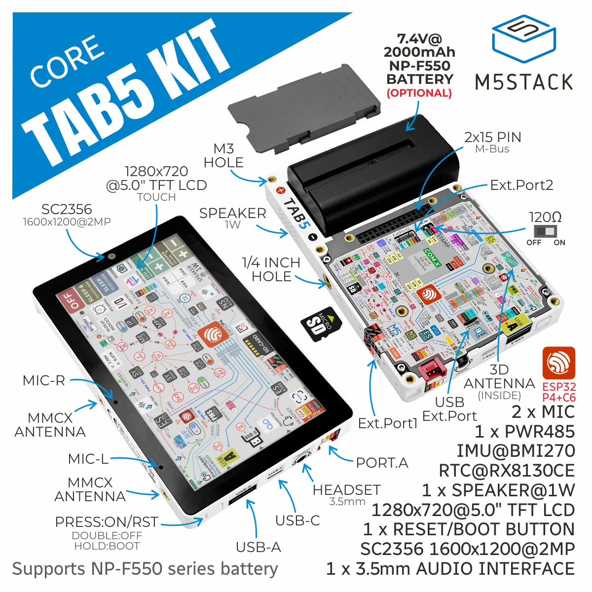
Produktübersicht M5Stack CORE TAB5 KIT
CORE TAB5 KIT 7.4V@ 2000mAh NP-F550 BATTERY (OPTIONAL) M5STACK M3 HOLE 2x15 PIN M-Bus Ext.Port2 120Ω OFF ON SPEAKER 1W 1/4 INCH HOLE SC2356 1600x1200@2MP TOUCH SD-CARD 3D ANTENNA (INSIDE) ESP32 P4+C6 2 x MIC MIC-R MMXC ANTENNA MIC-L MMXC ANTENNA PRESS:ON/RST DOUBLE:OFF HOLD:BOOT USB Ext.Port1 Ext.Port PORT.A RTC @BMI270 1 x SPEAKER@1W 1280x720@5.0" TFT LCD 1 x RESET/BOOT BUTTON SC2356 1600x1200@2MP 1 x 3.5mm AUDIO INTERFACE USB-A HEADSET 3.5mm USB-C
in „ARM-Umbenennungen, Erweiterungen des Raspberry Pi-Ökosystems uvam“ · Mikrocontroller und Digitale Elektronik · · Fotos
-
Datei
Ganganzeige_ADC.ino
Charliplexing * ATtiny25 */ // Widerstände der Gänge /Ohm #define GANG1 560 #define GANG2 1000 #define GANG3 2000 #define GANG4 3000 #define GANG5 5000 #define GANG6 15000 // externer Widerstand für Spannungsteiler /Ohm #define REXT 7500 #define ADCWERT(x) ((1024L*x)/(x+REXT)) uint16_t schwelle[5]; // Schaltschwellen
in „Spannung durch Spannungsteiler messen. Arduino“ · Mikrocontroller und Digitale Elektronik ·
-
PDF
JRXEWKbQXBFOb1fH.pdf
H8x, H9x, HAx, HBx, JBx, KKx, L1x, L2x, L3x, L4x, L5x, L6x, L7x, L8x, N1x, N2x, N3x, N4x, N5x, Q1x, Q2x, Q3x, Q4x, Q5x, Q6x v 2374-L1x, Q2x v 2378-R2x, R8x, R9x, RSx, RTx, RUx, RVx v 2379-R8x, R9x, RUx,
in „Lenovo T42 Ladeelektronik spielt verrückt“ · Mikrocontroller und Digitale Elektronik ·