-
PDF
0046274001518549145.pdf
(default) 900mA 1050mA 1400mA RATED POWER 60.3W OUTPUT DC VOLTAGE RANGE 2 ~ 90V 2 ~ 90V 2 ~ 86V 2 ~ 67V 2 ~ 57V 2 ~ 42V OPENCIRCUITVOLTAGE(max.) 102V 76V CURRENT RIPPLE Note.5 5.0% max. @rated current CURRENT TOLERANCE ±5% AUXILIARY DC OUTPUT Nominal
in „PWM-Signal 24V 500Hz wandeln in 10V PWM“ · Haus & Smart Home ·
-
PDF
quarzfilter_rev2a.pdf
S)-EXP(-S))/2 1330 W=LOG(E+SQR(E*E-1))/NP 1340 W=(EXP(W)+EXP(-W))/2 1350 D=S/(2*SIN(X)*W) 1360 FOR C=1 TO NP-1 1370 K(C)=SQR((S*S+SIN(C*2*X)^2)/(4*SIN((2*C-1)*X)*SIN((2*C+1)*X)))/W 1380 NEXT C 1390 '--- Berechnung der max. Bandbreite --- 1400 K=0 1410 IF NP=2 THEN K=K(1) 1420 K=K+K(1)+K(2) 1430 T=FP-FS 1440 BX=T*(K-SQR(K*K-1)) 1450 PRINT"Bandbreite in kHz" 1460 PRINT"(max.:";BX/1000;"kHz) "; 1470 INPUT BW :BW=BW*1000 1480 IF BW<BX THEN 1500
in „DDR- Oszilloskop OG2-30/ OG2-31 Restauration“ · Analoge Elektronik und Schaltungstechnik ·
-
PDF
quarzfilter_rev2a.pdf
S)-EXP(-S))/2 1330 W=LOG(E+SQR(E*E-1))/NP 1340 W=(EXP(W)+EXP(-W))/2 1350 D=S/(2*SIN(X)*W) 1360 FOR C=1 TO NP-1 1370 K(C)=SQR((S*S+SIN(C*2*X)^2)/(4*SIN((2*C-1)*X)*SIN((2*C+1)*X)))/W 1380 NEXT C 1390 '--- Berechnung der max. Bandbreite --- 1400 K=0 1410 IF NP=2 THEN K=K(1) 1420 K=K+K(1)+K(2) 1430 T=FP-FS 1440 BX=T*(K-SQR(K*K-1)) 1450 PRINT"Bandbreite in kHz" 1460 PRINT"(max.:";BX/1000;"kHz) "; 1470 INPUT BW :BW=BW*1000 1480 IF BW<BX THEN 1500
-
PDF
Apex_MSA240.pdf
HIGH VOLTAGE - 100 VOLTS HIGH OUTPUT CURRENT - 20 AMPS 2kW OUTPUT CAPABILITY VARIABLE SWITCHING FREQUENCY APPLICATIONS BRUSH MOTOR CONTROL 58-pin DIP MRI PACKAGE STYLE KC MAGNETIC BEARINGS TYPICAL APPLICATION CLASS D SWITCHMODE AMPLIFIER SINGLE POINT GND @
in „Linear-Amp oder PWM Amp mit H-Brücke?“ · Analoge Elektronik und Schaltungstechnik ·
-
 Bild
Bauteilliste eines elektronischen Geräts
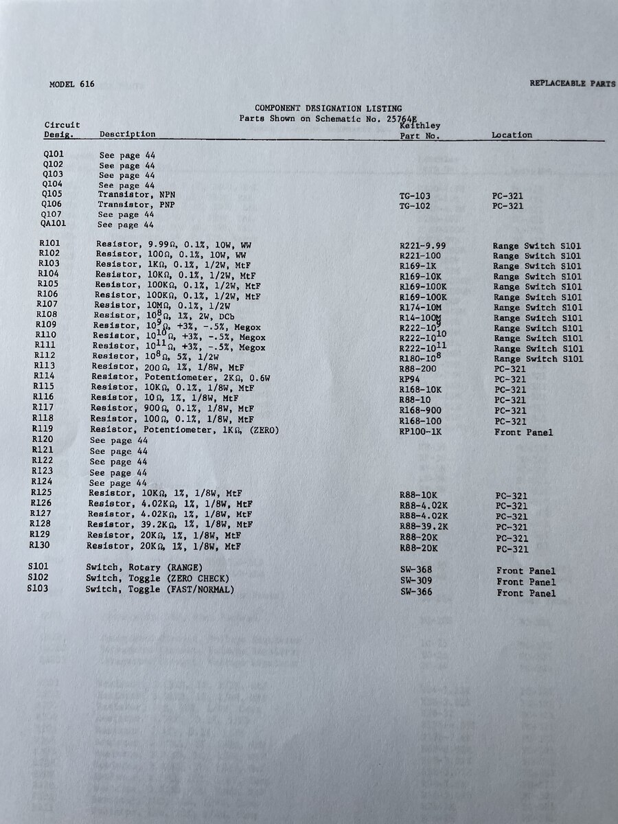
Q106 Transistor, PNP TG-102 PC-321 Q107 See page 44 QA101 See page 44 R101 Resistor, 9.99Ω, 0.1%, 1W, MW R221-9.99 Range Switch S101 R102 Resistor, 10Ω, 0.1%, 1W, MW R109-10K Range Switch S101 R103 Resistor, 100Ω, 0.1%, 1/2W, MTF R103-10K Range Switch S101 R104 Resistor, 10kΩ, 0.1%, 1/2W, MTF R104-10K Range Switch S101 R105 Resistor, 100kΩ, 0.1%, 1/2W, MTF R105-100K Range Switch S101 R106 Resistor, 10kΩ, 0.1%, 1/2W, MTF R106-10K Range Switch S101 R107 Resistor, 10kΩ, 0.1%, 1/2W, MTF R107-10K Range Switch S101 R109 Resistor, 10kΩ, 1%,
in „[S] Widerstand für Keithley 616 9.99Ohm 10W 0.1%“ · Markt · · Screenshots
-
PDF
C535A_WJN_877.pdf
logo are registered trademarks of Cree, Inc. 4 Cree 5-mm Round LED C535A-WJN CIE CHROMATICITY DIAGRAM K 00 0.3900 50 0 0 W 6 v K W 00 t W 0.3500 70 w K W 0 W r W 5 8 p u W 0K W W s 9 m K W q 0.3100 0 W 4 0 j W W 1 n W W g k y 3 Wh W 0.2700 We Wf 2 W W c Wd W a 0.2300 W b 1 W 0.1900 0.2300 0.2700 0.3100
in „Vorwiderstände für LED Matrix mit UDN2981“ · Mikrocontroller und Digitale Elektronik ·
-
PDF
Aktor_MTN647091_HW_2010_09_DE_FR_IT_NL__1_.pdf
par canal : L - F N Courant nominal : 16 A, inductif à cos M = 0,6 0 B - Ampoules : 230 V CC, 3 600 W 0-10V+ Lampes halogènes : 230 V CC, 2 500 W 7 C 4 H G Lampes halogènes max. 2 000 VA via transforma- C N BT : teurs électroniques 6 A Borne de raccordement du bus A D Lampes 230 V CC, 5 000 W, sans com
in „Merten Dimmaktor (6470 29) keine 0-10V am Ausgang“ · Analoge Elektronik und Schaltungstechnik ·
-
PDF
D100940D.pdf
heatsink TDA 16833 30 W / 3 cm 2 40 W / no heatsink 2 TDA 16834 40 W / 3 cm 40 W / no heatsink TDA 16831G 10 W / no heatsink 10 W / no heatsink TDA 16832G 20 W / 8 cm 2 20 W / no heatsink TDA 16833G 20 W / no heatsink 40 W
in „Wie startet dieses SNT ?“ · Mikrocontroller und Digitale Elektronik ·
-
PDF
U_2537_B.pdf
4.5V, Tamb=25⋅C IS 0.5 0.65 mA V S5.5V, T amb=25⋅C IS 0.6 0.8 mA Temperature dependence of –1.0 mA/K supply current Input current V = 0 V 5 I 0.6 mA I I Output voltage (active) IO= 2 mA 3 0.2 V Internal pull up resistor 3, 8 R L 80 100 120 kW Mode select voltage Output active high 3 VMS 0.5 V Mode select
in „Temic-Datenblättern“ · Analoge Elektronik und Schaltungstechnik ·
-
PDF
top200yai.pdf
MUR610CT 3.3 H 15 V VR1 R2 C3 C2 200 120 F P6KE200 1000 F 1/2 W 35 V 25 V C1 RTN 47 F D1 400 V BYV26C D3 U2 1N4148 BR1 NEC2501 L2 400 V 33 mH C4 0.1 F T1 R1 CIRCUIT PERFORMANCE: 510 R4 Line Regulation - ±0.2% 49.9 k (85-265 VAC
in „Reparatur Ladegerät DBL430-14 Überspannung“ · Analoge Elektronik und Schaltungstechnik ·
-
PDF
1N5817_1.pdf
temperature as a function of reverse voltage; function of reverse voltage (max. values); R th j-a 100 K/W. R th j-a 100 K/W. 200 MBG432 0.20 MBG437 handbook, halfpage handbook, halfpage T PR oj (W) V V ( C) V RWM RWM R δ = 0.5 δ = 0.2 150 VRWM 0.15 δ = 0.2 100 0.10 VR VRWM δ = 0.5 50 0.05 0 0 0 10 20 30
in „Suche Diode mit niedriger Durchlass-Spannung“ · Analoge Elektronik und Schaltungstechnik ·
-
PDF
Widerstaende.pdf
MΩ; 0 Ω 0.22 Ω to 22 MΩ Resistance tolerance ± 5 %; ± 1 %; ± 0.5 % Temperature coefficient ± 50 ppm/K; ± 25 ppm/K Rated dissipation, P (2) 0.4 W 0.6 W 1.0 W 70 Operating voltage, U AC/DC 200 V 350 V 500 V max. Operating temperature range(2) -55 °C to 155 °C Peak permissible film temperature2) 155 °C
in „Widerstand identifizieren“ · Analoge Elektronik und Schaltungstechnik ·
-
PDF
marantz_m-cr611_ver.1_1_-pages.pdf
4 270K E B S N 1 220K 2.2K Q421 (3216) +5V D F C G C825 R825 (2012) (2012) KN2907AS +12V_D D L802 1 2 3 4 22pF 0.2 5 D CV615280S (20122 1W 2 D822 C826 1 PC821 4 1 R422 R423 R426 R427 6 1 4 R272 UZ22B 104K EL817B
in „Schaltungsaufbau SMPS Marantz M-CR611“ · Analoge Elektronik und Schaltungstechnik ·
-
PDF
ezaehler.pdf
+ 50 = 90 Grenzstrom Nachweis: Nennstrom Primäre Wirkleistung: Nennstrom 3 x 230 V x 200 A = 138,0 kW 3 x 230 V x 250 A = 172,5 kW Der Nennstrom hat vorwiegend prüftechnische Bedeutung, da die bei der Eichung vorgeschriebenen Prüfpunkte in Prozent Summe 310,5 kW vom Nennstrom angegeben werden, z. B.
in „Bedeutung 5(32)A“ · Analoge Elektronik und Schaltungstechnik ·
-
Datei
EmulatorPIC16F84.py
) > 0x0F else 0 self.w = result & 0xFF self.update_status(self.w) elif opcode == 0x01: # ANDLW k self.w = self.w & k self.update_status(self.w) elif opcode == 0x02: # IORLW k self.w = self.w | k self.update_status(self.w)
-
PDF
Ausschaltverhalten_Ugs_Id_Uds.pdf
Ausschaltverhalten Tiefsetzstellerbetrieb (R off,hs = 0,47Ω) 400 A / 300 id(1kW) 0 200 id(1,5kW) · d 100 id(2kW) i 0 uds1kW) V / −100 uds1, 5kW) s−200 uds2kW) ud −30−20−15−10 −5 0 5 10 15 20 25 30 35 40 45 50 55 60 65 70 75 80 t / ns 4 2 0 ugs1kW) V −2 / ugs1, 5kW) g −4 u (2kW)
in „False Turn On bei Synchron Buck mit eGaN FETs“ · Analoge Elektronik und Schaltungstechnik ·
-
PDF
LTC4151.pdf
Recommended Layout for Kelvin Connection R1 0.02Ω VIN 7V to 80V VOUT VIN 8 IN OUT 1 ISO1 C6 PS9817-2 5V C7 5 LT3010-5 2 1µF R1k 8 1µF SHDNSENSE 1 VCC C4 100V GND R3 R4 7 0.1µF R12 R14 SENSE+ SENSE– 4 10k 10k 2 1k 10k GND 5 V R11 R13 IN LTC4151-2 1k 10k ADIN ADIN SDAO 8 V 1 CC ADR1 SDAI 7 2 ISO_SDA 3
in „DC Wattmeter Leistungsmesser selber bauen - Eigenbau - low cost Assembler ATmega SA56“ · Projekte & Code ·
-
PDF
clrc632.pdf
IRQ works as standard CMOS output pad. 0 indicates, that pin IRQ works as open drain output pad. 5.2.6.7 PreSet2E Name: PreSet2E Address: 0x2E Reset value: xxxxxxxx, 0xxx 7 6 5 4 3 2 1 0 x x x x x x x x Access w w w w w w w w Rights 5.2.6.8 Preset2F Name: PreSet2F Address: 0x2F Reset value: xxxxxxxx
in „SPI master/slave - schreib/lese befehle ?“ · Mikrocontroller und Digitale Elektronik ·
-
PDF
PETH-49_Labornetzteil.pdf
10k R4 R4 29 10k R4 R4 30 GL1 B250C7000 BRÜCKE2B 31 IC1 LM324N / TL074 DIL14 32 IC2 LM723 DIL14 33 IC3 LM317 TO-92C 649225 0.75 42 R1 0R39 2W R8 43 R2 560 R4 44 R3 47 R4 45 R4 1k2 R4 46 R5 100 64W 740016 2.15 47 R6 47 R4 48 R7 430k R4 49 R8 100k R4 50 R9 50K 64W 743305 2.26 51 R10 390 R4 52 R11 1k5 R4 53 R12 22k Potentiometer distrelec 742710 2.42 54 R13 11k R4 55 R14 47k R4 56 R15 10k R4 57 R16 750 R4
in „Oppermann B50“ · Mikrocontroller und Digitale Elektronik ·
-
PDF
58740807_protel_schematic.pdf
R90 R71 AGND 2 OUT1 3 GND R2 10k 6 TLC272 249k 464k v 4 1 R76 4 R89 I1 1k 464R 5 POT R3 10k 12 6 14 X0 C 13 R26 AGND 7 15 X1 V X 1M82 AGND Stecker 7pol. R1 11 X2 R59 Erkennung 25W, 50W, 80W, 150W 10k EXTERN4 X3 LEISTUNG
in „Suche Service Manual oder Schaltplan für Weller WMD-3“ · Mechanik, Gehäuse, Werkzeug ·
-
PDF
1683356.pdf
of disconnection Micro-disconnection Dielectric strength V AC/kV (1.2/50 μs) 1,000/1.5 Conducted disturbance immunity Burst (5...50)ns, 5 kHz, on A1 - A2 EN 61000-4-4 level 4 (4 kV) Surge (1.2/50 μs) on A1 - A2 (differential mode) EN 61000-4-5 level 3 (2 kV) Other
in „Suche RC-Glied für Finder Relais“ · Mikrocontroller und Digitale Elektronik ·
-
PDF
Quarzfilter_Rev2b.pdf
S)-EXP(-S))/2 1330 W=LOG(E+SQR(E*E-1))/NP 1340 W=(EXP(W)+EXP(-W))/2 1350 D=S/(2*SIN(X)*W) 1360 FOR C=1 TO NP-1 1370 K(C)=SQR((S*S+SIN(C*2*X)^2)/(4*SIN((2*C-1)*X)*SIN((2*C+1)*X)))/W 1380 NEXT C 1390 '--- Berechnung der max. Bandbreite --- 1400 K=0 1410 IF NP=2 THEN K=K(1) 1420 K=K+K(1)+K(2) 1430 T=FP-FS 1440 BX=T*(K-SQR(K*K-1)) 1450 PRINT"Bandbreite in kHz" 1460 PRINT"(max.:";BX/1000;"kHz) "; 1470 INPUT BW :BW=BW*1000 1480 IF BW<BX THEN 1500
in „Schmalbandiges LC-Filter, praktischer Aufbau“ · HF, Funk und Felder ·
-
PDF
Quarzfilter_Rev2b.pdf
S)-EXP(-S))/2 1330 W=LOG(E+SQR(E*E-1))/NP 1340 W=(EXP(W)+EXP(-W))/2 1350 D=S/(2*SIN(X)*W) 1360 FOR C=1 TO NP-1 1370 K(C)=SQR((S*S+SIN(C*2*X)^2)/(4*SIN((2*C-1)*X)*SIN((2*C+1)*X)))/W 1380 NEXT C 1390 '--- Berechnung der max. Bandbreite --- 1400 K=0 1410 IF NP=2 THEN K=K(1) 1420 K=K+K(1)+K(2) 1430 T=FP-FS 1440 BX=T*(K-SQR(K*K-1)) 1450 PRINT"Bandbreite in kHz" 1460 PRINT"(max.:";BX/1000;"kHz) "; 1470 INPUT BW :BW=BW*1000 1480 IF BW<BX THEN 1500
in „Messen von Quarz-Parametern - Probleme“ · HF, Funk und Felder ·
-
PDF
A4915-Demo-Board-Schematic.pdf
u F k R 4 R 5 . 4 k U B N 2 N G G O R A P C N N U W K BL R E D D T 1 E E D G G U 5 0 1 9 3 8 6 7 2 5 / N N I L V C D D N T F H H H T B E D S D A B C A D R N R E 1 L A K B E F T A D E L D 4 D 9 E VDD 25 D 2
in „A4915 Problematik“ · Analoge Elektronik und Schaltungstechnik ·
-
PDF
tafelwerk1-gedreht.pdf
2 maximal P P aus= a 2 zweite Harmonische 2 × Ia− Ia1 I a5 k2= Klirrfaktor 2 × (Ia5 I a1 dritte Harmonische 2 × Ia4 I a2I +a5 a1 k 3 3 × (Ia5 I a1 gesamt 2 2 K = k 2 + k3 Zusammenhänge Je größer
in „Röhrenverstärker Berechnen“ · Analoge Elektronik und Schaltungstechnik ·
-
PDF
ver968de.pdf
L1 L2 L3 L1 L2 L3 I ULN LN ULN LN V1 U2 V1 U2 V2 U1 V2 U1 W2 W2 W2 W1 U LN= √3 • U W ILN= IW U LN= U W LN = √3 • W L1 L2 L3 L1 L2 L3 LN U LN LN ULN U1 V1 W1 U1 V1 W1 W2 U2 V2 W2 U2 V2 Mit seiner Spannungsangabe
in „Drehstromkompressor an 230V via FU“ · Analoge Elektronik und Schaltungstechnik ·
-
PDF
LT1161.pdf
Switch with Isolated Inputs and Fault Output 24V NEC PS2501-4 1 + 20 5.1k GND V + 1 F + 2 19 50 F T1 DS1 0.015 50V 5.1k 3 IN1 G1 18 RFD16N05 LOAD 1 F + 4 17 0.015 #1 T2 DS2 INPUTS 5 16 100k 5.1k IN2 G2 RFD16N05 1 F + 6 LT1161 15 LOAD T3 DS3 0.015 #2 7 IN3 G3 14 RFD16N05 100k 5.1k LOAD 1 F + 8 13 0.015 #3 T4 DS4 9 12 100k IN4 G4 RFD16N05 10 11 LOAD GND V+ #4 24V MM74HC266A 100k 18k 2N3904 1161 TA02 5.6V 1N5994B 4N28 FAULT 5.1k 0.1 F OUTPUT 2k Information furnished by Linear Technology
in „Erfahrungen mit LT1161“ · Mikrocontroller und Digitale Elektronik ·
-
PDF
sn761678b.pdf
amplifier output Figure 15 XTAL 15 4-MHz crystal oscillator input Figure 16 150 kW 19 18 50 kW S0159-01 S0133-03 Figure 1. Figure 2. 3 Submit Documentation Feedback SN761678B TVTUNERIC SLES185–JUNE 2006 www.ti.com 23 20 p 20 p 24 20 21 22 50 kW 28 S0138-02 Figure 3. Figure 4. 12 13
in „Infos zu TV-Tunern gesucht“ · Analoge Elektronik und Schaltungstechnik ·
-
PDF
FT_1981_Heft_05_OCR.pdf
(1980) S. W 95-W 103. Tel. (071 43) 3750 i 182 Funk-Technik 36 (1981), Heft 5 i Fachliche Bildung FT-Lehrgang M : o c o m p u t e ri nd e r H e r h a l t u n g s e l e k t r o n i k 1 1 .IF o Bg e:M ikro c o m p
in „[VS] verschenke Taststift“ · Markt ·
-
PDF
User_Guide_Timer.pdf
L▯NO▯P▯ QSU H▯ **@.'252.$*58&:%&3*5&13&%2.&$3& '0**6133915&0131+&80:6++02'+2&*'0C 4.315&12&<53+3*1$&@013@&*1.G&+&: J▯K ▯▯▯ ▯▯▯▯W▯▯▯▯YZ"M ?=\][▯<?=[][^<3@?F[\A>▯A&7&*%8%&.+ &1@#%')456&082&1%+&&9.':_5&&&7&<15 %&() %2&*'&@30+;32013<A&.6'.& @.1+; +.&0%8'&&*&*: ▯▯ ▯▯▯▯ ▯▯▯▯▯ ▯ ▯ ▯▯▯▯▯▯▯▯▯ ▯▯▯▯▯ ▯▯▯▯ ▯▯ "2% 6K PRTUWY A**<+ (0+ / + ▯▯ ) .A \ )) ▯GH."2% 0C3% .A= 15& <;-) A \ )▯ ▯E'F /!2 2$% = */ \ ▯) ▯ *2.AI? .A = ▯▯▯O ▯▯▯M ▯▯▯Z ▯▯▯[ ▯▯▯▯ *+ /+ !96 ,7 * * 'A )) $&2 /32 ▯▯ ) 'B )▯ ) ?@0 ▯) A =' ."% 6K *56
in „Interrupts / Timer/ MSP430F449“ · Mikrocontroller und Digitale Elektronik ·
-
PDF
edip240-7.pdf
MSB (Bit7) wird zuerst gesendet. h = 1: LSB (Bit0) wird zuerst gesendet. l e . CPOL(ClockPOLariy): W r = 0: Ruhezustand von SCK LOW. ü = 1: Ruhezustand von SCK HIGH. e n h CPHA(ClockPHAse): m e = 0: Übernahme bei 1. Flanke k = 1: Übernahme bei 2. Flanke e n H a t n g ü r r c k e l r n d A p l a i n
in „BMP mit T6963“ · Mikrocontroller und Digitale Elektronik ·
-
PDF
LT3092fb.pdf
5V, V SET = 0V, OUT = –0.1V l 200 300 mA Reference Current RMS Output Noise (Note 5) 10Hz ≤ f ≤ 100kHz 0.7 nA RMS Ripple Rejection f = 120Hz, RIPPLE = 0.5VP-P LOAD = 0.1A, 90 dB CSET = 0.1μF, OUT= 2.2μF f = 10kHz 75 dB f = 1MHz 20 dB Thermal Regulation ISET 10ms Pulse 0.003 %/W Note 1: Stresses beyond
in „Konstantstromquelle LT3092 - Widerstandswahl“ · Analoge Elektronik und Schaltungstechnik ·
-
PDF
BTT_SKR_V1.4-SCH.pdf
4 TRST / 2 / / E . / / E E 6 / A M / S S S I O VSS 72 GND 1 NPWR R21 1K E1DET 3.3V FB1 Uc3.3V SWDCLK 5 TCK/SWDCLK 0 0 1 1 . P 1 .1 4 E 1 . K K L W / K / / VDD 71 Uc3.3V C10 J7 2 LED U2 P0.26 6 P0.26/AD0.3/AOUT/
in „Induktiven Sensor (6-36V) an Microcontroller/Mainboard anschließen“ · Mikrocontroller und Digitale Elektronik ·
-
PDF
BTT_SKR_V1.4SCH.pdf
4 TRST / 2 / / E . / / E E 6 / A M / S S S I O VSS 72 GND 1 NPWR R21 1K E1DET 3.3V FB1 Uc3.3V SWDCLK 5 TCK/SWDCLK 0 0 1 1 . P 1 .1 4 E 1 . K K L W / K / / VDD 71 Uc3.3V C10 J7 2 LED U2 P0.26 6 P0.26/AD0.3/AOUT/
in „3D-Drucker, Mainboard-Lüfteranschluss erweitern“ · Mikrocontroller und Digitale Elektronik ·
-
PDF
AD1937.pdf
0x0E) Bit Value Function Description 0 0 Normal Power-down 1 Power down 1 0 Off High-pass filter 1 On 2 0 Unmute ADC1L mute 1 Mute 3 0 Unmute ADC1R mute 1 Mute 4 0 Unmute ADC2L mute 1 Mute 5 0 Unmute ADC2R mute 1 Mute 7:6 00 32 kHz/44.1 kHz/48 kHz Output sample rate 01 64 kHz/88.2 kHz/96 kHz 10 128 kHz
in „Aktives Filter simulieren“ · Analoge Elektronik und Schaltungstechnik ·
-
PDF
Spec_Inkontinenzsensor_ATtiny461A.pdf
.. + xxx + R/W 1110 0x70 112 0xE0 224 .. + xxx + R/W 0x78 120 0xF0 240 1111 .. + xxx + R/W reserviert ATtiny261 analog: /A3 0 1 0 A2 A1 A0 R/W ATtiny461A: 0 1 0 1 A2 A1 A0 R/W ATtiny261 binär: /A3 0 1 1 A2 A1 A0 R/
-
PDF
SPS9540_KM_G_011017.pdf
1 k 1 1 0 W 2 5 1 1 1 3 1 1 R W D R D R 1 3 2 1 3 8 0 1 R 1 1 1 T 9 D S s 2 1 3 1 E 3 0 1 . 3 p 0 P c a tt a W2 8 0 F T c 033 6 2 311R 0 tt a W2 1 033 C 321R tt a W2 72R G G 0 5 4 0 121R + - T A 1 A 8414N1
in „*Netzteil die ZWEITE*“ · Mikrocontroller und Digitale Elektronik ·
-
PDF
183571-da-01-en-LCD-Inverter_12V__1_.pdf
(kHz) f 25 30 35 5±5% –10 to +60 45 to 75 Open circuit Erms(V) Vopen 800 900 — 5±5% –10 to +60 output voltage Output power (W) Pout — — 2.25 5±5% –10 to +60 — Iout1 4.5 5 5.5 5±1% 23±5 60 Iout2 4.5 5 5.5
in „Einfacher Low Cost LCD Controller für 320x240 LCD im Textmodus“ · Projekte & Code ·
-
PDF
EA434_CXAL10.pdf
(kHz) f 25 30 35 5±5% –10 to +60 45 to 75 Open circuit Erms(V) Vopen 800 900 — 5±5% –10 to +60 output voltage Output power (W) Pout — — 2.25 5±5% –10 to +60 — Iout1 4.5 5 5.5 5±1% 23±5 60 Iout2 4.5 5 5.5
in „CCFL Displaybeleuchtung steuern“ · Mikrocontroller und Digitale Elektronik ·
-
PDF
HN_PDTC114E_SER.pdf
Max Unit R th(j-a) thermal resistance from junction in free air to ambient PDTC114EE (SOT416) [1][2]- - 830 K/W PDTC114EM (SOT883) [2][3]- - 500 K/W [1] PDTC114ET (SOT23) - - 500 K/W PDTC114EU (SOT323) [1] - - 625 K/W [1] Device mounted on an FR4 PCB, single-sided copper, tin-plated and standard footprint
in „AEG Lavatherm IH67680IH schaltet sporadisch ab“ · Analoge Elektronik und Schaltungstechnik ·
-
PDF
problem4051.pdf
1 2 3 4 5 6 K K K K K K K K R 0 R 0 R 0 R 0 R 0 R 0 R 0 R 0 R R R R R R R R 3 1 3 1 3 1 3 1 3 1 3 1 3 1 3 1 A A h S h S h S h S h S h S h S h S i i i i i i i i w w w w w w w w s s s s s s s s 4 2 4 2 4 2
in „was passiert in meiner schaltung? oO“ · Analoge Elektronik und Schaltungstechnik ·
-
PDF
proline-3600-amplifier-schematic.pdf
R141 R142 R143 R144 R145 R146 U T159 1 1 0 T S R 0 1 8 0 6 K D 7X2.2 1 0 1 K V R 1 1 0 4 1 7 0 4 . 1 T157 0 K T 2 6 R122 D 4 D N 0 2 1 6 7 7 5 1 . 2 5 8 K 1 1 0 0 1 0 T V 9 C115 7 3 1 W 3 4 7 0 4 5 6 7 8 9 0 9 R 4 1 . 2.2K R 1 R 1 2 3 1 6 R 3 R / R 3 R 1 1 1 1
in „Audio Verstärker an Bauerndrehstrom“ · Analoge Elektronik und Schaltungstechnik ·
-
PDF
proline-3600-amplifier-schematic.pdf
R141 R142 R143 R144 R145 R146 U T159 1 1 0 T S R 0 1 8 0 6 K D 7X2.2 1 0 1 K V R 1 1 0 4 1 7 0 4 . 1 T157 0 K T 2 6 R122 D 4 D N 0 2 1 6 7 7 5 1 . 2 5 8 K 1 1 0 0 1 0 T V 9 C115 7 3 1 W 3 4 7 0 4 5 6 7 8 9 0 9 R 4 1 . 2.2K R 1 R 1 2 3 1 6 R 3 R / R 3 R 1 1 1 1
in „Dimensionierung eines Ringkerntransformators“ · Analoge Elektronik und Schaltungstechnik ·
-
PDF
proline-3600-amplifier-schematic.pdf
R141 R142 R143 R144 R145 R146 U T159 1 1 0 T S R 0 1 8 0 6 K D 7X2.2 1 0 1 K V R 1 1 0 4 1 7 0 4 . 1 T157 0 K T 2 6 R122 D 4 D N 0 2 1 6 7 7 5 1 . 2 5 8 K 1 1 0 0 1 0 T V 9 C115 7 3 1 W 3 4 7 0 4 5 6 7 8 9 0 9 R 4 1 . 2.2K R 1 R 1 2 3 1 6 R 3 R / R 3 R 1 1 1 1
in „PA Endstufe Kondensatoren durch größere ersetzen“ · Analoge Elektronik und Schaltungstechnik ·
-
PDF
lm324_Original.pdf
input voltage range VCC= 5 V to MAX V Full range 0 to 0 to V CC– 2 VCC– 2 RL= 2 kΩ 25°C VCC – 1.5 VCC – 1.5 VOH High-level output voltage RL= 2 kΩ Full range 26 26 V VCC= MAX RL≥ 10 kΩ Full range 27 28 27 28 VOL Low-level output voltage RL≤ 10 kΩ Full range 5 20 5 20
in „gutes Übersetzungsprogramm für Datenblätter gesucht“ · Offtopic ·
-
PDF
W2000L_reference_manual.pdf
mode. The trigger does handle the signal capture buffer and does provide the roll mode capability. 2.2.3 Capture Buffer The signal capture buffer is limited to 32 kB by the FPGA. It could be used for 32 kS for 1 channel with 8 bit downto to 8 kS for 2 channels with 16 bit. The maximum roll mode sampling
in „made from scratch Firmware für Wittig/Welec Oszilloskop W20xxA“ · Mikrocontroller und Digitale Elektronik ·
-
PDF
Auslegung.pdf
/W Thermischer Widerstad des Kühlkörpers (aus Datenblatt) R thJC 5,3 K/W Thermischer Widerstad des Übergangs Sperrschicht - Gehäuse (aus Datenblatt) R thCS 5,3 K/W Thermischer Widerstad des Übergangs Gehäuse
in „30A Endstufe“ · Analoge Elektronik und Schaltungstechnik ·
-
Datei
KthElement.pas
L2 IF L1[OG1] < L2[UG2] then begin k := OG2-k; IF k < 0 then begin k := k+OG1; result := L1[k]; end else result := L2[k]; exit; end; //alle Elemente aus L2 < Elemente aus L1 IF L2[OG1] < L1[UG2] then begin
-
PDF
LiIonCharger_BQ2057C_extMOSFETorPNP.pdf
BQ2057C V = Z ´I (Z) (PACK) (REG) V(Z)= 0.1´0.5 V(Z)= 50 mV (16) V(Z) V(COMP) = G(COMP) V = 0.05 (COMP) 2.2 V(COMP) = 22.7 mV Let RCOMP2 =10 kW (17) Copyright © 2022 Texas Instruments Incorporated Submit Document Feedback21 Product Folder Links: BQ2057 BQ2057C BQ2057T BQ2057W BQ2057, BQ2057C, BQ2057T, BQ2057W SLUS025G – MAY 2001 – REVISED DECEMBER 2022 www.ti.com R COMP2 ´(V(SNS)- V(COMP)) R COMP1 = V (COMP) (105 mV 2-.7 mV ) R =10k ´ COMP1 22.7 mV R =36.25 kW COMP1 (18) Use the closest standard value (36.0 kΩ) COMP1 . 10.2 Typical Application RSNS Q1 0.2Ω FZT788B PACK
in „LiIon Charger BQ2057 - wozu dieser Widerstand?“ · Analoge Elektronik und Schaltungstechnik ·
-
PDF
1MA98_4E_dB_or_not_dB.pdf
W/m or m2)m . The corresponding logarithmic units are dB(W/m ) and dB(mW/m . S 10lg S dB(W/m ) 2 1W/m 2 S S 10lg 2 dBm/m 2 1mW/m Electric field strength E is measured in V/m or µV/
in „Wie stehen dBm und Volt zueinander?“ · HF, Funk und Felder ·