-
Thread
Fenster auf Erkennung per Funk, welches System
:23,"last_seen":"2023-07-25T12:50:01.316Z","linkquality":91,"power":773,"power_outage_count":426,"side":5,"voltage":3025} [/code] Man beachte die "action_angle"-Angabe - man erfährt nicht nur, dass der Würfel im Uhrzeigersinn gedreht wurde, sondern auch, um wieviel Grad.
-
Thread
Temperaturmessung Gewächshaus. BMS Problem.
Knaller, selbst die hochprofessionellen Equipments werden mit Bleiklötzen gepuffert. In Island. side note: Panasonic wollte offenbar nicht für die beiläufige Werbung zahlen, deshalb hatte man den Firmennamen auf den Akkus ausgepixelt. warum Blei? wahrscheinlich deswegen: >> Das Problem ist
-
Thread
Karte Clonen Gesperrt
suchen, leider ohne Erfolg. Es läuft eine Schleife die unendlich scheint. Mifare Classic 'Dark-Side' Attack to reover at least 1 key for card where NO keys are known. Key A sectors: Key B sectors:Attack: 3-A diff Nt:0 auths:0 Attack: 3-A diff Nt:1 auths:1 Attack: 3-A diff Nt:2 auths:2
-
 Bild
Bild
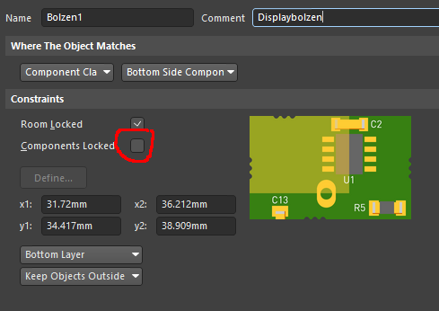
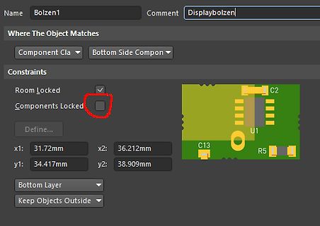
Screenshot einer CAD-Software für Leiterplatten-Layout
Name: Bolzen1 Comment: Displaybolzen Where The Object Matches Component Cla Bottom Side Compon Constraints Room Locked Components Locked Define... x1: 31.72mm x2: 36.212mm y1: 34.417mm y2: 38.909mm C2 U1 C13 R5 Bottom Layer Keep Objects Outside
-
Thread
BLDC mittels ESC ansteuerung
die 6 parallelen Flyback Dioden von Drain zu Source. Habe jetzt aber ein Problem das die 3 High Side Mosfets ziemlich schnell Heiß werden wenn der Motor läuft. Als boostrap Kondensator habe ich jetzt einen 100nF Keramik gewählt. Habe die Phasen auch als Phase A, -B, -C umbenannt. Dazu habe ich noch
-
Thread
Functional Safety Open Source
wirklich Anforderungen an einen Digital Eingang sind der über Software in den Dual CPUs dann High-Side Treiber schaltet welches ein Ventil zum Beispiel ansteuert. Aus dem Beispiel sieht man schon, dass dies natürlich jetzt schon wieder spezifisch ist und man da natürlich die ganze Kette betrachten
-
 Bild
Bild
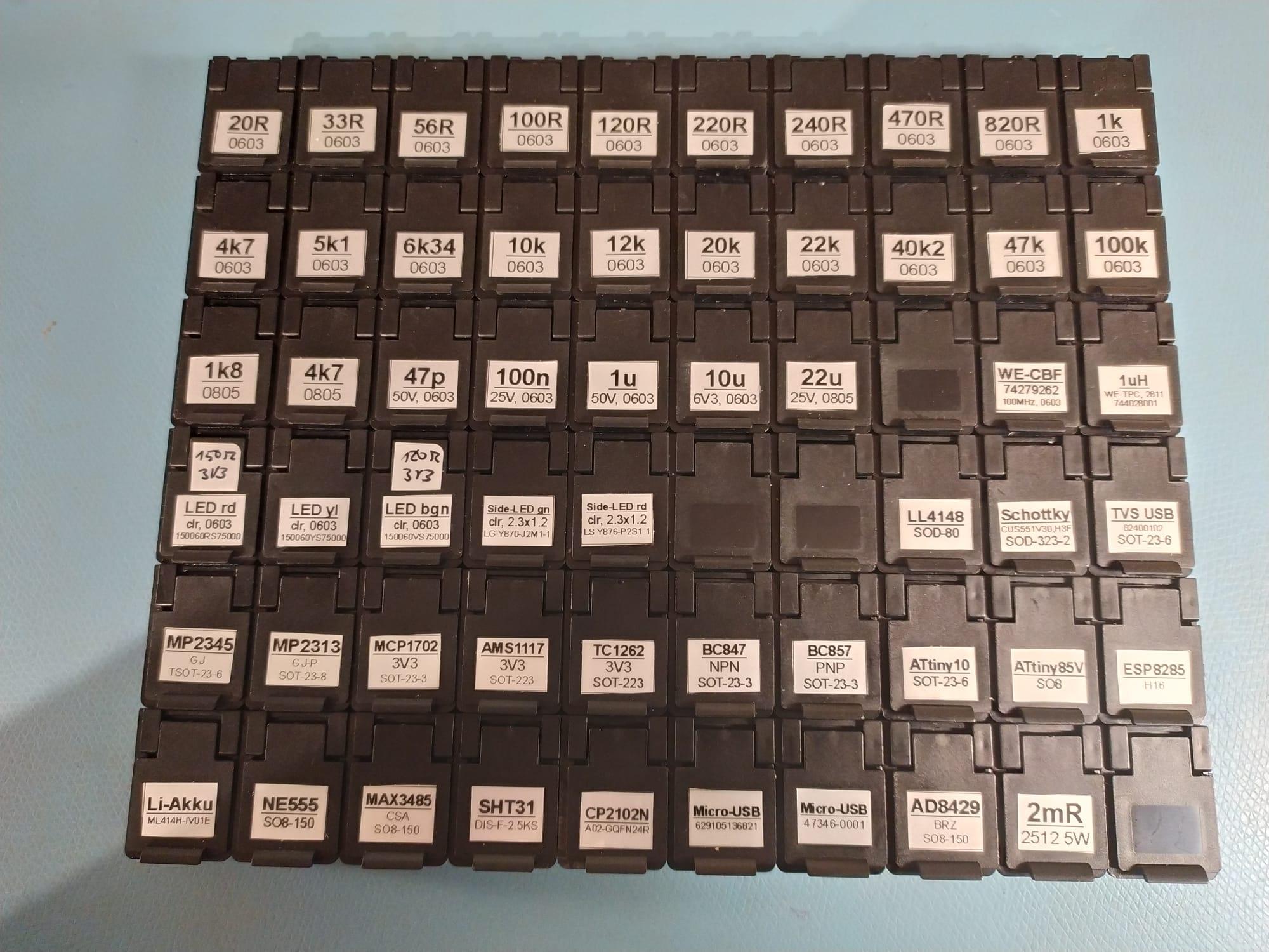
Sortiment an elektronischen Bauteilen in Kunststoffboxen
100n 25V 0603, 1u 6V3 0603, 10u 25V 0603, 22u 0805, 15n2 3V2, 12n2 3T2, LED rd, LED vi, LED bgn, side-LED an, side-LED dr, LL4148, Schottky, TVS USB, MP2345, MP2313, MCP1702, AMS1117, TC1262, BC847, BC857, ATtiny10, ATtiny85V, ESP8285, Li-Akku, NE555, MAX3485, SHT31, CP2102N, Micro-USB, Micro-USB, AD8429

-
 Bild
Bild
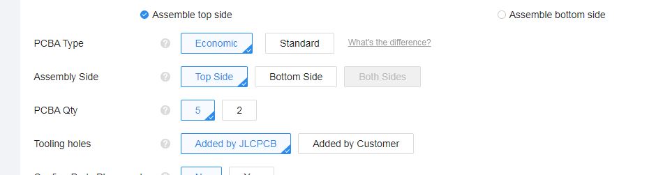
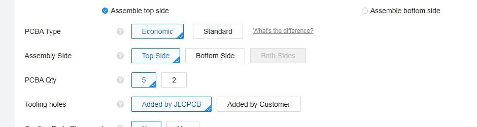
Konfigurationsoptionen für eine PCBA-Bestellung
Assemble top side Assemble bottom side PCBA Type Economic Standard What's the difference? Assembly Side Top Side Bottom Side Both Sides PCBA Qty 5 2 Tooling holes Added by JLCPCB Added by Customer
-
Thread
ESP 32 (Mikrokontroller) Mittels FlipFlop oder Transistor nur bei Tastendruck an- bzw ausschalten
Eine "High side switch" ist eine moglichkeit. Mit ein taster signal wird er "ein" geschaltet, danach ubernimmt den ESP32 mit eine Ausgang das Signal, so das den "high side switch" eingeschaltet bleibt so lange wie
-
Artikel
Reichelt-Wishlist
Lambdasonden-IC) | | | DS1616 von Dallas Datalogger-IC * DTMF-Dekoder-Enkoder (8870, 8880) | | | | | | High Side Current Sense ICs wie MAX4172,LT6105 | * IRS2092 Class-D Audio Driver IC * ISD 2560 -> SOIC Gehäuse (Sprachaufnahme IC) | | ITS4141N o. BTS4141N Smart High-Side Power Switch (z. B. bestens für 24V geeignet
(SMD Optokoppler) | TLP250 (Opto MOSFET Gate Treiber auch für High Side) * TORX 178 Fiberoptik-Receiver | TOTX177PL und TORX177PL (Fiberoptik-Transmitter) als Ersatz für TOTX173 und TORX173 (zwar anderes Footprint, aber dafür auch kleiner und günstiger) TSOP 1140 Infrarot-Receiver
-
Thread
C Funktionsaufruf mit 2D Array
; ic_register pwm; ic_register pwmb; ic_register sctrl; ic_register sctrlb; uint8_t sid[6]; bool isospi_reverse; pec_counter crc_count; register_cfg ic_reg; long system_open_wire; } cell_asic; [/c] und weiter ins Kaninchenloch: [c] typedef struct { uint8_t cell_channels
-
 Bild
Bild
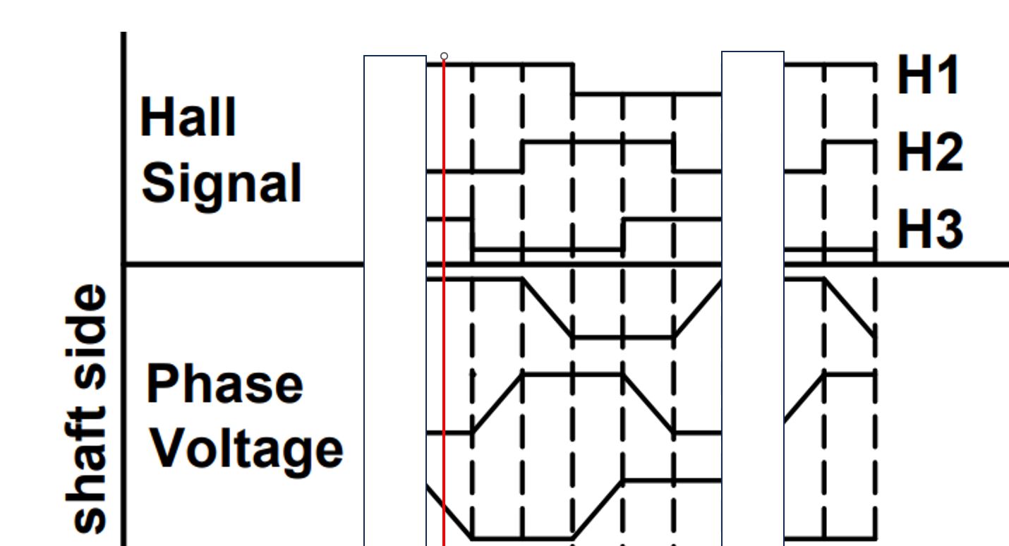
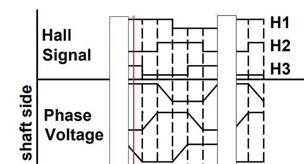
Diagramm von Hall-Signalen und Phasen-Spannung
Hall Signal H1 H2 H3 shaft side Phase Voltage
-
Thread
Auswahl Einbaukupplung und Kabelstecker für LED Streifen
www.reichelt.de//446/index.html?ACTION=446&SEARCH=lutronic&START=0&OFFSET=16&LA=2&nbc=1&q=lutronic&SID=93b7470fb5566855428356be60b5fbbf0acc03076c9f3abb220db
2&GROUPID=7505&SEARCH=%2A&START=0&OFFSET=100&CCOUNTRY=459&LANGUAGE=de&CCOUNTRY=459&LANGUAGE=de&r=1&SID=925269006a5e50254d025c7dc663fa2c308820023b3a41e7453bc
-
Thread
Totes Mainboard
Das hängt davon ab, ob der Schalttransistor als Low-Side Schalter oder High-Side Schalter verwendet wird.
PL8502 (die Rechte auf dem Bild) mit Heißluft ausgelötet habe, hatten die beiden zugehörigen Low-Side Mosfets PQ8508 und PQ8509 keinen Durchgang mehr. Innerhalb der Schaltung haben beide 257 Ohm. (im Vergleich zu den anderen beiden Low-Side Mosfets recht niederohmig.) Der High-Side Mosfet PQ8507 hatte
-
Thread
Was ist das?
xx.fbcdn.net/v/t39.30808-6/305573660_472704598235591_4568688771027613497_n.jpg?_nc_cat=102&ccb=1-7&_nc_sid=e3f864&_nc_ohc=_nvbvDlJ38UAX8RjoIu&_nc_ht=scontent-muc2-1.xx&oh=00_AfAPOZMJv0o8q_tozY1XKCOxT6HUjek5igS0DwZlINiptg&oe=64A374F0
-
Thread
Microsoft will Windows 11 komplett in die Cloud verlagern
". Ohne den Play-Store geht in Android nichts. Mit der nächsten Android-Version möchte Google das Side-Loading ganz abschalten.
René H. schrieb im Beitrag #7447586: > Mit der nächsten Android-Version möchte Google das Side-Loading ganz > abschalten. Soso. Nachdem Apple gerade per Digital Markets Act gezwungen wird, es mindestens in der EU freizugeben. ;-) Sachte. Google hat nicht vor, Löcher im EU-Haushalt zu
-
Thread
Arduino Uno R4 im Handel erhältlich
Controller irgendwelche Leistungssachen schalten soll, werden da immer gleich sowas wie fertige High-Side Switche oder ähnliches angeschlossen? Ein direkt angeschlossenen Mosfet kann man ja mit üblichen 4mA nicht vernünftig schnell schalten. Das ist schon mit 20mA grenzwertig nur reicht das fürs "basteln
-
Thread
ESP32 3.3V Logik Level Mosfet
zuschalten, weder mit PNP noch PMOSFET, man braucht zwingend einen weiteren Transistor oder einen high side Switch oder ähnlich modernes wie https://www.mouser.de/ProductDetail/Texas-Instruments/TPS22950CDDCR . Gibt es auch mit Drahtenden für Wurstfinger https://www.mouser.de/ProductDetail/Texas-Instruments
Widerstand mehr, muss nicht unbedingt sein. Stimmt, ein FPF2110 reicht (oder irgendein 5V-High Side Switch). 1 Bauteil insgesamt. Normal würde man noch einen Widerstand spendieren, damit der sicher abschaltet, wenn der uC im Reset hängt. Aber das ist hier wohl sch*egal ;)
-
 Bild
Bild
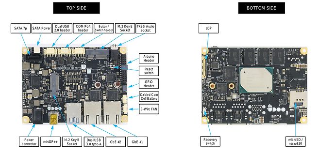
Vorder- und Rückseite einer Single Board Computer Platine
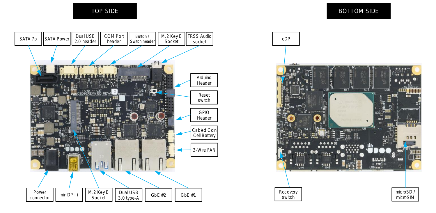
TOP SIDE BOTTOM SIDE SATA 7p SATA Power Dual USB 2.0 header COM Port header Button / Switch header M.2 Key E Socket TRSS Audio socket Arduino Header Reset switch GPIO Header Cabled Coin Cell Battery 3-Wire FAN
-
 Bild
Bild
Tabelle der PIO Instruction Encoding Bitbelegung
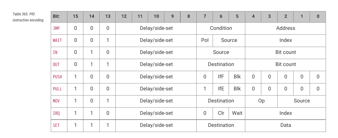
Table 365. PIO instruction encoding Bit: 15 14 13 12 11 10 9 8 7 6 5 4 3 2 1 0 JMP 0 0 0 Delay/side-set Condition Address WAIT 0 0 1 Delay/side-set Pol Source Index IN 0 1 0 Delay/side-set Source Bit count OUT 0 1 1 Delay/side-set Destination Bit count PUSH 1 0 0 Delay/side-set 0 IfF Blk 0 0 0 PULL 1 0 0 Delay/side-set 1 IfE Blk 0 0 0 MOV 1 0 1 Delay/side-set Destination Op Source IRQ 1 1 0 Delay/side-set 0 Clr Wait Index SET 1 1 1 Delay/side-set Destination Data
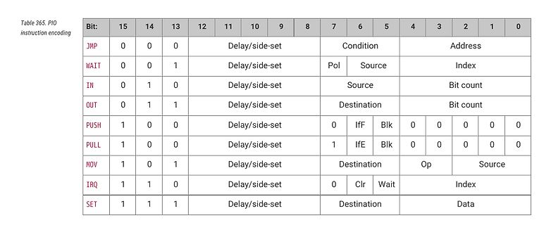
-
 Bild
Bild
Spezifikationsblatt einer HP-520S Druckmaschine
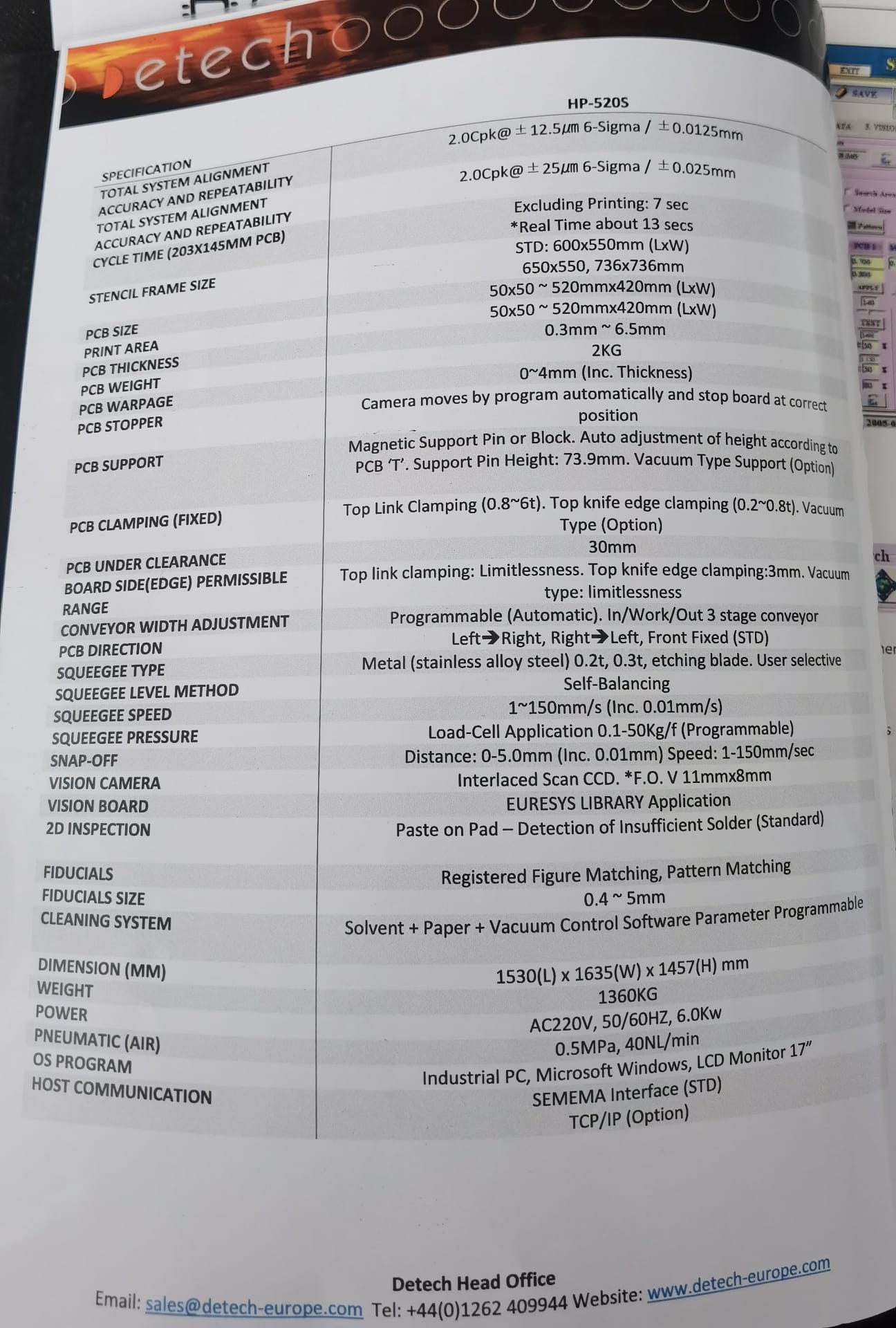
THICKNESS PCB WEIGHT PCB WARPAGE PCB STOPPER PCB SUPPORT PCB CLAMPING (FIXED) PCB UNDER CLEARANCE BOARD SIDE (EDGE) RANGE CONVEYOR WIDTH ADJUSTMENT PCB DIRECTION SQUEEGEE TYPE SQUEEGEE LEVEL METHOD SQUEEGEE SPEED SQUEEGEE PRESSURE SNAP-OFF VISION CAMERA VISION BOARD 2D INSPECTION FIDUCIALS FIDUCIALS SIZE CLEANING
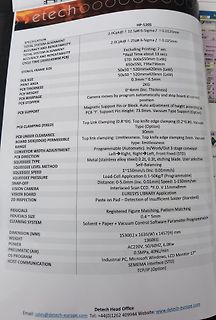
-
Thread
Fritzing 1.0 – nur für zahlende Downloader
unterscheidet. Das neue Format ist folgendermaßen aufgebaut: [c] 'RefDes, Value, Package, X, Y, Rotation, Side, Mount'. [/c] ### Simulator ist nun offiziell Fritzing brachte seit einiger Zeit einen auf SPICE basierenden Schaltungssimulator mit – in Version 1.0 ist er nun ein offiziell unterstütztes Feature
-
Thread
OceanGate Titanic U-Boot
weiterliest: “Some of the ballast is abandoned construction pipes that > are sitting on shelves on the side of the thing, and the way you detach > the ballast is you get everybody on board to lean into one side of the > sub and they roll off.” Warum kompliziert, wenn es auch einfach geht! Nur was ist
#7439228: > “Some of the ballast is abandoned construction pipes that > are sitting on shelves on the side of the thing, and the way you detach > the ballast is you get everybody on board to lean into one side of the > sub and they roll off.” Was sich sehr schwer gestaltet wenn man auf Grund liegt oder
-
Thread
Pin Belegung Gardena Bodenfeuchtesensor 1867-20 gesucht
Ende des Aufheizvorgangs doch über die Stromaufnahme detektieren. Es reicht dazu aber ein 10 Ohm low-side shunt. Ich habe meine Erkenntnisse dazu auf meinem o.g. Wiki dokumentiert. LG, Sebastian
-
 Bild
Bild
Metallblock auf Lochplatte
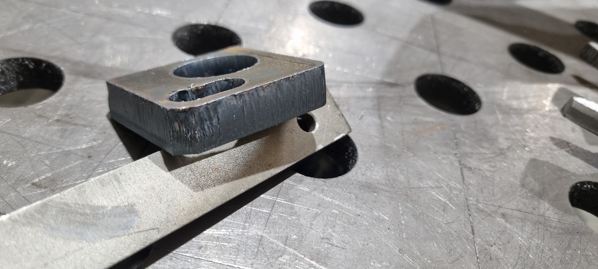
side.jpg
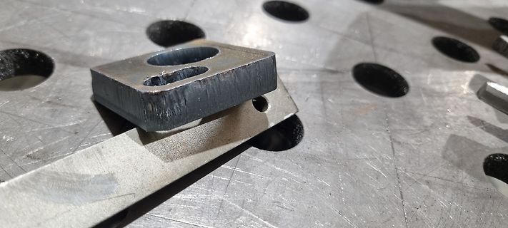
-
Thread
Stannol Industa MPL-4010, Fehler F01
Kolben aus der Ersa-Serie. http://www.movo-online.de/index.php?cat=KAT20&lang=DEU&product=P50070-AA&sid324EC0293F5F4A4B8C3E41A64533477D=8bf6aef99a0f6da768306a608426c8d0 Es gibt leider keinen Support mehr. Was könnte die Fehlermeldung F01 bedeuten? Die Meldung kommt auch ohne angeschlossenen Lötkolben
-
Thread
Starker Hubmagnet 12V Empfehlung
aber ohne Datenblatt https://heschen.com/de/products/hechen-solenoid-electromagnet-hs-1240s?_pos=32&_sid=3eaa74d76&_ss=r Der 1040 Hub ist 10mm, gefordert waren 17mm. Ich gehe jetzt aus vom H. H. schrieb im Beitrag #7435421: https://www.mikrocontroller.net/attachment/601560/db-hubmagnete-HMF-3830d
-
Thread
Rust Problem Compile mit Fehler
- Has serialize instruction. seses - Prevent speculative execution side channel timing attacks by inserting a speculation barrier before memory reads, memory writes, and conditional branches. Implies LVI Control Flow integrity.. sgx - Enable
-
Thread
Bauteil explodiert
//446/index.html?ACTION=446&SEARCH=Entstördrossel&START=0&OFFSET=16&LA=446&SORT=-rank&SHOW=1&nbc=1&SID=93e9c971e89667194bef94572e6da2c65cb8b46c15781e2ba9327
-
Thread
Wieso ist bei diesem RC-Motorregler das +Kabel blau?
Der Motor wird Low-Side mit einem MOSFET geschaltet, also ist das der Minuspol des Motors.
Mario M. schrieb im Beitrag #7434361: > Der Motor wird Low-Side mit einem MOSFET geschaltet, also ist das der > Minuspol des Motors. Danke. Wir leben um zu lernen. Ich bin kein Profi-RC-Bastler sondern just for fun. Dann nehme ich mal an dass die zwei Roten ein
-
Thread
[S] C64 im Bereich Berlin-Köpenick
Wenn der SID fehlt oder durch einen SwinSID ersetzt wurde, dann solltest Du schon für unter 100 Euro fündig werden.
@Peter Verstehe was Du meinst, aber ist doch kein Problem... > SID = $2345 > VIC = $6789 SID= 54272 VIC= 53248 Und dann kann man für langsame Dinge (Basic ist sowieso lahmarschig lahm) SID+1 oder VIC+2 nehmen... Was Bitoperationen angeht weiß ich leider auch