information about how to use this register, see Chapter 1 ESP-RISC-V CPU. (R/W) Espressif Systems 208 ESP32-C3 TRM (Version 1.1) Submit Documentation Feedback 8 Interrupt Matrix (INTERRUPT) GoBack Register 8.58. INTERRUPT_CORE0_CPU_INT_EIP_STATUS_REG (0x0110) S TAU IS TE _ CU E0 COR PT RR NE I 31 0
Thermal Data Symbol Parameter D PAK TO-220 TO-220FP TO-3 Unit R thj-casehermal Resistance Junction-case Max 3 3 5 4 °C/W Rthj-ambThermal Resistance Junction-ambienMax 62.5 50 60 35 °C/W Figure 2: Connection Diagram (top view) TO-220 TO-220FP 2 D PAK TO-3 2/18 L7900 SERIES Table 3: Order Codes 2 TO-220 TO-
einem offenem Eingang, kommt am Ausgang natürlich nix raus. Trotzdem gefällt mir die Lösung von Max am besten, weil noch ein Transistor eingespart wurde.
Lotte schrieb im Beitrag #7760523: > Max D. schrieb: >> > https://falstad… >> So vlt ? > > Max! Mega! Herzlichen Dank! Ist Dir dieses Schaltung von Enrico zu einfach? https://www.mikrocontroller.net/attachment/649422/20241022_145739
0,65WB+5V Netzpotentail-230Vac M2 Mutter DIN934 SW4 M2 Mutter DIN934 SW4 L 2 D- ws 2 C A B C D USB a max0,2Aout (3x 72mA) Wi1b Lager1 Lager2 Lager 6x10x3 Flansch ID6 AD10/11x3mm MF106ZZ 6,39€/10 Ball Bearing Flange Wi 10,5x10x5x0,5mm vz-21 8x M2x4 DIN84 +8xMutter 1 5V rt 9 N A 5V 60x60x40x2mm vz 5xBL USB-Micro5
anx25.fra.de.anexia-it.net (80.81.195.166) 23.078 ms 8 ae1-0.bbr01.anx84.nue.de.anexia-it.net (144.208.208.140) 27.703 ms ae1-0.bbr02.anx25.fra.de.anexia-it.net (144.208.208.149) 27.577 ms ae1-0.bbr01.anx84.nue.de.anexia-it.net (144.208.208.140) 27.667 ms 9 ae1-0.bbr01.anx84.nue.de.anexia-it.net
fra.de.anexia-it.net (80.81.195.166) 18.972 ms 17.809 ms 8 ae1-0.bbr02.anx25.fra.de.anexia-it.net (144.208.208.149) 21.884 ms 21.496 ms 22.567 ms 9 ae1-0.bbr01.anx84.nue.de.anexia-it.net (144.208.208.140) 22.591 ms 22.580 ms 22.564 ms 10 94.16.25.155 (94.16.25.155) 26.783 ms a2f45.netcup.net
ms. (Bei 6 MHz Clock.) Der hat eine robuste Takterzeugung, also ohne Spreading/PLL/o. ae. und 2 max. 16 bit PWM-Kanaele und scheint ein vorzueglicher Kandidat das einmal auszuprobieren. Leider fehlt mir noch ein 32 bit aufloesendes DVM. > Ich hatte mir auch mal Gedanken gemacht mit 2 geschalteten
Was hast du vor? Anscheinen gibt es doch Kunden die das brauchen. z.B. STM32H74/5 gibt es mit max. 2 MByte internem Flash. Wer mehr braucht kauft die (billigere) "Value Line" Version mit nur 128 KByte Flash. Dann kann man bis zu 256 MByte über QSPI als "memory mapped" Flash einbinden. Im internen
deutlich flexibler bist. H7 ist im übrigen nicht zwangsweise BGA. Da gibts z.B. den STM32H743BI im LQFP208 Package. Das ist noch handlötbar. fchk
information about how to use this register, see Chapter 1 ESP-RISC-V CPU. (R/W) Espressif Systems 208 ESP32-C3 TRM (Version 1.1) Submit Documentation Feedback 8 Interrupt Matrix (INTERRUPT) GoBack Register 8.58. INTERRUPT_CORE0_CPU_INT_EIP_STATUS_REG (0x0110) S TAU IS TE _ CU E0 COR PT RR NE I 31 0
EPX880 & EPX8160: I = 12 mA DC, V = min., 0.2 V OL CCO current Note (4) I Input leakage current V = max., GND < V < V , Note (5) –10 10 A I CCO IN CCO OZ Output leakage current EPX880 & EPX8160: V CCO = max., OUT = VCCO –50 50 A EPX880 & EPX8160: V CCO = max., OUT = GND –100 100 A SC Output short circuit
extremely low ■ INPUT LEAKAGE CURRENT quiescent power over the full - V and V - DD SS DD II= 100nA (MAX) AT VDD = 18V TA= 25±C V EE supply voltage range, independent of the ■ 100% TESTED FOR QUIESCENT CURRENT logic state of the control signals. ■ MEETS ALL REQUIREMENTS OF JEDEC When a logic "1" is present
Spontaneous Order, Hyperion, 2003. "The NIST standard for one volt is achieved by an array of 20,208 Josephson junctions in series."
Motopick schrieb im Beitrag #7719919: > Ein absolutes "1.00000... V" braucht "20,208 Josephson junctions". Wenn das so im Internet steht .. Warum nennt denn die PTB abweichende Zahlen: https://www.ptb.de/cms/ptb/fachabteilungen/abt2/fb-24/ag-243/1-v-schaltungen-243.html Wenn
θ A c A D D1 E b1 L b e e1 TO-94 package mechanical data dimensions symbol millimeters inches min max min max A 1.520 1.720 0.059 0.067 A1 0.700 0.900 0.028 0.035 A2 0.500 0.700 0.020 0.028 b 0.360 0.500 0.014 0.020 b1 0.380 0.550 0.015 0.022 C 0.360 0.510 0.014 0.020 D 4.980 5.280 0.196 0.208 D1 3.780
den Nennvolumenstrom. Folgende Richtwerte sollten dabei nicht überschritten werden: dp = 120 Pa/m max von Rohrleitungen DN 10 bis DN 65 w max = 0,7 m/s von Rohrleitungen DN 80 bis DN 125 w max = 1,2 m/s ab Rohrleitungen DN 150 w = 2,0 m/s max Subject to change and error 20/327 Version 11/2021 Abb. 0.8
which has two extreme values along the hysteresis curve Bx,1− B x,2 B x,1− B x,2 µmin = min , and µ max = max . (5.58) H x,1Hx,2H x,1− H x,2 Hx,1,Hx,2H x,1− H x,2 Hereµ min andµ max aretheminimumandmaximumslopeofthehysteresischaracteristics. The inequality µmin ≤ µ ≤ µ max (5.59) is obvious, from which
25°C unless otherwise specified) Table 5. On/off states Symbol Parameter Test conditions Min. Typ. Max. Unit Drain-source V(BR)DSS D = 1 mA, GS = 0 600 V breakdown voltage Zero gate voltage VDS = Max rating 1 µA IDSS drain current (V= 0) GS VDS = Max ratingC T = 125 °C 50 µA I Gate-body leakage V = ±
25°C unless otherwise specified) Table 5. On/off states Symbol Parameter Test conditions Min. Typ. Max. Unit Drain-source V(BR)DSS D = 1 mA, GS = 0 600 V breakdown voltage Zero gate voltage VDS = Max rating 1 µA IDSS drain current (V= 0) GS VDS = Max ratingC T = 125 °C 50 µA I Gate-body leakage V = ±
...................................................................................................208 D ATAALIGNED ..............................................................................................................................................................208 P ROGRAMMABLECHANNEL SAMPLINGTIME
0.010 0.018 L1 θ 0° 8° 0° 8° b C SOT23-5 Dimensions Dimensions Symbol In Millimeters In Inches Min Max Min Max A 1.040 1.350 0.042 0.055 A1 0.040 0.150 0.002 0.006 A2 1.000 1.200 0.041 0.049 b 0.380 0.480 0.015 0.020 c 0.110 0.210 0.004 0.009 D 2.720 3.120 0.111 0.127 E 1.400 1.800 0.057 0.073 E1 2.600
5.100 0.192 0.208 E1 e 0.650 typ. 0.026 typ. L 0.400 0.700 0.016 0.029 θ 0° 8° 0° 8° SO-8 A A2 Dimensions Dimensions D A1 Symbol In Millimeters In Inches Min Max Min Max b e A 1.370 1.670 0.056 0.068 A1 0.070 0.170 0.003
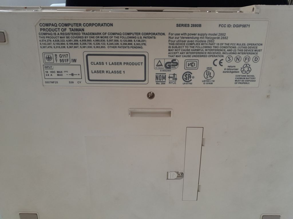
4,928,322, 4,959,860, 4,980,836, 5,097,506, 5,125,088, 5,136,231;
5,142,247, 5,155,004, 5,199,888, 5,208,736, 5,245,328, 5,258,888, 5,303,378;
5,307,476, 5,357,619, 5,367,647, 5,381,530, 5,382,993. OTHER PATENTS PENDING.
SERIES 2880B FCC ID: DGIP5871
For use with power supply model 2882
Nur zur Verwendung
65 to 200 ⋅C January 1989 1/6 BCY58-BCY59 THERMAL DATA R th j-caseThermal Resistance Junction-case Max 150 ⋅C/W R Thermal Resistance Junction-ambient Max 450 ⋅C/W th j-amb ELECTRICAL CHARACTERISTICS (T amb = 25 ⋅C unless otherwise specified) Symbol Parameter Test Conditions Min. Typ. Max. Unit ICES Collector
------- Ich kann das Alter nicht nachvollziehen, schätze die TO-18 / TO-5 mit Gold auf 70er / max. Anfang 80er Jahre.
die Eigenschaften der Transistoren mit der Zeit etwas geändert. Garantiert sind nur die Min- und Max-Werte aus den Tabellen der Kenndaten (Eigenschaften). Und das sind nicht viele. Alle anderen Angaben, auch die Diagramme, sind unverbindlich. Bernhard
· Case Material: Transfer Molded Epoxy. UL Flammability DO-201 Classification Rating 94V-0 Dim Min Max · Moisture Sensitivity: Level 1 per J-STD-020C A 25.40 — · Terminals: Finish - Bright Tin. Leads: Axial, Solderable B 8.50 9.53 per MIL-STD-202 Method 208 0.96 1.06 · Ordering Information: See Last
A I Pulsed Collector Current t limited by T 90 A CM p joax PD Maximum Power Dissipation @ T=17j C 208 W Diode Symbol Description Values Unit V Repetitive Peak Reverse Voltage 650 V RRM IF Diode Continuous Forward Current 30 A IFM Diode Maximum Forward Current t lpmited by T jmax 90 A Discrete Symbol
SUBPART J APPLICABLE AT THE DATE OF MANUFACTURE. COMPLY WITH DHHS RULE 21 CFR CAMBRIDGE, CB5 9PB. MAX WARNING: THIS APPLIANCE MUST BE EARTHED. Amplifier Board L924 Contents Circuit description Component overlay Parts list Circuit diagrams The line ‘NFB’ provides for a portion of the negative feedback
place.The compressors will withstand storage temperatures down to -35°C. Condensing temperatures: Max. 60°C at stable conditions and max. 70°C at peak load. Ambient temperatures: Min. -10°C, max. 55°C The BD compressor concept includes an electronic unit which features overload protection, battery protection
codes Max. 6 per component hand scanner. An audible and opti- Number of filters cal signal acknowledges a suc- cessful reading operation. If the la- to extract relevant data Max. 1 per bar code bel is damaged
AAA Energizer Max (Singapore) AAA Energizer Max aus IR-FB gebr. MHD 12-2030 MHD 12-2030 Kauf 10-2020 Kauf 10-2020 17. Oktober 2021 15. Mai 2024 Entladung mit: 30 mA Entladung mit: 30 mA mAh max: 1197 mAh max: 1100 Time
Voltage Reference with Force and Sense on Output and Ground": https://www.mouser.de/datasheet/2/609/MAX5717_MAX5719-3130212.pdf Nun steht in der Abbildung im Datenblatt ein OpAmp am Ausgang, welcher mit +5V und -5V betrieben wird. -5V habe ich nicht, daher habe ich diesen ersten "Buffer" direkt mit
TL072 danach? Du hast doch keine hochohmige Quelle. Da wäre wohl ein OP37 besser (wenn du schon einen MAX5719 nimmst...)
. There are two cases that give a transition without Compare Match. OCR0A changes its value from MAX, like in Figure 15-7. When the OCR0A value is MAX the OCn pin value is the same as the result of a down-counting Compare Match. To ensure symmetry around BOTTOM the OCn value at MAX must correspond
Figure 20-10. Single-Slope Pulse Width Modulation Period (T) CMPn=BOTTOM CMPn=TOP "update" "match" MAX TOP CNT CMPn BOTTOM Output WOn The TCA.PER register defines the PWM resolution. The minimum resolution is 2 bits (TCA.PER=0x0003), and the maximum resolution is 16 bits (TCA.PER=MAX). The following
generated when the CNT is equal to TOP. If TOP is updated to a value lower than CNT, upon reaching MAX, an OVF interrupt and event is generated, and the counter restarts from BOTTOM. Figure 22-3. Periodic Interrupt Mode CAPT MAX and Event) Request (Interrupt Request and Event) TOP CNT BOTTOM TOP changed
-Treiber-Elektronik die Sende-Stufe mit einer Art Tristate-Modus abschalten können. Beim bekannten MAX232 geht das leider nicht, dafür aber bei den Typen ICL3321 und MAX242. Tx: cmd arg0 arg1 ... argX/n Rx: cmd arg0 arg1 ... argX/n Beide verfügen über Low-Power-Shut- replyline1/n down-Modi, die sogar
lead-frame. • For automotive applications requiring specific change Solderable per MIL-STD-202, Method 208 control (i.e.: parts qualified to AEC-Q100/101/200, PPAP • Weight: 0.0062 grams (approximate) capable, and manufactured in IATF 16949 certifi ed facilities), please refer to the related automotive grade
) * for KP/MKP P=5; 7.5mm and L=10.5mm:Tmax. = 250°C for 3s Pre-heating: it must be made at +110°C max. for 1 min. max. (+100°C max. for KP/ MKP units with leads pitch P≤ 7.5mm or axial units with body length L≤ 10.5mm). Avoid excessive thermal stress which mayresult in the capacitors damage, inparticular
Frequenzschritt. 162 Das wird durch die Simulationszeit im Zeitbereich festgelegt und so erhält man bei max= 10ms 1 / max= 1 / 10ms = 100Hz b) Die höchste im Diagramm darstellbare Frequenz (= Stoppfrequenz beim AC-Sweep….) sowie der Dynamikbereich der FFT-Anzeige werden durch die Samplefrequenz bei der Time-Domain
Recommendations Profile Feature Pb-Free Assembly Tp Preheat / Soak: Tc-5 °C Temperature Min. (T ) 150 °C MAX. RAMP UP RATE = 3 °C/s p smin MAX. RAMP DOWN RATE = 6 °C/s Temperature Max. (T smax) 200 °C TL Time (s ) from (sminto Tsmax) 60~120 seconds Tsmax PREHEAT AREA L ) Ramp Up Rate (T tL T )p 3 °C / second
latched at the trigger to assist in point placement. There are three decimation modes: normal, min/max, and hires: H Normal (sub-sample) mode throws away samples between saved sample points. H Min/max mode saves the maximum and minimum samples over the decimation interval. H Hires mode gives extra resolution
geworden. Nett fand ich übrigens (und finde ich noch immer) diese flachen schwarzen Gehäuse von den BC208 und BC115. Benutzt habe ich solche zwar nie, aber ich erinnere mich noch, dass ich als Kind mal einen Fernseher geschlachtet habe, bei dem die Platine voll mit diesen Dingern war. Ich entdeckte den
sie an einen Scanner adaptiert, wow, geht! > Wie heißt der 'Typ'? Bedrahtet dürfte der Verstärker max. bis 300/450MHz verwendbar sein?

 Bild
 Bild