-
PDF
M220SP01_V.0.pdf
Logic Level “0” Y 0.8 Volts Fall Time Max 80N of minimum pixel clock period Rise Time Max O0% of minimum pixel clock period Monotonic Rise/Fall Voltage range 0.5-2.4 Volts S E Overshoot/Undershoot L0% of high level signal voltage range No signal
in „[S] TFT Steuerplatinen“ · Markt ·
-
PDF
ETM12E_03_R8564LC.pdf
* Unless otherwise specified, GND = 0 V , Ta = +25 °C , DD = 3.0 V Item Symbol Comments Min. Typ. Max. Unit ( Typ. ) Output frequency fo 32.768 kHz Frequency precision ∆ f / f Ta = +25 °C 5 ± 23 (1)∗2) × 106 VDD = 3.0 V Frequency Ta = +25 °C ( Max. ) −6 voltage f / V V DD = 1.8 V to 5.5 V ± 2 × 10 /
in „Kompatible zu RX8564LC“ · Mikrocontroller und Digitale Elektronik ·
-
PDF
ETM12E_03_R8564LC.pdf
* Unless otherwise specified, GND = 0 V , Ta = +25 °C , DD = 3.0 V Item Symbol Comments Min. Typ. Max. Unit ( Typ. ) Output frequency fo 32.768 kHz Frequency precision ∆ f / f Ta = +25 °C 5 ± 23 (1)∗2) × 106 VDD = 3.0 V Frequency Ta = +25 °C ( Max. ) −6 voltage f / V V DD = 1.8 V to 5.5 V ± 2 × 10 /
-
Datei
W1394_trace.txt
-11:37:25:767 IOCTL_ISOCH_ALLOCATE_BANDWIDTH 00000046 k1394upfi 1004 3132 3 46 10\02\2018-11:37:25:768 CompletionParams Type=255 00000047 k1394upfi 1004 3132 3 47 10\02\2018-11:37:25:768 Completion status= SUCCESS Type=255 00000048 k1394upfi 1004 3132 3 48 10\02\2018-11:37:25:768 Bufferlength=0 flags=0x1074135088 Mdlused=0 00000049 k1394upfi 1004 3132 3 49 10\02\2018-11:37:25:768 WdfRequestRetrieveOutputBuffer failed 0xc0000023(STATUS_BUFFER_TOO_SMALL) 00000050 k1394upfi 1004 3132 3 50 10\02\2018-11:37:25:768 Contents of systemBuffer <NULL> 00000051 k1394upfi 1004 3132 3 51
in „R&S TSMU Radio Network Analyzer“ · HF, Funk und Felder ·
-
PDF
Platinendaten.pdf
50A 10 85,10 33,00 28,083 0,281 0,003 71 710 G Dig.-Ausgänge 12 89,00 69,00 61,410 0,614 0,006 314 3.768 H Relais kurz 12 68,20 108,70 74,133 0,741 0,007 194 2.328 I Relais lang 20 68,20 129,70 88,455 0,885 0,009 202 4.040 J Netzteil 12 100,00 84,90 84,900 0,849 0,008 330 3.960 K Hauptnetzteil 1 160,00
in „Suche jemand, der mir 194 Platinen herstellt“ · Platinen ·
-
PDF
RDA5807SP.pdf
Profile Profile Feature Sn-Pb Eutectic Assembly Pb-Free Assembly o o Average Ramp-Up Rate 3 C/second max. 3 C/second max. (TSmax to Tp) Preheat o o -Temperature Min (T smin 100 C 150 C o o -Temperature Max (T smax 100 C 200 C -Time (tsmino tsmax 60-120 seconds 60-180 seconds Time maintained above: o o
in „Hilfe benötigt bei RDA5807SP Ansteuerung“ · Mikrocontroller und Digitale Elektronik ·
-
PDF
B400_RV-3049-C2.pdf
reel with 1'000 parts Option C: not compensated 13” (330 mm) reel with 5'000 parts BLOCKDIAGRAM: 32.768 kHz Xtal On / Off Ctrl 00 IRQ Ctrl OSC DIVIDER Control 3 and Control 4 TEMPERATURE Seconds CLKOUT COMPENSATION Minutes LOGIC Hours CLKOE OUTPUT Date CONTROL Weekday INT Month Year Seconds Alarm VDD
in „Uhrbaustein gesucht“ · Mikrocontroller und Digitale Elektronik ·
-
PDF
Datenblatt__M8716B_.pdf
extendedperiods may affect devicereliability. ELECTRICAL CHARACTERISTICS (TA = 25°C : VDD =5V ; F OSC = 32.768kHzif not otherwise specified) Symbol Parameter Test Conditions Min. Typ. Max. Unit VDD Supply Voltage 4.5 5.0 5.5 V IDD Supply Current 1 mA V BAT Supply Voltage (standby operation) No Data Transfer
in „RTC Chip von ST, kein Datenblatt zu finden! HELP PLZ!“ · Mikrocontroller und Digitale Elektronik ·
-
Datei
main.c
Timer #ifdef direkt #define PWM_STEPS 256 // PWM-Schritte pro Zyklus(1..256) #else #define PWM_STEPS 768 // PWM-Schritte pro Zyklus(1..768) #endif #define PWM_PORT PORTB // Port für PWM #define PWM_PORT2 PORTC // Port für PWM #define PWM_PORT3 PORTD // Port für PWM #define PWM_DDR DDRB // Datenrichtungsregister
in „AVR/GCC: pgm_read_byte funktioniert, pgm_read_word nicht?“ · Mikrocontroller und Digitale Elektronik ·
-
PDF
ATMLH412-ATMEL.pdf
Serial EEPROM • 64-byte Page Write Mode (Partial Page Writes Allowed) • Self-timed Write Cycle (5 ms Max) 256K (32,768 x 8) • High Reliability ⎯ Endurance: One Million Write Cycles ATMLH412 ⎯ Data Retention: 40 Years • Lead-free/Halogen-free Devices Available • 8-lead JEDEC PDIP, 8-lead JEDEC SOIC, EIAJ
-
PDF
rv-3029-c2.pdf
5'000 parts -40°C to +85°C ± 2.17 s/day ±25ppm -40°C to +125°C ± 2.60 s/day ±30ppm BLOCKDIAGRAM: 32.768 kHz On / OFF Ctrl00 Xtal IRQ Ctrl IRQ Flags OSC DIVIDER Status and Rst Ctrl TEMPERATURE Seconds 08 CLKOUT COMPENSATION Minutes LOGIC Hours CLKOE OUTPUT Date CONTROL Weekday INT Month Year Seconds Alarm
in „18650 Zelle zu 5V“ · Analoge Elektronik und Schaltungstechnik ·
-
PDF
Si473x-B20.pdf
V = 2.7 to 5.5 V,= 1.5 to 3.6 V, T = –20 to 85 °C) DD IO A Parameter Symbol Test Condition Min Typ Max Unit Reference Clock RCLK Supported Frequencies 1 31.130 32.768 40,000 kHz RCLK Frequency Tolerance 2 –100 — 100 ppm REFCLK_PRESCALE 1 — 4095 REFCLK 31.130 32.768 34.406 kHz Crystal Oscillator Crystal
in „Si47xx Programming Guide“ · Mikrocontroller und Digitale Elektronik ·
-
PDF
TBU-CA.pdf
CAVITY G (MEASURED AT HUB) USER DIRECTION OF FEED QUANTITY: 3000 PIECES PER REEL A B C D G N Min. Max. Min. Max. Min. Max. Min. Max. Ref. Ref. 326 330 1.5 2.5 12.8 13.5 20.2 16.5 102 - (12.835) (13.002) (.059) (.098) (.504) (.531) (.795) (.650) (4.016) A 0 B 0 D D1 E F Min. Max. Min. Max. Min. Max. Min. Max. Min. Max. Min. max. 4.3 4.5 6.7 6.9 1.5 1.6 1.5 - 1.65 1.85 7.4 7.6 (.169) (.177) (.264) (.272) (.059) (.063) (.059) (.065) (.073) (.291) (.299) K 0 P P0 P2 t W Min. Max. Min. Max. Min. Max. Min. Max
in „USB selbstrückstellende Schutzschaltung bis 24V“ · Mikrocontroller und Digitale Elektronik ·
-
PDF
DS1337.pdf
ELECTRICAL CHARACTERISTICS (V = 1.3V to 1.8V, T = -40°C to +85°C.) CC A PARAMETER SYMBOL CONDITIONS MIN TYP MAX UNITS Timekeeping Current OSC (Notes 4, 6, 7) 600 nA (Oscillator Enabled) Data Retention Current (Oscillator Disabled) DDR (Note 4) 50 nA CRYSTAL SPECIFICATIONS* PARAMETER SYMBOL MIN TYP MAX UNITS Nominal Frequency fO 32.768 KHz Series Resistance ESR 45 kW Load Capacitance CL 6 pF *The crystal, traces, and crystal input pins should be isolated from RF generating signals. Refer to Application Note 58: Crystal Considerations
in „Atmega8 hängt in TWI Kommunikation fest (START schlägt fehl)“ · Mikrocontroller und Digitale Elektronik ·
-
PDF
doc8002.pdf
note describes a fast and accurate way to calibrate the internal RC oscillator using an external 32.768 kHz crystal as input to an asynchronous Timer/Counter. Rev. 8002C-AVR-02/06 2 Theory of operation – the internal RC oscillator In production the internal RC is calibrated at either 5V or 3.3V. Refer
in „Genauigkeit interner Oszillator Mega8 ...“ · Mikrocontroller und Digitale Elektronik ·
-
PDF
DS1302_DAL.pdf
DroV 0.7 V TD *Unless otherwise noted. CAPACITANCE (A = 25⋅C) PARAMETER SYMBOL CONDITION TYP MAX UNITS NOTES Input Capacitance CI 10 pF I/O Capacitance CI/O 15 pF Crystal Capacitance C X 6 pF AC ELECTRICAL CHARACTERISTICS (0⋅C to 70⋅C; V = +5V 〉 10%*) CC PARAMETER SYMBOL MIN TYP MAX UNITS NOTES
-
PDF
DS1302.pdf
DroV 0.7 V TD *Unless otherwise noted. CAPACITANCE (A = 25⋅C) PARAMETER SYMBOL CONDITION TYP MAX UNITS NOTES Input Capacitance CI 10 pF I/O Capacitance CI/O 15 pF Crystal Capacitance C X 6 pF AC ELECTRICAL CHARACTERISTICS (0⋅C to 70⋅C; V = +5V 〉 10%*) CC PARAMETER SYMBOL MIN TYP MAX UNITS NOTES
in „DS1302 zu langsam“ · Mikrocontroller und Digitale Elektronik ·
-
PDF
esp_wroom_32_datasheet_en.pdf
second max Preheat Temperature Min. (T sin.) 150°C Temperature Typ. (T Typ.) 175°C s Temperature Min. (T sax.) 200°C Time (Ts) 60 ~ 180 seconds Ramp-up rate (T L to TP) 3°C/second max Time maintained above: –Temperature (T )LTime (T )L 217°C/60 ~ 150 seconds Peak temperature (T P 260°C max, for 10 seconds Target peak temperature (TPTarget) 260°C +0/-5°C Time within 5°C of actual peak (P ) 20 ~ 40 seconds TSmax to T (Lamp-down Rate) 6°C/second max Tune 25°C to Peak Temperature (t) 8 minutes
-
PDF
RDA5807SP_ProgManual_2.5.pdf
结束整个操作。 (3)、连续读写方式时续图: 图 1 写数据时序 图 2 读数据时序 I2C Timing Characteristics Parameter Symbol Test Min Typ Max Unit Condition SCLK Frequency fscl 0 - 400 KHz SCLK High Time thigh 0.6 - - us SCLK Low Time tlow 1.3 - - us Setup Time for START tsu:sta 0.6 - - us Condition The information contained herein is the
-
PDF
62256-80.pdf
I Output Leakage Current -1 1 uA OL /OE=V INV IOV to V CC Output Low Voltage V =MAX, I = 1mA 0.4 V OL CC OL V V OH Output High Voltage VCCMIN, I OH= -1mA 2.2 V Operating Power Supply /CE=V ILIDQ=0mA, ICC 20 mA Current F=F MAX=1/ RC ICCSB TTL Standby Supply /CE=V IHIDQ=0mA, 1 mA /CE
in „Retro SRAM alternative NEC C43256-12L“ · Mikrocontroller und Digitale Elektronik ·
-
PDF
FM24C256_20data_20sheet.pdf
accessing the FM24C256, the user addresses the bus is the master. The master is responsible for 32,768 locations each with 8 data bits. These data bits are shifted serially. The 32,768 addresses are generating the clock signal for all operations. Any device on the bus that is being controlled is a slave
in „FRAM von RAMTRON“ · Mikrocontroller und Digitale Elektronik ·
-
Datei
DS10-g0133-PID.c
Ki 0,003 sollwertsprung abhängig vom Sektor: if ((temp16 > 400)&&(sector<545))sollwert=408; // esum max 18400-->18000; esum min 10 000 ->7 000; // DS10_0113 190219 Kp 0.07->0.08, Ki 0,003 --> 0,004 // esum max 1800-->13500; esum min 5 000; // DS10_0114 190220 Kp 0.08 -> 0,1, Ki 0,004 // esum max 13500
in „while-Schleife wird "unerlaubt verlassen"“ · Mikrocontroller und Digitale Elektronik ·
-
PDF
AK5388AEQ.pdf
pin should be connected to VSS1-6 ABSOLUTE MAXIMUM RATINGS (VSS1-6=0V; Note 1) Parameter Symbol min max Unit Power Supplies: Analog AVDD1 0.3 6.0 V Analog AVDD2 0.3 6.0 V Digital DVDD1 0.3 6.0 V Digital Output Buffer DVDD2 0.3 6.0 V Input Current, Any Pin Except Supplies IIN 10 mA Analog Input
in „Audio-ADC - Taktfrequenzen I2S“ · Mikrocontroller und Digitale Elektronik ·
-
Datei
DS10-g0134-PID.c
Ki 0,003 sollwertsprung abhängig vom Sektor: if ((temp16 > 400)&&(sector<545))sollwert=408; // esum max 18400-->18000; esum min 10 000 ->7 000; // DS10_0113 190219 Kp 0.07->0.08, Ki 0,003 --> 0,004 // esum max 1800-->13500; esum min 5 000; // DS10_0114 190220 Kp 0.08 -> 0,1, Ki 0,004 // esum max 13500
in „while-Schleife wird "unerlaubt verlassen"“ · Mikrocontroller und Digitale Elektronik ·
-
PDF
DS1302.pdf
Voltage Drop VTD 0.7 V *Unless otherwise specified. CAPACITANCE (TA= 25ºC) PARAMETER SYMBOL MIN TYP MAX UNITS NOTES Input Capacitance C 10 pF I I/O Capacitance C I/O 15 pF Crystal Capacitance CX 6 pF AC ELECTRICAL CHARACTERISTICS (Over the operating range*) PARAMETER SYMBOL MIN TYP MAX UNITS NOTES Data
in „genauer TIMER“ · Mikrocontroller und Digitale Elektronik ·
-
PDF
DS1302.pdf
Voltage Drop VTD 0.7 V *Unless otherwise specified. CAPACITANCE (TA= 25ºC) PARAMETER SYMBOL MIN TYP MAX UNITS NOTES Input Capacitance C 10 pF I I/O Capacitance C I/O 15 pF Crystal Capacitance CX 6 pF AC ELECTRICAL CHARACTERISTICS (Over the operating range*) PARAMETER SYMBOL MIN TYP MAX UNITS NOTES Data
in „RTC DS 1302“ · Mikrocontroller und Digitale Elektronik ·
-
PDF
stm32g030c6.pdf
Tabelle 35. Merkmale des langsamen externen Benutzertakts(1) Symbol Parameter Bedingungen Mindest Typ Max Einheit fLSE_ext Frequenz der externen Taktquelle des Benutzers - - 32.768 1000 kHz VLSEH OSC32_IN Eingangspin Hochpegelspannung - 0,7 VDDIO1 - VDDIO1 V - - VLSEL OSC32_IN Eingangspin niedrige Spannung
in „Muß der STM32G programmiert werden?“ · Mikrocontroller und Digitale Elektronik ·
-
Datei
DS10-g0120-PID.c
Ki 0,003 sollwertsprung abhängig vom Sektor: if ((temp16 > 400)&&(sector<545))sollwert=408; // esum max 18400-->18000; esum min 10 000 ->7 000; // DS10_0113 190219 Kp 0.07->0.08, Ki 0,003 --> 0,004 // esum max 1800-->13500; esum min 5 000; // DS10_0114 190220 Kp 0.08 -> 0,1, Ki 0,004 // esum max 13500
in „while-Schleife vorzeitig verlassen“ · Mikrocontroller und Digitale Elektronik ·
-
PDF
62256.pdf
Features Packages High-speed: 35, 70 ns – 28-pin TSOP (Standard) Ultra low DC operating current of 5mA (max.) – 28-pin 600 mil PDIP – 28-pin 330 mil SOP (450 mil pin-to-pin) Low Power Dissipation: – TTL Standby: 3 mA (Max.) – CMOS Standby: 20 A (Max.) Description Fully static operation The V62C518256 is a
in „Erfahrungen mit Pufferakku fuer RAM“ · Mikrocontroller und Digitale Elektronik ·
-
PDF
CSR1010_Data_Sheet_CS-231985-DS.pdf
of 48 © Cambridge Silicon Radio Limited 2012 - 2015 CS-231985-DSP6 www.csr.com Sleep Clock Min Typ Max Units Frequency 30 32.768 35 kHz (a) (b) Frequency tolerance - - 250 ±ppm Frequency trim range - 50 - ±ppm Drive level - 0.4 - V Load capacitance - - 10 pF Equivalent series resistance 40 - 65 kΩ Duty
in „I²C Daten über Bluetooth übertragen?“ · Mikrocontroller und Digitale Elektronik ·
-
PDF
datasheet.pdf
white mode. This TFT-LCD has a 13.3 inch diagonally measured active display area with XGA resolution(768 vertical by 1024 horizontal pixel array). Each pixel is divided into Red, Green and Blue sub-pixels or dots which are arranged in vertical stripes. Gray scale or the brightness of the sub-pixel color
in „HDMI/CV zu LVDS“ · Mikrocontroller und Digitale Elektronik ·
-
 Bild
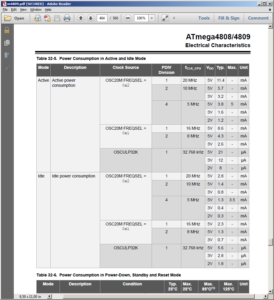
Tabelle zum Stromverbrauch eines ATmega4808/4809 Mikrocontrollers
mA OSCULP32K 1 32.768 kHz 5V 21 µA 3V 12 µA 2V 8 µA Idle Idle power consumption OSC20M FREQSAL = 0x2 1 20 MHz 5V 2.8 mA 2 10 MHz 5V 1.4 mA 4 5 MHz 3V 0.8 mA 5V 1.3 3.5 mA 3V 0.4 2V 0.3 mA OSC20M FREQSAL = 0x1 1 16 MHz 5V 2.3 mA 2 8 MHz 5V 1.3 mA 3V 0.7 mA OSCULP32K 1 32.768 kHz 5V 5.6 µA 3V 2.8 µA 2V 1.8 µA Table 32-6. Power Consumption in
in „AVR ATtiny Stromaufnahme“ · Mikrocontroller und Digitale Elektronik · · Screenshots
-
PDF
STM32_DS1307.pdf
= DECtoBCD(19); //Begin: Exercise 2 uint8_t x = 0x93;//Set register 0x07 to 0x93 = 10010011 for 32.768kHz sq-wave; HAL_I2C_Mem_Write(&hi2c1, 0x68 << 1, 0x07, 1, &x, 1, HAL_MAX_DELAY); //End: Exercise 2 RTC_Set_Time_Date(&rtc); while (1){ RTC_Get_Time_Date(&rtc); USB_Info_RTC(&rtc); HAL_Delay(1000); }
in „I2C STM32F103“ · Mikrocontroller und Digitale Elektronik ·
-
PDF
X1226.pdf
year correction, automatic adjustment up to the year 2096. —32.768kHz, 4096Hz, 1Hz • 512 x 8 bits of EEPROM Two nonvolatile bits select one of three divisions of the —64-byte page write mode oscillator to be placed on the PHZ pin.A fourth selection —3-bit Block Lock
in „kann RTC X1226 nicht beschreiben“ · Mikrocontroller und Digitale Elektronik ·
-
PDF
nRF24LE1_Product_Specification_rev1_6-6439.pdf
the 16 MHz on-chip oscillators) X One 16-bit timer/counter operating at the low frequency clock (32.768 kHz) • On-chip oscillators: X 16 MHz crystal oscillator XOSC16M X 16 MHz RC-oscillator RCOSC16M X 32.768 kHz crystal oscillator XOSC32K X 32.768 kHz RC-oscillator RCOSC32K • Power management function
in „Projekt: Kugelschreiber-Morse“ · Mikrocontroller und Digitale Elektronik ·
-
PDF
RV-3032-C7_App-Manual-rev1.3.pdf
to 5.5 V, TYP values at 25°C and 3.0 V. Oscillator Parameters: SYMBOL PARAMETER CONDITIONS MIN TYP MAX UNIT Xtal General F Crystal Frequency 32.768 kHz Oscillator start-up time at TA= 25°C 0.1 0.5 START VDD = 3.0 V T = -40 to +105°C 3 s A VSTART Oscillator start-up voltage TA= -40 to +105°C 1.3 V Frequency
in „ATtiny85 + Uhrenquarz mit 10 pF CL: Kondensatoren“ · Analoge Elektronik und Schaltungstechnik ·
-
PDF
LM151X3-A2.pdf
RH Max. Ta 40º : Absolute Humidity shall be less than Ta = 40 º 90%RH . These shall be no dew condensation. 2. Humidity Min. 5%RH, Max. 90%RH Alpha Point Ltd. P.O. Box 41 Tel.: +358-9-34 64 34 1 http://www.alpha.fi
in „Mikrocontroller und 15'' TFT LCD“ · Mikrocontroller und Digitale Elektronik ·
-
PDF
NSL_32SR3S.pdf
Circuit Schematic Electrical Characteristics (TA=25°C unless otherwise noted) Symbol Parameter Min. Typ. Max. Units Test Conditions LED IF Forward Current 40 mA (2) V Forward Voltage 2.0 V I = 16 mA F F IR Reverse Current 100 μA VR= 4V Cell VC Maximum Cell Voltage 60 V (Peak AC or DC) PD Power Dissipation
in „Spannungsgeregelter Widerstand“ · Analoge Elektronik und Schaltungstechnik ·
-
PDF
MC-206.pdf
. 1.5 pF Max. Insulation resistance IR 500 MΩ Min. Aging fa ±3 x 10 -/ year Max. ±5 x 10 / year Max. Ta= +25 °C ±3 °C, first year Three drops on a hard board from 750 mm or excitation test Shock resistance S.R. ±5 x10 Max. 2 with 29400m/s x0.3msx1/2sinewavex3directions 5AHEA HA E J= ?A Frequency (kHz) 32 ≤ f < 38 38 ≤ f < 65.536 65.536 ≤ f < 75 75 ≤ f ≤100 Series resistance (Ω ) 50 kΩ Max. 40 kΩ Max. 25 kΩ Max. 20 kΩ
in „Ist das ein Quartz?“ · Mikrocontroller und Digitale Elektronik ·
-
PDF
ATxmega_schematic.pdf
Battery Backup Module supply VBAT 1.8 V to 3.6 V voltage GND Ground To run the Real Time Counter a 32.768 kHz crystal oscillator must be connected between the Notes TOSC1 and TOSC2 pins when running from VBAT. 3 8278B-AVR-03/10 2.3 External Analog Reference Connections The following schematic checklist
in „Stromversorgung XMega“ · Mikrocontroller und Digitale Elektronik ·
-
PDF
pcf8573.pdf
interruptions is provided by a 1.2 V nickel cadmium interruption battery. The time base is generated from a 32.768 kHz • Crystal oscillator control (32.768 kHz) crystal-controlled oscillator. • Low power consumption. 3 QUICK REFERENCE DATA SYMBOL PARAMETER MIN. TYP. MAX. UNIT VDD − VSS1 supply voltage, clock (pin
in „DS3231 vs PCF8573, hilfe gesucht !“ · Mikrocontroller und Digitale Elektronik ·
-
PDF
C9612.pdf
完全集成的片上RF VCO FM模式的耗电电流小于25mA , 完全集成的片上环路滤波器 AM模式的耗电电流小于20mA 支持手动搜台 支持全球FM/AM波段 支持32.768KHz 晶体振荡器 AM波段520-1710 KHz 自动的频率控制(AFC) FM波段87-108MHz 支持数字自动增益控制 (AGC) 支持FM单波段64-108 MHz 数字自适应噪声对消 集成数字低中频调谐器 单声道/立体声自动切换 镜像抑制下变频器 FM/AM各个地区频率波段选择 高性能A/D转换器 封装类型: SOP16 (符合RoHS
in „Radio Chip Datenblatt“ · Analoge Elektronik und Schaltungstechnik ·
-
PDF
xmega_a1.pdf
Counter (RTC). The RTC can be clocked from an accurate 32.768 kHz Crystal Oscillator, the 32.768 kHz Calibrated Internal Oscillator, or from the 32 kHz Ultra Low Power Internal Oscillator. The RTC includes both a Period and a Compare register. For details, see
in „Welchen Wert hat der Pull-up-Widerstand dieses XMega?“ · Mikrocontroller und Digitale Elektronik ·
-
PDF
PCF8593.pdf
- - 1 MHz Quartz crystal parameters (f = 32.768 kHz) RS series resistance - - 40 kΩ CL parallel load capacitance - 10 - pF Ctrim trimmer capacitance 5 - 25 pF IC-bus timing (see Figure 21) [2] SCL SCL clock frequency - - 100 kHz SP pulse width of
in „PCF8593 über I2C Bus steuern“ · Mikrocontroller und Digitale Elektronik ·
-
Datei
report.txt
20 20 20 00 00 00 FF 70 | 00 31 30 36 41 4C 31 34 36 30 30 37 31 30 01 8B Product ID Manufacuter :MAX Model ID : 6035 Serial Number : 710 Week Made : 6 Year Made : 2005 EDID Version : 1.3 Extensions : 1 Checksum : 0x8B Video Input Definitions Digital: Gamma: 2,50 Screen Size: Horz:128cm...Vert:90cm
in „DVI-EDID Problem, Monitor wird nicht erkannt“ · Mikrocontroller und Digitale Elektronik ·
-
PDF
RESR_angular_encoder_system_data_sheet.pdf
Nominal external 115 150 200 206 209 229 diameter (mm) 20 µm pitch 18,000 23,600 31,488 32,400 32,768 36,000 Line count 40 µm pitch 9,000 11,800 15,744 16,200 16,384 18,000 114.70 150.40 200.40 206.50 208.80 229.40 DO (mm) 114.50 150.20 200.20 206.10 208.40 229.00 ØDI 95.04 130.04 180.04 186.05 186.05
in „Schrittmotor mit Motortreiber und Encoder in Betrieb nehmen“ · Mikrocontroller und Digitale Elektronik ·
-
PDF
adxl380.pdf
7:4])to0’b0011,whichdividesthe3.072MHzclockby4 togettothe768kHzsystemclockthattheADXL380canoperate atwithlowlatency.Notethatitisimportanttoconfigurethedevice inlowlatencymodeifusinga768kHzsystemclock.SeetheLow LatencyModesectionformoredetails. analog.com Rev.
in „ADXL380 mit SPI auslesen“ · Mikrocontroller und Digitale Elektronik ·
-
PDF
DS_AT32F421_V2.01_EN.pdf
for more details on the resonator characteristics (frequency, package, accuracy). Table 25. LEXT 32.768 kHz crystal characteristics (1)(2) Symbol Parameter Conditions Min Typ Max Unit SU(LEXT) Startup time VDD is stabilized - 180 - ms (1) Oscillator characteristics are given by the crystal/ceramic resonator
in „Firmware entschlüsseln, Updateprogramm als Hilfe?“ · Softwareentwicklung ·
-
PDF
tempf_lm335.pdf
, R = 1 mA 0.3 1 0.5 1.5 ˚C Calibration Calibrated Error at Extended T = T (Intermittent) 2 2 ˚C C MAX Temperatures Non-Linearity IR= 1 mA 0.3 0.5 0.3 1 ˚C Temperature Accuracy (Note 1) LM335, LM335A Parameter Conditions LM335A LM335 Units Min Typ Max Min Typ Max Operating Output Voltage TC = 25˚C, R
in „Temperaturmessung mit μC und LM 335“ · Mikrocontroller und Digitale Elektronik ·