Suchergebnisse für "WS2812B"
HAS ONLY GOT THE ADUIO VISUALIZER MODE USING THE MSGEQ7 FOR OTHER MODES SEE THE "RGBStripe_Control_WS 2812 .ino SKETCH **/ #define USES_POTENTIOMETER 0 // SET THIS TO "1" IF YOU ARE USING POTENTIOMETER FOR BRIGHTNESS CONTROL! #define POT_BRIGHTNESS A2 #define LED_DATA 6 #define NUM_LEDS 300 #define BRIGHTNESS
in
„MSGEQ7 zeigt durchgängig einen Wert unabhängig vom Audiosignal an“
·
Mikrocontroller und Digitale Elektronik
·
20.03.2020 13:37
gives a pulse width of 444nS which is well within spec for the SK6812 but is probably too long for the WS 2812 which needs a 350ns pulse for T0H This WS 2811B library is free software: you can redistribute it and/or modify it under the terms of the GNU Lesser General Public License as published by the Free
in
„STM32 Bluepill -> SK6812 (auf Basis von WS2812B Lib)“
·
Projekte & Code
·
29.10.2023 08:18
3 4 GND L298_OUT1 5 6 L298_OUT2 7 8 L298_OUT4 L298_OUT3 9 10 ATMEGA328 ATMEGA328 5V ATMEGA328P-AU B 1 32 L298_IN4 R4 B L298_ENB 2(PCINT19/OC2B /INT1)PD3 PD2(INT0/PCINT18)31 TX 10K ABSTANDSENSOR C2 WS 2812 _LED 3(PCINT20/XCK/T0)PD4 PD1(TXD/PCINT17) 30 RESET Header-Male-2.54_2x5 22pF GND 4GND PD0(RXD/PCINT16
in
„atmega328 - arduino bootloader flashen - doppelt belegte Pins“
·
Platinen
·
23.04.2020 23:44
OCR0B , r18 // set OCR0B to low val sbrc r0, \bitnum // skip if bit is cleared STORE OCR0B , r19 // set OCR0B to high val WS _put_bit_\bitnum: LOAD r20, TIFR sbrs r20, OCF0A rjmp WS _put_bit_\bitnum .endm BITOUT 7 BITOUT 6 BITOUT 5 BITOUT 4 BITOUT 3 BITOUT 2 BITOUT 1 BITOUT 0 rjmp WS _put1 WS _put_end: STORE TIFR, r22 // clear OCF0A flag STORE OCR0B , r1 // last OCR0B = 0 WS _put_waitfinal: LOAD r20, TIFR sbrs r20, OCF0A rjmp WS _put_waitfinal STORE TCCR0B , r1 // stop timer ret
in
„Serielle Ansteuerung / Protokoll WS2812 RGB LED“
·
Mikrocontroller und Digitale Elektronik
·
16.12.2012 03:27
#include <util/delay.h> #include <avr/io.h> #include <avr/interrupt.h> #include "light_ws 2812 .h" #define F_CPU 8000000UL #define ANZAHL_SPALTEN 24 #define ANZAHL_ZEILEN 24 #define ANZAHL_LEDS (ANZAHL_SPALTEN * ANZAHL_ZEILEN) #define UP 1 #define DOWN 0 struct cRGBW led[ANZAHL_LEDS]; uint16
in
„LED-Matrix mit light_ws2812-library; Ansteuerungsgeschwindigkeit“
·
Mikrocontroller und Digitale Elektronik
·
15.12.2018 12:31
Bild
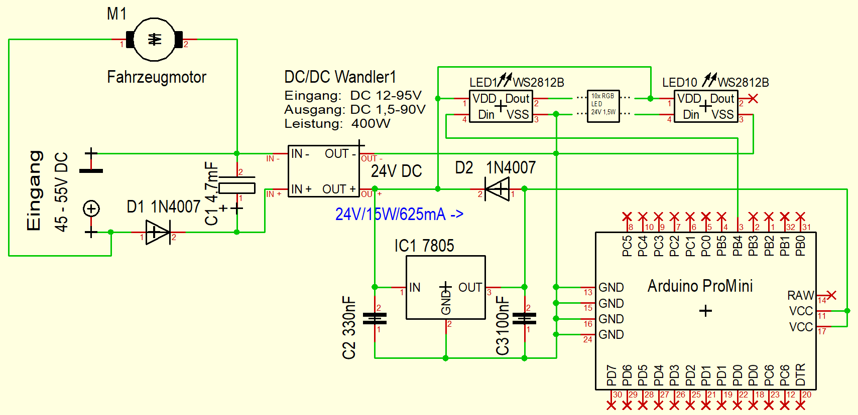
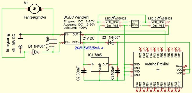
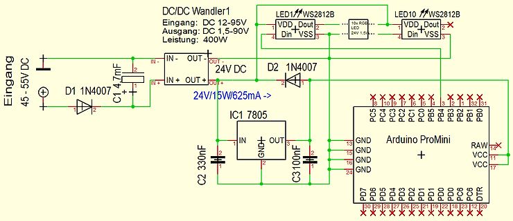
M1 Fahrzeugmotor, DC/DC Wandler1, Eingang: DC 12-95V, Ausgang: DC 1,5-90V, Leistung: 400W, LED1 WS 2812 B , LED10 WS 2812 B , 24V 1,5W, Eingang 45-55V DC, D1 1N407, C1 4,7mF, 24V/15W/625mA, D2 1N407, IC1 7805, C2 330nF, C3 100nF, Arduino ProMini, PC5 bis PC0, PB5 bis PB1, PB0, RAW, VCC, DDR, DT, PD0 bis
in
„DCDC Wandler sterben - Schutzmaßnahmen?“
·
Analoge Elektronik und Schaltungstechnik
·
22.11.2025 12:26
·
Schaltpläne
Bild
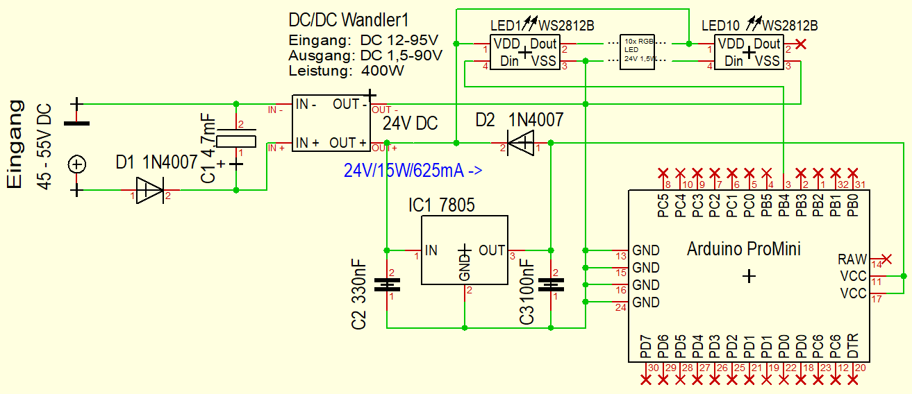
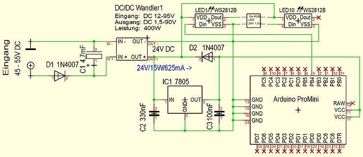
DC/DC Wandler1 Eingang: DC 12-95V Ausgang: DC 1,5-90V Leistung: 400W LED1 WS 2812 B LED10 WS 2812 B VDD Dout VSS Din 24V 1,5V Eingang 45-55V DC D1 1N4007 C1 4,7mF IN- OUT- OUT+ IN+ OUT+ 24V DC D2 1N4007 IC1 7805 24V/15W/625mA -> C2 330nF C3 100nF IN GND OUT GND GND GND Arduino ProMini
in
„DCDC Wandler sterben - Schutzmaßnahmen?“
·
Analoge Elektronik und Schaltungstechnik
·
22.11.2025 11:05
·
Schaltpläne
Bild
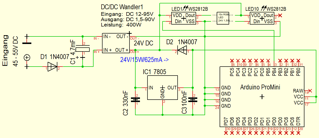
DC/DC Wandler1 Eingang: DC 12-95V Ausgang: DC 1,5-90V Leistung: 400W LED1 WS 2812 B LED10 WS 2812 B 24V 1,5W VDD Dout Din VSS Eingang 45-55V DC D1 1N4007 C1 4,7mF IN- OUT- 24V DC IN+ OUT+ D2 1N4007 24V/15W/625mA -> IC1 7805 IN GND OUT C2 330nF C3 100nF Arduino ProMini GND GND GND
in
„DCDC Wandler sterben - Schutzmaßnahmen?“
·
Analoge Elektronik und Schaltungstechnik
·
22.11.2025 11:19
·
Schaltpläne
voneinander abhängiges Bewegungsschema vorwärts-rückwärts-Drehung rechts-Drehung links - Steuern von einem WS 2812 B RGB LED Ring mit 24-32 LEDs - Bedienung über Balkenmenu auf SH1106-OLED-Display 128 x 64 Pixel - Menu-Steuerung über Drehgeber - Menu viersprachig (DE, EN, FR, ES) Alle Einstellungen bei Veränderung
in
„Unterstützung gesucht, Micropython & Platinenlayout“
·
Markt
·
02.02.2023 13:20
PitschuLight-Controller die Aufgabe, Videodaten zu analysieren und in einen Datenstrom umzuwandeln, der für einen WS 2812 LED-Streifen geeignet ist. Der LED-Streifen wird dabei ringförmig auf die Rückseite des TV geklebt oder z.B . mit entsprechenden ALU-Profilen, die das Licht schön verteilen, montiert. Der Anfang des
in
„Ambilight mit STM32F4discovery und TVP5150AM1“
·
Mikrocontroller und Digitale Elektronik
·
23.11.2014 18:52
LED3 Magenta movwf rgb_byte+6 movlw 0xFF movwf rgb_byte+7 movlw 0xFF movwf rgb_byte+8 call transmit_WS 2812 goto $ ;*******************************************************************************; transmit_WS 2812 movlw high(rgb_byte) movwf FSR0H movlw low(rgb_byte) movwf FSR0L BANKSEL SSP1BUF movf INDF0
in
„[ASM & C] PIC12/PIC18/PIC24 WS2812 SPI Library“
·
Projekte & Code
·
27.01.2014 06:42
rgb_byte+6,ACCESS movlw 0xFF movwf rgb_byte+7,ACCESS movlw 0xFF movwf rgb_byte+8,ACCESS call transmit_WS 2812 goto $ transmit_WS 2812 movlw high(rgb_byte) movwf FSR0H movlw low(rgb_byte) movwf FSR0L movf INDF0,w movwf tx_buf,ACCESS txloop_1 movlw .7 ; Transmit 7 bits movwf tx_cnt,ACCESS txloop_0 movlw b '11111100
in
„[ASM & C] PIC12/PIC18/PIC24 WS2812 SPI Library“
·
Projekte & Code
·
27.01.2014 06:43
R 1 T1 JP10 A 8 3 1 Data RESET GPIO14 GPIO0 A4 IRF9310 B 1 1 IC2A B 9 2 PON GPIO12 GPIO2 C4 3 A9 GPIO13 GPIO15 GPIO15 WS 2812 4 GDN VCC GND R10 100nF LM358N VCC B 0 Q1 4 6 +3V3 2 k 82 BS170 R8 7 DCF77 1 0 0 a R 1 R 1 4 n LED1 680 5 4 12 T t DCF IC2B T DD B O R8
in
„WordClock mit WS2812“
·
Projekte & Code
·
25.01.2026 10:24
#ifndef WS 2818_H_ #define WS 2818_H_ #include <stdint.h> #include <stdbool.h> #include "ws 2812 _config.h" void WS 2818(volatile uint8_t* ddr, uint8_t ddrNewSate, volatile uint8_t* port, uint8_t portNewState, uint8
in
„WS2812b LED-streifen aktualisiert sich erst nach zweitem aufruf“
·
Mikrocontroller und Digitale Elektronik
·
17.04.2020 09:07
(); strip.show(); } void loop(){ if (digitalRead(2) == HIGH){ loop();{ if (go==1) { cli(); ws 2812 _sendarray(display_buffer, NUMBER_OF_PIXELS * 3); sei(); go=0; } } ISR(USART_RX_vect) { unsigned char b ; b =UDR0; if (b == 1) {pos=0; ptr=display_buffer; return;} if (pos == (NUMBER_OF_PIXELS*3)) {} else {*ptr=b ; ptr++; pos++;} if (pos == ((NUMBER_OF_PIXELS*3)-1)) {go=1;} } void ws 2812 _sendarray(uint8_t *data,uint16_t datlen) { uint8_t curbyte,ctr,masklo; uint8_t maskhi = _BV(DATA_PIN); masklo =~ maskhi & DATA_PORT
in
„Auswahl zweier Arduino Sketches“
·
Mikrocontroller und Digitale Elektronik
·
03.12.2014 09:37
Company: Your Company Sheet: 1/1 Date: 2019-05-15 Drawn By: g3gg0.de 1 2 3 4 5 1 2 3 4 5 T VCC ESP32 _ WS 2812 P 2 1 U4 M L L ESP32-WROOM/WROVER T R R I E O D D R 1 2 A R7 N N N 2 1 A 1k O O O S 2 23 16 L L L W S 24O15 I153 W 25O2 G14 VCC5 IO0 26O0 I132 LED5 WDT_WDI 27O4 I124 STATUS 28C I117 DI GND 29C I106 30O5 I925 WS 2812 VCC5 VCC 31O18 I833 APP+ 32O19 I732 APP- VDD DO 33C I635 34O21 I534 ADC RXD0 35XD0 S4NSOR_VN VN TXD0 36XD0 S3NSOR_VP VP 37O22 E2 RESET 38O23 V1D33 39ND GND GND B GND GND1 VCC B DISPLAY Header 1 2
in
„LON Bus Windhager mitlesen/steuern“
·
Softwareentwicklung
·
31.03.2026 22:01
#include <sainsmartkeypad.h> /* Digital Light Wand + SD + LCD + Arduino MEGA - V MRR-3.0 (WS 2812 RGB LED Light Strip) by Michael Ross 2014 Based on original code by myself in 2010 then enhanced by Is0-Mick in 2012 The Digital Light Wand is for use in specialized Light Painting Photography Applications. This code is totally rewritten using code that IsO-Mick created made to specifically support the WS 2812 RGB LED strips running with an SD Card, an LCD Display, and the Arduino Mega 2560 Microprocessor board. The functionality that is included in this code is as follows: Menu System 1 - File select
in
„arduino display geht aus“
·
Mikrocontroller und Digitale Elektronik
·
06.11.2014 14:07
1 2 3 4 5 6 7 8 9 10 11 12 13 A A checked LED GND LED3 C13 LED7 C14 WS 2812 -SMD2020 100nf WS 2812 -SMD2020 100nf VOUT 4 +5V DOUT 1 4 +5V DOUT 1 3 DIN GND 2 3 DIN GND 2 LED GND GND BATTERY CHARGER checked B B VIN C28 C19 C24 GND 22uf 100nf 100nf GND U11 N 10uf BQ25896RTWT G
in
„Möglicher Fehler mit AO3400 und Bauteilen U4 Bruce github“
·
Mikrocontroller und Digitale Elektronik
·
08.01.2025 19:03
1 2 3 4 5 6 7 8 9 10 11 12 13 A A checked LED GND LED3 C13 LED7 C14 WS 2812 -SMD2020 100nf WS 2812 -SMD2020 100nf VOUT 4 +5V DOUT 1 4 +5V DOUT 1 3 DIN GND 2 3 DIN GND 2 LED GND GND BATTERY CHARGER checked B B VIN C28 C19 C24 GND 22uf 100nf 100nf GND U11 N 10uf BQ25896RTWT G
in
„Möglicher Fehler mit AO3400 und Bauteilen U4 Bruce github“
·
Mikrocontroller und Digitale Elektronik
·
08.01.2025 19:07
/* * Ws IntSpi.c * * Created: 02.11.2018 16:32:20 * Author: Thomas */ #include <stdbool.h> #include "sam.h" #include "clocks.h" #include "IO.h" #include "Ws 2812 Spi.h" #define RAM_FUNC __attribute__ ((long_call
in
„ATSAM WS2812B?“
·
Mikrocontroller und Digitale Elektronik
·
29.03.2019 19:46
Descriptions PIN NO. ‡ § NAME 179-PING 176-PINP 128-PINP I/O/Z PU/PD DESCRIPTION HH GF BK XINTF SIGNALS (2812 ONLY) XA[18] D7 158 − O/Z − XA[17] B 7 156 − O/Z − XA[16] A8 152 − O/Z − XA[15] B 9 148 − O/Z − XA[14] A10 144 − O/Z − XA[13] E10 141 − O/Z − XA[12] C11 138 − O/Z − XA[11] A14 132 − O/Z XA[10] C12 130
in
„Wieder eine Elektronik-Anfängerfrage“
·
Mikrocontroller und Digitale Elektronik
·
23.07.2009 21:32
AMBILIGHTBRIGHTNESS = 75; # define COLOR_ORDER GRB // Colour order of LED strip [GRB] # define LED_TYPE WS 2812 B // LED string type [WS 2812 B ] # define DC_OFFSET 0 // DC offset in aux signal [0] # define NOISE 0 // Noise/hum/interference in aux signal [0] # define SAMPLES 64 // Length of buffer for dynamic
in
„Arduino Sketch mittels Kippschalter anders "loopen" lassen“
·
Projekte & Code
·
03.06.2022 10:35
DCMI D0 -> C6 D1 -> C7 D2 -> C8 D3 -> C9 D4 -> E4 -> C11 D5 -> B 6 D6 -> E5 D7 -> E6 HSYNC -> A4 VSYNC -> B 7 PCLK -> A6 I2C SCL -> B 8 SDA -> B 9 Ausgaenge WS 2812 -> B 0 IR -> E9 Beliebige Connections: FID -> E15 -> A2 RESETB -> E14 -> D1 VBLK -> E13 -> E12 AVID -> E12
in
„Ambilight mit STM32F4discovery und TVP5150AM1“
·
Mikrocontroller und Digitale Elektronik
·
21.07.2014 13:01
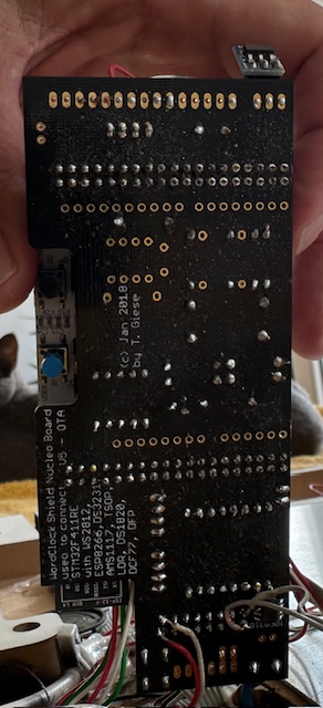
Bild
(c) Jan 2018 by T. Giese
used to connect: Nucleo Board
U5
with WS 2812 B , DS3231,
ESP8266, DS18B 20,
AMS1117, DS1820,
DCF77, DFROBOT
in
„WordClock mit WS2812“
·
Projekte & Code
·
17.07.2025 12:11
·
Platinenfotos
pixel type flags, add together as needed: // NEO_KHZ800 800 KHz bitstream (most NeoPixel products w/WS 2812 LEDs) // NEO_KHZ400 400 KHz (classic 'v1' (not v2) FLORA pixels, WS 2811 drivers) // NEO_GRB Pixels are wired for GRB bitstream (most NeoPixel products) // NEO_RGB Pixels are wired for RGB bitstream
in
„Auswahl zweier Arduino Sketches“
·
Mikrocontroller und Digitale Elektronik
·
02.12.2014 22:01
DQ28C64/C64A DQ28C65 DQ28HC256 DQ28HC64/H DQ38C16 DQ38C32 DQ47F010 DQ47F512 DQ48F010 DQ48F512 DQ52B 13/B 13H DQ52B 33/B 33H DQ5516A(AH) DQ5517A DQM28C010 DQM28C010A <<SEIKO>> S2812 A S2817A S2840R/A S2860A S2864A S28F512A <<SGS-THOMSON>> M28C64C M28F/V101/A/B M28F/V201/A *M28F/V410M *M28F/V410N *M28F/V411N
in
„PROM programmieren“
·
Mikrocontroller und Digitale Elektronik
·
06.03.2023 09:56
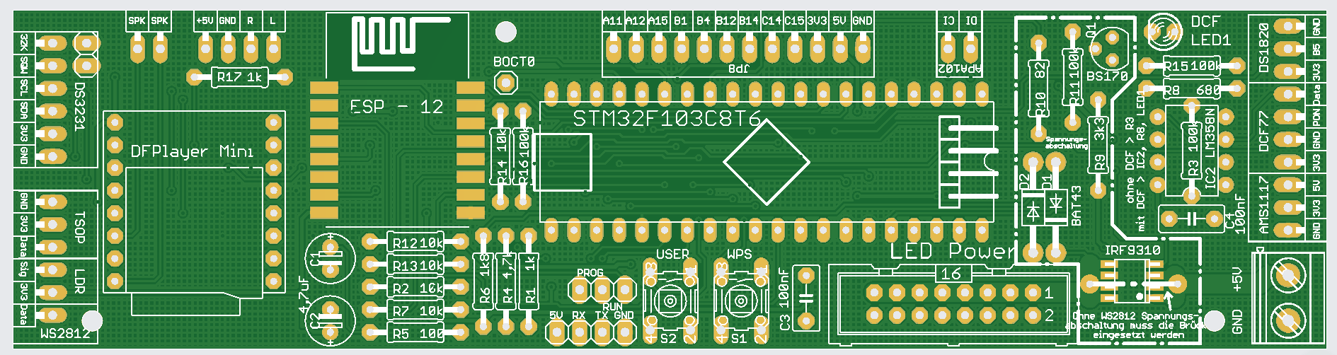
Bild
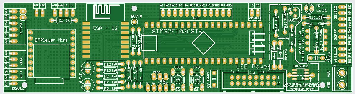
SPK SPK +5V GND R L BOCT0 R17 1k ESP - 12 STM32F103C8T6 A11 A12 A15 B 1 B 12 B 14 C14 C15 3V5 GND IC IO Q1 DCF LED1 DS1820 R15 100R 28 68 GND PIN 3V5 DS1820 R10 82 BS170 Q2 IC2 LM358 R9 3k R8 LED DCF 100nF R3 100R IC2 R2 10k R14 10k R16 100R R12 10k R13 10k R2 16k R4 4.7uF
in
„WordClock mit WS2812“
·
Projekte & Code
·
30.04.2025 10:59
·
Layouts
Bild
WS 2812 B
in
„WordClock mit WS2812“
·
Projekte & Code
·
18.05.2026 19:27
·
Fotos
Bild
-17 D6802 407 179 0501 ZENER DIODE UDZ6.2B -TE-17 405 015 8902 TR 2SC2812 -L7-TB D6803 407 179 0501 ZENER DIODE UDZ6.2B -TE-17 405 163 1602 TR 2SC2812 N-L6-TB0 D6804 407 179 0501 ZENER DIODE UDZ6.2B -TE-17 405 163 1701 TR 2SC2812 N-L7-TB0 D6831 407
in
„Sanyo LCD Beamer PLC- XU30 defekt“
·
Analoge Elektronik und Schaltungstechnik
·
20.02.2022 14:51
Bild
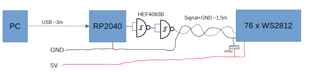
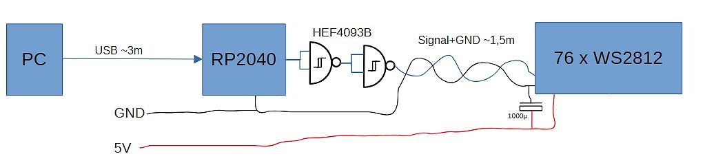
PC USB ~3m RP2040 HEF4093B Signal+GND ~1,5m 76 x WS 2812 GND 1000µ 5V
in
„PC-USB --> RP2040 --> WS2812: Kabellänge“
·
Analoge Elektronik und Schaltungstechnik
·
20.04.2026 21:14
·
Diagramme
Bild
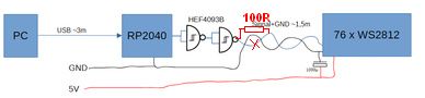
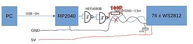
PC USB ~3m RP2040 HEF4093B 100R Signal+GND ~1.5m 76 x WS 2812 GND 100nF 5V
in
„PC-USB --> RP2040 --> WS2812: Kabellänge“
·
Analoge Elektronik und Schaltungstechnik
·
20.04.2026 22:44
·
Diagramme
2,2 – 3,3 – 4,7 – 6,8 LED Sortiment rot, grün, gelb, blau, weiß in 3mm und 5mm 1-2x LED-Streifen: WS 2801B (Achtung: Unterschiedliche Anzahl LEDs pro Meter) 1-2x LED-Streifen: WS 2812 B (Achtung: Unterschiedliche Anzahl LEDs pro Meter) 10x Siebensegment-Anzeige * alle Elemente in Through the Hole und in
in
„Einkaufsliste für die Einrichtung eines Elektronik-Labors“
·
Mikrocontroller und Digitale Elektronik
·
15.04.2017 17:14
Bild
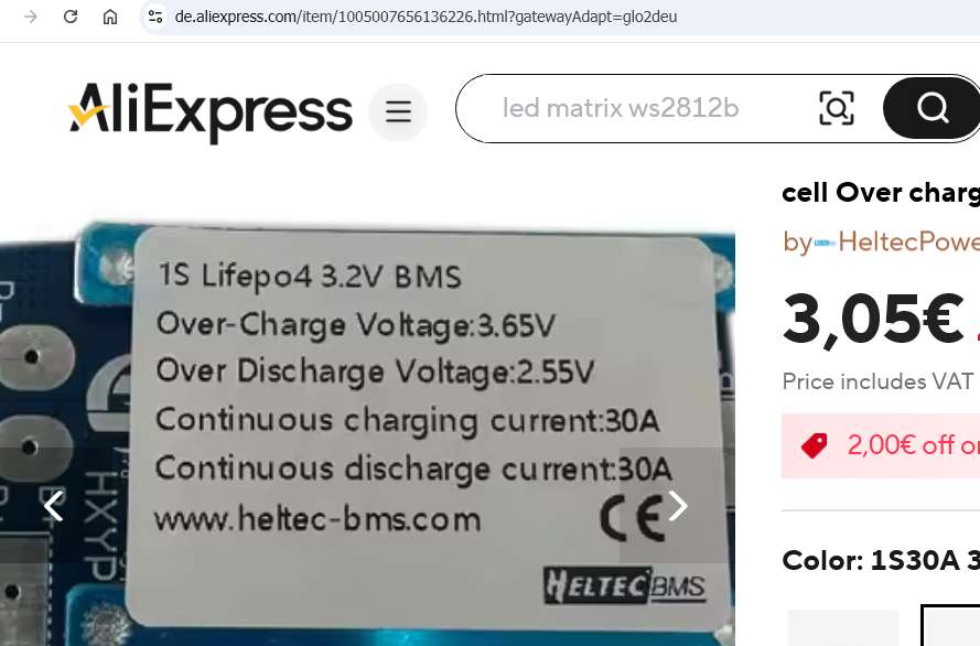
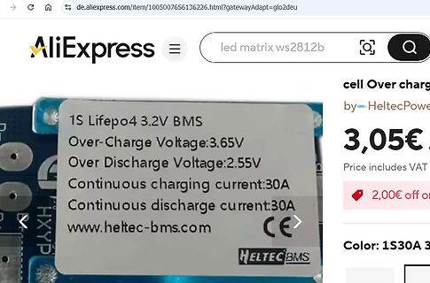
AliExpress led matrix ws 2812 b 1S Lifepo4 3.2V BMS Over-Charge Voltage:3.65V Over Discharge Voltage:2.55V Continuous charging current:30A Continuous discharge current:30A www.heltec-bms.com CE HELTEC BMS 3,05€ Price includes
in
„4s LiFePO4: Schutzschaltung (BMS) mit 3,0V/3,5V gesucht“
·
Analoge Elektronik und Schaltungstechnik
·
04.08.2025 20:26
·
Screenshots
Bild
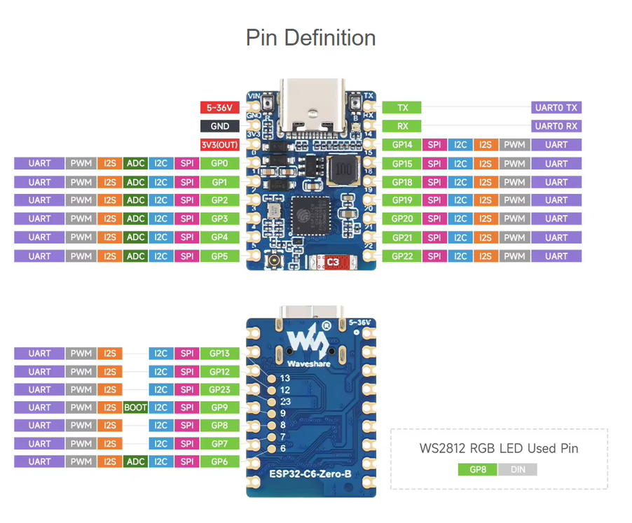
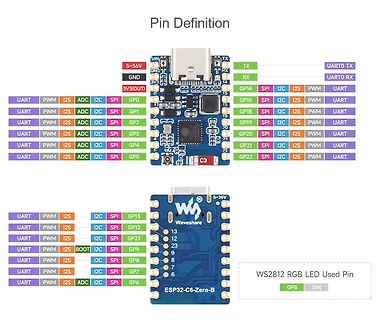
UARTO RX
3V3(OUT) SPI I2C PWM
GP0 GP1 GP2 GP3 GP4 GP5
GP12 GP13 GP23 GP9 GP8 GP7 GP6
ESP32-C6-Zero-B
WS 2812 RGB LED Used Pin
GP8 DIN
in
„Arduino Uno Q-Preiserhöhung, Mikrocontroller mit Klasse D-Verstärker, OnSemi X Synaptics uvam“
·
Mikrocontroller und Digitale Elektronik
·
30.06.2026 23:10
·
Screenshots
Bild
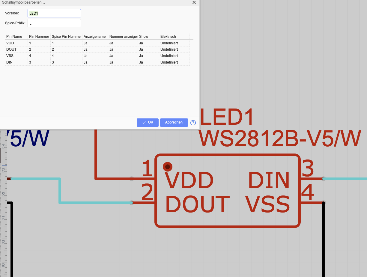
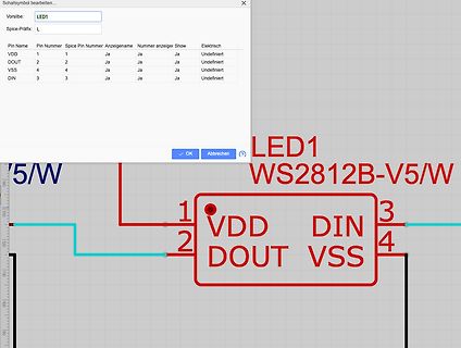
2 Ja Ja Ja Undefiniert VSS 4 4 Ja Ja Ja Undefiniert DIN 3 3 Ja Ja Ja Undefiniert OK Abbrechen LED1 WS 2812 B -V5/W 1 VDD 3 2 DOUT DIN 4 VSS
in
„Platine mit LEDs (WS2812B V5) funktionert nicht“
·
Platinen
·
11.05.2023 15:23
·
Screenshots
1 2 3 4 5 6 D D VCC R4 1 C5 LED1 Messfläche 100pF C L1 C 100uH WS -2812 -5 D t D N o D i VCC VCC G D V D VCC C4 1 2 3 4 R7 100nF GND +C1 D1 + C2 10K T1 2200uF 1N4007 100uF GNDVCC GND R5 IRLR8743PbF D2 R2 GND 4V7 100 4K7 IC1 GND GND R3 1 30 100 GND BT1 2 D1/Tx Vin 29
in
„Alibaba: Goldmünzen mit Wolframkern“
·
Offtopic
·
17.10.2017 19:13
Bild
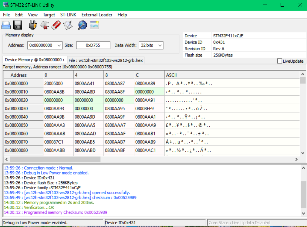
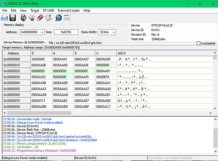
Address: 0x08000000 Size: 0xD755 Data Width: 32 bits
Device Memory @ 0x08000000 File: [wc12h-stm32f103-ws 2812 -grb.hex]
0x08000000 20050000 0800AA41 0800AA87 0800AA89
0x08000100 0800AA8B 0800AA8D 0800AA8F 00000000
0x08000200 00000000 00000000 00000000 0800AA91
0x08000300 0800AA93 00000000 08008EF9
0x08000400 0800AA9B 0800AA9D 0800AA9F 0800AA1
0x08000500 0800AAa3 0800AA5 0800AA7 0800AA9
0x08000600 0800AAAB 0800AAAD 0800AAAF 0800AB1
0x08000700 080087C1 0800AB5 0800AB7 0800AB9
0x08000800 0800AABB 0800AABD 0800ABBF 0800AAC1
in
„WordClock mit WS2812“
·
Projekte & Code
·
23.08.2025 14:58
·
Screenshots
Bild
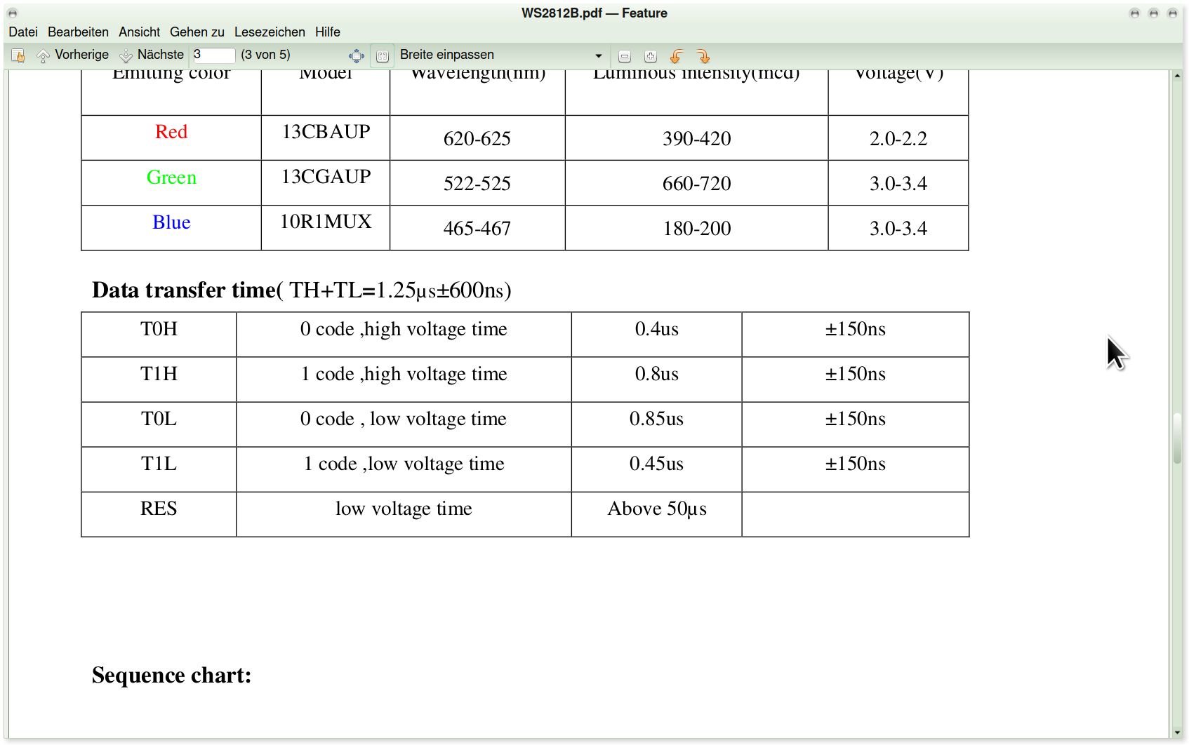
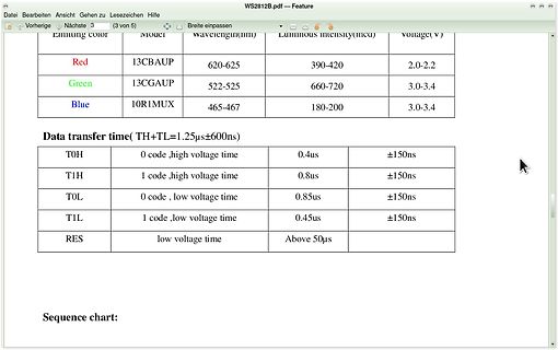
WS 2812 B .pdf - Feature
Red 13CBAUP 620-625 390-420 2.0-2.2
Green 13CGAUP 522-525 660-720 3.0-3.4
Blue 10R1MUX 465-467 180-200 3.0-3.4
Data transfer time( TH+TL=1.25µs±600ns)
T0H 0 code, high voltage time
in
„RGB Led Band von Action“
·
Mikrocontroller und Digitale Elektronik
·
29.11.2025 13:56
·
Screenshots
Bild
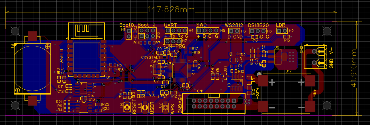
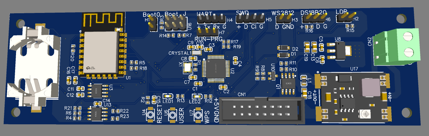
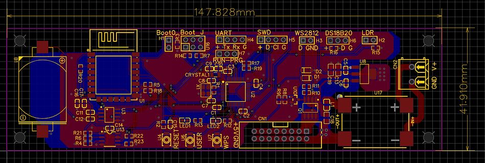
147.828mm 41.910mm Boot0 Boot J UART H4 H5 H3 H6 H2 SWD D C I G D GND D G LDR WS 2812 DS18B 20 R14 R7 R15 R20 C7 C16 R5 R18 U1 CRYSTAL C8 C9 C3 R17 R19 C11 C12 C14 U3 R21 R6 R4 R22 R23 U13 LED1 R13 LED2 R2 R12 C1 C2 C18 U4 RESET U6 USER U7 WPS 5V GND CN1 CN2 U2 U17 GND V+
in
„WordClock mit WS2812“
·
Projekte & Code
·
16.04.2025 07:59
·
Layouts
Flashen des STM32MiniBoards Benötigt werden neben dem STM32MiniBoard: Hardware: ST-Link V2 (z. B . von AliExpress oder ebay) Software: ST-Link/V2 , siehe: http://www.st.com/en/development-tools/st-link-v2.html Installation der ST-Link/V2-Software: https://www.youtube.com/watch?v=ONzRL06Umfo Danach
in
„WordClock mit WS2812“
·
Projekte & Code
·
17.03.2017 17:05
Bild
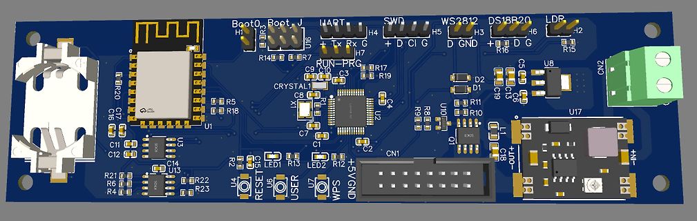
Boot0, Boot J, HART, SWD, WS 2812 , DS18B 20, LDP, H1, H4, H5, H3, H2, U16, R14, R7, R17, R19, R15, R16, D, C, I, G, GND, U8, C5, C15, C19, D2, D1, C16, R20, C7, C9, C10, C3, C8, LX, U2, C4, U1, R5, R18, R8, R9, U10, R11, R10, C6,
in
„WordClock mit WS2812“
·
Projekte & Code
·
16.04.2025 08:00
·
Layouts
Bild
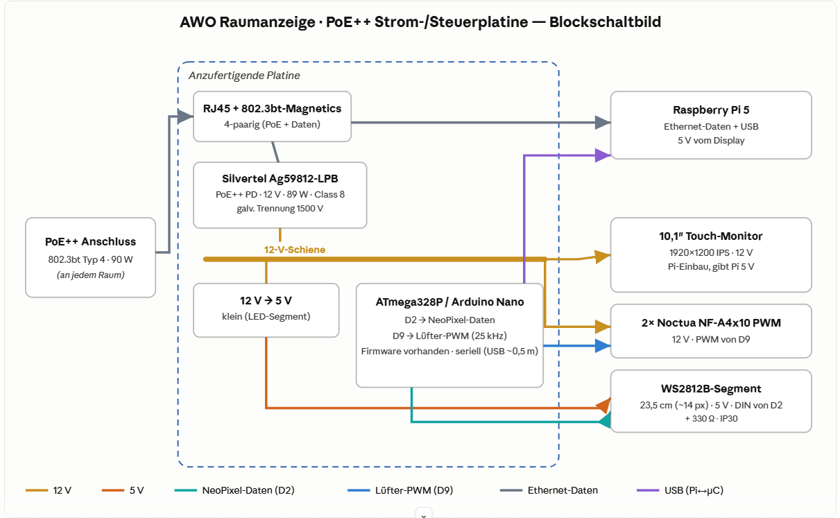
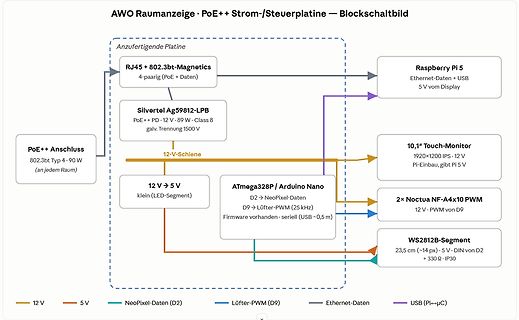
Lüfter-PWM (25 kHz)
Firmware vorhanden · seriell (USB ~0,5 m)
2x Noctua NF-A4x10 PWM
12 V · PWM von D9
WS 2812 B -Segment
23,5 cm (~14 px) · 5 V · DIN von D2
+ 330 Ω · IP30
12 V
5 V
NeoPixel-Daten (D2)
Lüfter-PWM (D9)
Ethernet-Daten
USB (Pi->µC)
in
„Projekt AWO-Raumanzeige — Hilfe/Umsetzung einer PoE++ Strom- & Steuerplatine gesucht (Raspberry Pi)“
·
Platinen
·
14.06.2026 18:38
·
Diagramme
/* a LED driver, knight rider style drives a string of intelligent LEDs (WS 2812 B ) speed setting via voltage on analog input */ #include <Adafruit_NeoPixel.h> #define LED_CNT 30 #define LED_PIN 22 #define POTI_PIN A0 Adafruit_NeoPixel pixels(LED_CNT, LED_PIN, NEO_GRB + NEO_KHZ800
in
„LED-Lauflicht im Knight Rider Style“
·
Projekte & Code
·
15.12.2020 17:00
LED - Spielbrett mit WS 2812 B 144 LED /m Lageplan der Bauteile 32 33 34 35 36 + + 31 + 7 6 0 3 11 5 3 + 8 + 8 3 12 + 29 2 + 9 + 28 4 + e 7 40 S Zi 4 27 p 3 6 1 l er 2 5 + 1 1 iel r2 Sp 10 2 8 9 6 + 4 3 + + 7 + + 4 5 2 1 25 26
in
„Gefräste Platine rationell mit LED 's bestücken“
·
Platinen
·
30.12.2017 17:12
12V_Rel LM393D R75 6N138 +3V3 PC5 PD2 M6 PD2 +12V R24 LM393D 2M (nb) ) PC6 M4 PC6 PC2 Ofen_TA1 SS34 PIS2812 10uH + µ n TRIAC1 IC8 ( 7 9 2 1 470/1W R26 8 K PC7 M8 PC7 PC3 Ofen_TA2 D C 2 7 C 820 IC6b R36 nc Vcc 3 0 GND C R 10K (nb) R 1 Vf+ VB P6SMB18CA nb Vf- VO T_ISign BTA16/600B R76 nc GND GND Laderegler
in
„Heizungssteurung im Eigenbau“
·
Mikrocontroller und Digitale Elektronik
·
16.01.2010 18:53
util/delay.h> #include <avr/interrupt.h> #include <avr/io.h> #include <avr/sleep.h> #include "light_ws 2812 .h" #include "config.h" #include "debounce.h" #include "led_modes.h" volatile uint8_t sys_tick = 0u; ISR( TIMER0_OVF_vect ) // every 10ms { TCNT0 = (uint8_t)(int16_t)-(F_CPU / 1024 * 10e-3 + 0.5);
in
„Code zu groß für AtTiny45“
·
Mikrocontroller und Digitale Elektronik
·
07.07.2016 15:00
Bild
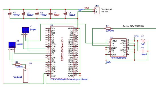
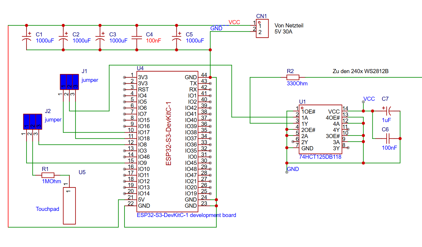
1000uF C3 1000uF C4 100nF C5 1000uF CN1 1 2 VCC GND 5V 30A J1 jumper J2 jumper R2 330Ohm Zu den 240x WS 2812 B U4 ESP32-S3-DevKitC-1 1 3V3 2 3V3 3 RST 4 IO4 5 IO5 6 IO6 7 IO7 8 IO5 9 IO6 10 IO7 11 IO8 12 IO8 13 IO4 14 IO5 15 IO9 16 IO10 17 IO11 18 IO12 19 IO13 20 IO14 21 5V 22 GND 44 GND 43 TX 42 RX 41 IO
in
„ESP32 und 240Stück WS2812B“
·
Mikrocontroller und Digitale Elektronik
·
23.12.2025 17:04
·
Schaltpläne
<avr/sleep.h> #include "includes/config.h" #include "includes/debounce.h" #include "includes/light_ws 2812 .h" #include "includes/led_modes.h" volatile uint8_t sys_tick = 0u; ISR( TIMER0_OVF_vect ) // every 10ms { TCNT0 = (uint8_t)(int16_t)-(F_CPU / 1024 * 10e-3 + 0.5); // preload for 10ms sys_tick = 1u
in
„Code zu groß für AtTiny45“
·
Mikrocontroller und Digitale Elektronik
·
07.07.2016 12:56
3 SCL 3 OS GND 8 NEOPIX VCC VEXTOUT D HDR-M-2.54_1x1 4 4 4 SDA R7 GND D 1 10K LED1 GND VCC WS 2812 B R470 1 4 2 VDD DIN 3 Neopix DOUT VSS GND GND VCC P1 STLINK connector 1 VCC 2 GND 3 SWCLK 4 SWDIO E 5 VCC-T E 6 RSTn C5 C6 100nF 10uF S S D C A L C4 100nF R10 R9 100k 100k JP1 U1 GND PINHD-1X12-CB
in
„STM32 Lora Platine Entwurf“
·
Platinen
·
27.02.2021 08:39

 Bild
Bild
 Bild
Bild
 Bild
Bild
 Bild
Bild
 Bild
Bild
 Bild
Bild

 Bild
Bild
 Bild
Bild
 Bild
Bild
 Bild
Bild
 Bild
Bild
 Bild
Bild
 Bild
Bild
 Bild
Bild
 Bild
Bild
 Bild
Bild
 Bild
Bild
 Bild
Bild