-
PDF
LED-Matrix.pdf
4 D L 1 2 3 4 5 6 7 8 D 7 Q Q Q Q Q Q Q G U I I I I I I I I G 4 Änderungen Datum Name Bezeichnung LED-Matrix Blattzahl: gez.: 19.03.2007 Peter Zirngibl 1 Datum Name gepr.: Blatt-Nr.: Zeichnungs-Nr.: 1
in „LED-Matrix Ansteuerung“ · Mikrocontroller und Digitale Elektronik ·
-
PDF
led_matrix.pdf
C V T1 BC847 R1 R19 T2 BC847 R2 R18 T3 BC847 R3 R17 T4 BC847 R4 R16 T5 BC847 R5 LED1 TA20-11HWA R15 2 T6 7 R7 1 R6 BC847 5 R5 R6 R4 8 R3 R14 14 R2 9 R1 T7 12 R4 BC847 3 1 2 3 4 5 R7 C C C C C C 1 1 3 4 16 R13 T8 BC847 R8 T9 BC847 R9 T10 BC847 R10 T11 BC847 R11 T12 BC847 R12 GND
in „LED Dot Matrix richtig anschließen“ · Mikrocontroller und Digitale Elektronik ·
-
PDF
led_matrix.pdf
C V T1 BC847 R1 R19 T2 BC847 R2 R18 T3 BC847 R3 R17 T4 BC847 R4 R16 T5 BC847 R5 LED1 TA20-11HWA R15 2 T6 7 R7 1 R6 BC847 5 R5 R6 R4 8 R3 R14 14 R2 9 R1 T7 12 R4 BC847 3 1 2 3 4 5 R7 C C C C C C 1 1 3 4 16 R13 T8 BC847 R8 T9 BC847 R9 T10 BC847 R10 T11 BC847 R11 T12 BC847 R12 GND
in „LED Dot Matrix richtig anschließen“ · Mikrocontroller und Digitale Elektronik ·
-
Datei
avr-usb-162_Led.c
Ausgang; Low_LED_Matrix[8] = Matrix_K2_low; High_LED_Matrix[8] = Matrix_A3_Ausgang; Low_LED_Matrix[9] = Matrix_K2_low; High_LED_Matrix[9] = Matrix_A4_Ausgang; Low_LED_Matrix[10] = Matrix_K2_low; High_LED_Matrix[10]=
in „Zeitabstand 8 mal größer als erwartet“ · Mikrocontroller und Digitale Elektronik ·
-
Datei
matrix.c
,hue); } } void set_row_hue(uint16_t hue, uint8_t row){ uint8_t i; for (i=0;i<columns;i++){ set_led_hue(row,i,hue); } } //sets the whole matrix to a RGB colour void set_matrix_rgb(uint16_t red, uint16_t green, uint16_t blue) { uint8_t ctr1; uint8_t ctr2; for (ctr2 = 0; ctr2 < rows; ctr2++) { for (
in „7x7 RGB-LED matrix problem“ · Mikrocontroller und Digitale Elektronik ·
-
PDF
Comparison_of_simple_LED_circuits_for_low_power_LEDs.pdf
module homogeneity. Matrix circuit with one resistor for the complete circuit. As the simulation in Figure 7 shows the forward current for the LEDs with the typical forward voltage is 35.3 mA (~ 35 mA). For the LEDs from the
in „led-tech.de: Wieso parallel verschaltete LEDs?“ · Analoge Elektronik und Schaltungstechnik ·
-
Datei
matrix.c
/* * matrix.c * * Created: 27.11.2014 12:24:33 * Author: Prophecy */ #include <avr/io.h> #include "main.h" #include "global.h" #include "matrix.h" /* void clr_matrix_data(void){ for (uint8_t i=0; i < BAM_BITS;
in „[avr-gcc]7x7 RGB matrix code problem“ · Mikrocontroller und Digitale Elektronik ·
-
Datei
matrix.c
/* * matrix.c * * Created: 27.11.2014 12:24:33 * Author: Prophecy */ #include <avr/io.h> #include "main.h" #include "global.h" void clr_matrix_data(void){ for (uint8_t i=0; i < BAM_BITS; i++){ for (uint8_t r=0
in „7x7 RGB-LED matrix problem“ · Mikrocontroller und Digitale Elektronik ·
-
 Bild
Bild
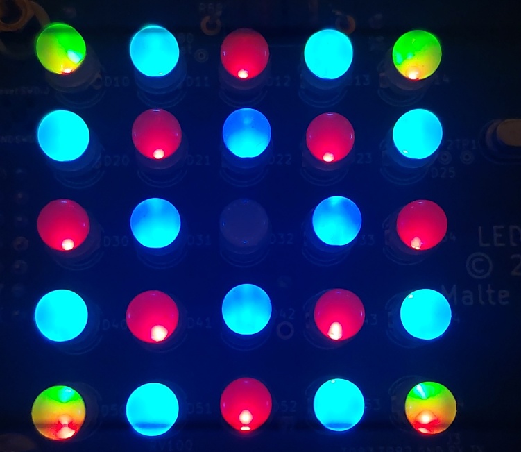
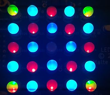
Leuchtende LEDs auf einer Leiterplatte
D10 D11 D12 D13 D15 D20 D21 D22 D25 D30 D31 D32 D33 D40 D41 D42 D50 D51 D52
in „LED Matrix Ansteuerung mit STM32F4 ohne CPU Last“ · Projekte & Code · · Platinenfotos
-
 Bild
Bild
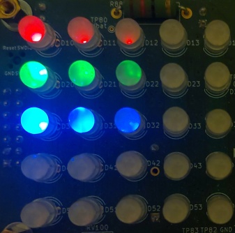
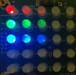
Leuchtende LEDs auf einer Leiterplatte
Reset SWD10 TP80 bat D12 D13 GND5 CD20 CD21 D22 D23 CD30 CD31 CD32 D32 CD40 CD41 CD42 D43 CD50 CD51 D52 D53 RV10Q TP83 TP82 GND
in „LED Matrix Ansteuerung mit STM32F4 ohne CPU Last“ · Projekte & Code · · Platinenfotos
-
Datei
FastLED_LPD8806.patch
-15,7 +13,8 @@ LEDMatrix::~LEDMatrix() { } void LEDMatrix::init() { - matrix.begin(); + FastLED.addLeds<LPD8806, PIN_DATA, PIN_CLOCK, RGB>(leds, + sizeof(leds) / sizeof(leds[0])); } void LEDMatrix::clear() { @@ -64,36 +63,28 @@ void LEDMatrix::update() { float calibrationGreenEffectively
in „SmartLEDLamp/Mood Light (IKEA Vidja-Korpus + WS2801 Stripes + ESP8266)“ · Projekte & Code ·
-
PDF
LED-Matrix-Controller.pdf
www.austriamicrosystems.com Revision 2.24 15 - 20 AS1106, AS1107 Data Sheet - Typical Application 8x8 LED Dot Matrix Driver The application example in Figure 14 shows the AS1106 as an 8x8 LED dot matrix driver. The LED columns have common cathodes and are connected to the DIG0:7 outputs. The rows are connected
in „Gleich mehrfach ins Knie geschossen“ · Mikrocontroller und Digitale Elektronik ·
-
Datei
LED_Matrix_Fehler.ino
int a=1,b=0,c=0,d=0,e=0,f=0,g=0,h=0; int input=0; #define display_array_size 8 #define data_null 0x00, 0x00, 0x00, 0x00, 0x00, 0x00, 0x00, 0x00 // null char #define data_ascii_A1 a,b,c,d,e,f,g,h /** **"A" #define A { // {0, 0, 0, 0, 0, 0, 1, 0}, //0x02 {0, 0, 0, 0, 1, 1, 0, 0}, //0x0C {0, 0, 0, 1, 1, 0, 0, 0}, //0x18 {0, 1, 1, 0, 1, 0, 0, 0}, //0x68 {0, 1, 1, 0, 1, 0, 0, 0}, //0x68 {0, 0, 0, 1, 1, 0, 0, 0}, //0x18 {0, 0, 0, 0, 1, 1, 0, 0}, //0x0C {0, 0, 0, 0, 0, 0, 1, 0} //0x02 } **/ byte data_ascii[][display_array_size] = { data_null, data_ascii_A1 }; const int row1 = 2; // the number of the
in „Definieren von variable im laufenden Programm“ · Softwareentwicklung ·
-
Datei
LED_Matrix_Original.ino
LED_Matrix_Original.ino
in „Definieren von variable im laufenden Programm“ · Softwareentwicklung ·
-
Datei
LED_Matrix_Fehler.ino
unsigned int input=0; unsigned int in; unsigned int a[8]; #define display_array_size 8 #define data_null 0x00, 0x00, 0x00, 0x00, 0x00, 0x00, 0x00, 0x00 // null char byte data_ascii[][display_array_size] = { data_null, {a[0],a[1],a[2],a[3],a[4],a[5],a[6],a[7]} }; const int row1 = 2; // the number of the row pin 24 const int row2 = 3; // the number of the row pin 23 const int row3 = 4; // the number of the row pin 22 const int row4 = 5; // the number of the row pin 21 const int row5 = 17; // the number of the row pin 4 const int row6 = 16; // the number of the row pin 3 const int row7 = 15; // the
in „2 stellige Zahl Seriell übertragen“ · Mikrocontroller und Digitale Elektronik ·
-
PDF
AN040_Comparison_of_simple_LED_circuits_for_low_power_LEDs.pdf
module homogeneity. Matrix circuit with one resistor for the complete circuit. As the simulation in Figure 7 shows the forward current for the LEDs with the typical forward voltage is 35.3 mA (~ 35 mA). For the LEDs from the
in „LED-Taschenlampe "cree" XHP70.2“ · Mikrocontroller und Digitale Elektronik ·
-
PDF
AN040_Comparison_of_simple_LED_circuits_for_low_power_LEDs.pdf
module homogeneity. Matrix circuit with one resistor for the complete circuit. As the simulation in Figure 7 shows the forward current for the LEDs with the typical forward voltage is 35.3 mA (~ 35 mA). For the LEDs from the
in „LED Gesamtstrom stimmt irgendwie nicht“ · Analoge Elektronik und Schaltungstechnik ·
-
PDF
LED-Dot.pdf
AgilentHDSP-B571/B573 DotMatrixDisplays Data Sheet Features • 5 x 7 dot matrix • Dot diameter 5.0 mm • Dot pitch 7.62 mm • Bi-color capability 5 x 7 Bi-Color General Purpose Dot Matrix • Choice of two colors Green Displays 53.2 mm
in „V : Grosse LED Dot-Matrix Anzeigen 5mm Leuchtpunkt DUO !!“ · Markt ·
-
Datei
scroll.c
scrollString(char *string, int speed); static void scrollIn(char token, int speed); static void allLedsOff(void); static void shiftLedsLeft(void); static void setLed(char x, char y, char onOff); static char getLed(char x, char y); #define MATRIX_HEIGHT 16 #define MATRIX_WIDTH 16 #define MATRIX_SIZE_BYTES (MATRIX_HEIGHT * (MATRIX_WIDTH >> 3)) #define FONT_WIDTH 8 #define KERNING 2 /* LED Anzeige */ static unsigned char LEDS[MATRIX_HEIGHT * (MATRIX_WIDTH >> 3)]; /* *************** CODE ZUM TESTEN ***********
in „Laufschrift auf LED Matrix“ · Mikrocontroller und Digitale Elektronik ·
-
PDF
ha0136ev110.pdf
Driving Matrix LEDs Using the HT1632C to Display anAnimated Figure Driving Matrix LEDs Using the HT1632C to Display an Animated Figure D/N: HA0136E Introduction The HT1632C is a memory mapping type of LED display
in „8x8 RGB Matrix Ansteuerungsproblem“ · Mikrocontroller und Digitale Elektronik ·
-
PDF
LED_Matrix_Controller_V5.pdf
einzelnen oder weniger Einzelmodule zum Eigenbau eines sehr dekorativen und technisch sehr universellem Matrix Displays mit 64x64 einzeln steuerbaren RGB LEDs. Solche Einzelmodule gibt es in verschiedenen mechanischen Abmessungen, wobei die Anzahl der LEDs gleichbleibt, jedoch der Abstand variiert. Gängige
in „Universeller 64x64 LED-Matrix Controller“ · Projekte & Code ·
-
Datei
TextWithArduinoGraphics_RTC_Fertig_ohne_Serial.print.ino
// Begin Led-Matrix #include "ArduinoGraphics.h" #include "Arduino_LED_Matrix.h" ArduinoLEDMatrix matrix; //End Led-Matrix //Begin RTC #include "RTClib.h" RTC_DS3231 rtc; char daysOfTheWeek[7][12] = { "Sonntag",
in „RTC DS3231 (EOSC) Uhrzeit läuft nicht weiter, nur mit Knopfzelle“ · Mikrocontroller und Digitale Elektronik ·
-
Datei
tools.c
datastream[BytePos],bitPos,0); } } } /* Füllt alle Datenbereiche 0..7 aller 12 Module auf */ void DisplayMatrix() { int datacnt = DATA_SETS-1; for (int digit = 0; digit < 8; digit++) { CE_LOW(); for (int i = 0; i < LED_MODULE_MAX; i++) SPI_SendWord(((uint16_t)(MAX7219_DIGIT_0 + digit) << 8) | datastream[datacnt
in „STM32F1xx: Wie GOL am "Leben" halten?“ · Mikrocontroller und Digitale Elektronik ·
-
 Bild
Bild
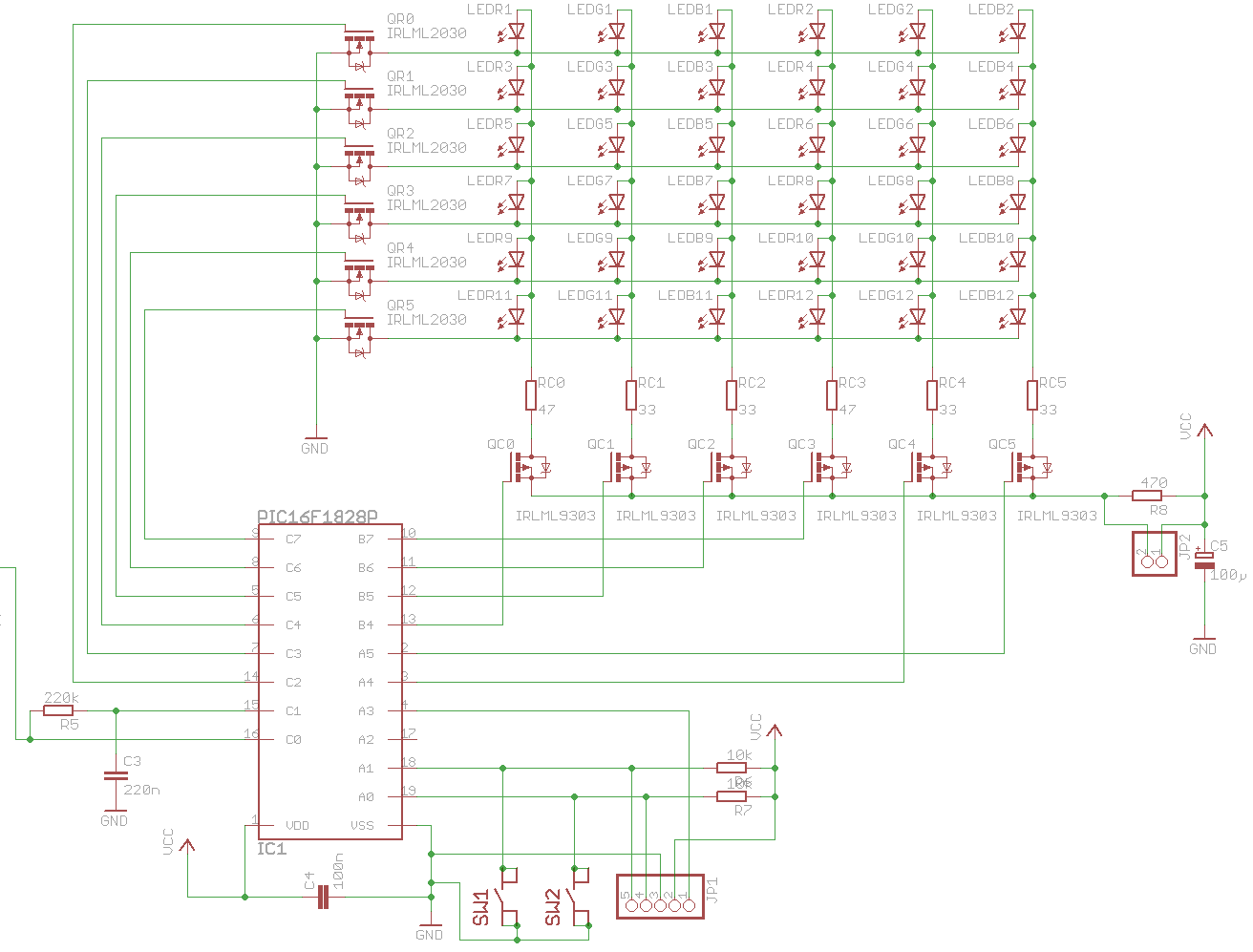
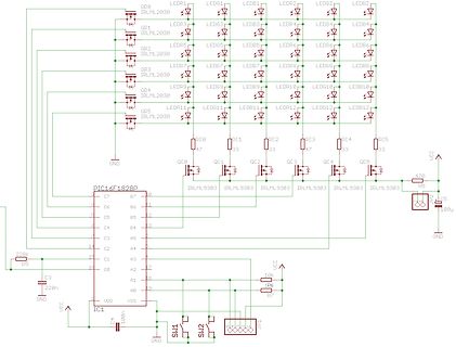
Schaltplan mit PIC16F1828P und LED-Ansteuerung
QR0 IRLML2030, LEDR1, LEDG1, LEDB1, LEDR2, LEDG2, LEDB2, QR1 IRLML2030, LEDR3, LEDG3, LEDB3, LEDR4, LEDG4, LEDB4, LEDR5, LEDG5, LEDB5, LEDR6, LEDG6, LEDB6, QR2 IRLML2030, LEDR7, LEDG7, LEDB7, LEDR8, LEDG8, LEDB8, QR3 IRLML2030, LEDR9, LEDG9, LEDB9, LEDR10, LEDG10, LEDB10, QR4 IRLML2030, LEDR11, LEDG11, LEDB11, LEDR12, LEDG12, LEDB12, QR5 IRLML2030, QC0 47, QC1 33, QC2 47, QC3 33, QC4 33, QC5 33, GND, PIC16F1828P, C7 bis C0, A7 bis A0, VSS, VDD, UCC, GND, SW1, SW2, QC1 IRLML9303, QC2 IRLML9303, QC3 IRLML9303, QC4 IRLML9303, QC5 IRLML9303, R8 170, C5 100µ, R7 10k, 10k, R6 220k, C3 220n, C4 100n
in „LED-Matrix - Problem mit "Nachleuchten"“ · Mikrocontroller und Digitale Elektronik · · Schaltpläne
-
PDF
Comparison_of_LED_circuits.pdf
, application. characterize and comment on LED behavior and failure modes in serial and matrix Exemplary voltage groups of the Power circuits. TOPLED LA E67B (which will be used in the simulations to follow) are shown below: Failure modes of LEDs
in „LED's so beschalten?“ · Mikrocontroller und Digitale Elektronik ·
-
Datei
tools.c
(); DisplayMatrix(); } /* Init Matrix LED */ void InitMatrix() { /* Decode Mode ausschalten */ for (int i = 0; i < LED_MODULE_MAX; i++) { CE_LOW(); SPI_SendWord((uint16_t)(MAX7219_DECODE_MODE << 8) + 0); CE_HIGH();
in „Umgang mit globalen Datenstrukturen“ · Mikrocontroller und Digitale Elektronik ·
-
Datei
tools.c
leer, dann Gleiter erzeugen */ if (cells <= 15) { LED_ON(); handofgod(10); CreateGliders(1); } if (CheckForPeriod((uint8_t*)matrix,(uint8_t*)datastream,DATA_SETS)) { if (stillcnt++ > 5) { LED_ON(); CreateGliders(2); } } else { stillcnt = 0; } /* Timer
in „Matrix indizierbar machen?“ · Mikrocontroller und Digitale Elektronik ·
-
PDF
LEDcubeProjektbeschreibung_v1.0.pdf
Lötstopplack versehen. Bild 4: Schaltplan der Steuerelektronik Bild 5: Layout der Steuerelektronik 2.5. LED-Matrix Anhand einiger Bilder soll im Folgenden der Aufbau der LED-Matrix gezeigt werden. Dabei werden zunächst die acht Ebenen einzeln aufgebaut und diese anschließend zu dem Würfel zusammenge- setzt
in „LED cube 8x8x8“ · Mikrocontroller und Digitale Elektronik ·
-
Datei
MATRIX-PICS.c
<<COL_7); } //************************************************************************ uint8_t get_led(uint8_t x, uint8_t y) { return (bit_is_set(led[y], 7-x)); } //************************************************************************ ISR(TIMER0_OVF_vect) { TCNT0 = PRELOAD_T0; // Matrix zuruecksetzen matrix_clear(); // naechste Zeile/Spalte ermitteln row++; if (row > 7) row = 0; // Spalten setzen if (get_led(0, row)) COL_0_PORT &= ~(1<<COL_0); if (get_led(1, row)) COL_1_PORT &= ~(1<<COL_1); if (get_led
in „avr-studio4 fehlrtmeldung nach neuinstallation“ · Mikrocontroller und Digitale Elektronik ·
-
 Bild
Bild
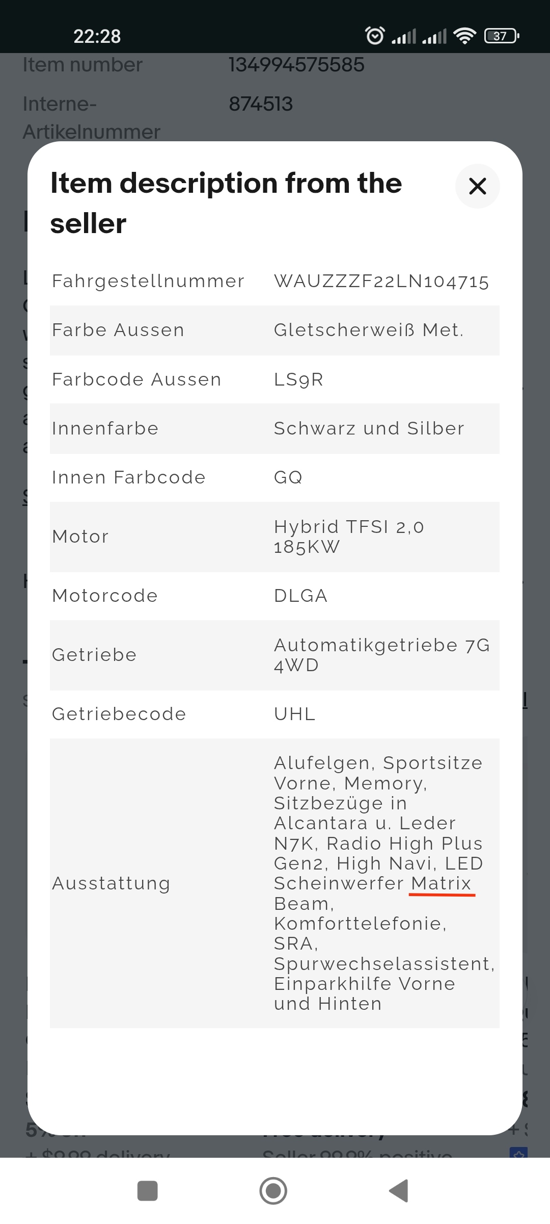
Screenshot einer Fahrzeugbeschreibung eines Verkaufsportals
4WD Getriebecode UHL Ausstattung Alufelgen, Sportsitze Vorne, Memory, Sitzbezüge in Alcantara u. Leder N7K, Radio High Plus Gen2, High Navi, LED Scheinwerfer Matrix Beam, Komforttelefonie, SRA, Spurwechselassistent, Einparkhilfe Vorne und Hinten
in „LED von Scheinwerfer oder Blinker wie ansteuern?“ · Fahrzeugelektronik · · Screenshots

-
PDF
Siemens_IntelligentDisplays1998.pdf
in High Efficiency Red and Green Dot Matrix Replacement for DL1414T. 0.145" High, Dot Matrix Character. 128 Special ASCII Characters for English, German, Italian, Swedish, Danish, and Norwe-gian Languages. Wide Viewing Angle: X Axis ±50 deg,
-
PDF
DSA0079368.pdf
LM16152E LCD Data Sheet Dot Matrix LCD Unit FEATURES • The unit consists of a dot-matrix LCD • Extensive instruction set: panel, CMOS driver LSI and backlight LED with high brightness and stable – Display clear, display ON/OFF, radiation
in „Pin Belegung LCD 1x16 Sharp LM16152“ · Mikrocontroller und Digitale Elektronik ·
-
Datei
IO-Modul04.c
eeprom_read_byte(&input_select[i])) { case 0: // Taster hat Einzelfunktion if(get_key_press(1<<i)) { LED_PORT ^= eeprom_read_byte(&output_matrix[0][i]); } break; case 1: // Taster hat Doppelfunktion if(get_key_short(1<<i)) { LED_PORT ^= eeprom_read_byte(&output_matrix[0][i]); } if(get_key_long(1<<i)) {
in „Stromausfall, Parameter speichern, eeprom.h“ · Mikrocontroller und Digitale Elektronik ·
-
Datei
lcd.c
<<COL_7); } //************************************************************************ uint8_t get_led(uint8_t x, uint8_t y) { return (bit_is_set(led[y], MATRIX_DX-1-x)); } //************************************************************************ ISR(TIMER0_OVF_vect) { TCNT0 = PRELOAD_T0; // Matrix zuruecksetzen matrix_clear(); // naechste Zeile/Spalte ermitteln row++; if (row > 7) row = 0; // Spalten setzen if (get_led(0, row)) COL_0_PORT &= ~(1<<COL_0); if (get_led(1, row)) COL_1_PORT &= ~(1<<COL_1); if (get_led
in „avr register ausläsen und umwandeln zu ascii, wie?“ · Mikrocontroller und Digitale Elektronik ·
-
Datei
main.c
led, green); set_led_blue(row, led, blue); sei(); } void set_matrix_rgb(uint8_t red, uint8_t green, uint8_t blue) { uint8_t ctr1; uint8_t ctr2; for (ctr2 = 0; ctr2 <= __max_row; ctr2++) { for (ctr1 = 0;
in „7x7 rgb led matrix mit PWM und soundsteuerung code fehlerhaft?“ · Mikrocontroller und Digitale Elektronik ·
-
PDF
DotMatrix.pdf
definierende Zeichen. 0 0 0 0 0 0 0 0 0 0 0 0 0 0 . 0 0 0 • • 0 0 • • • 0 • • • • Abbildung 93 Dot-Matrix-Anzeige TA07-11 ••••• e Dot-Matrix-Anzeige ansteuern zu können, muss die Zuordnung der 35 LEDs Abbildung 95 Zu definierendes Zeichen Anschlüssen bekannt sein. Die Innenschaltung der Dot-Matrix-Anzeige
in „Problem mit gosub in Bascom“ · Mikrocontroller und Digitale Elektronik ·
-
Datei
dot57_wuerfel.c
sei(); } // ---------------------- d57_putpixel ---------------------- // // schaltet eine einzeln LED der Matrix an, bzw. aus // // Uebergabe // x,y : Koordinate der LED in der Matrix // f : 1 = LED an, 0 = LED aus // // ---------------------------------------------------------- void d57_putpixel(char
in „LED Dot-Matrix 5x7 Mäxle-Würfelspiel / 2er Würfel“ · Mikrocontroller und Digitale Elektronik ·
-
PDF
LD3361BS.pdf
0.1msec width, for long operating life, max. of 20mA recommended (2) Reverse biasing of the dot matrix is not recommend, will cause damage to the leds Electro-optical Characteristics (Ta = 25℃) LUMINOUS MAX. INTENSITY / DICE PEAK REVERSE VF SEGMENT MATERIAL WAVELENGTH CURRENT / (V) VF (V) AVERAGE (IF
in „TPIC6B595N Cascade Problem“ · Mikrocontroller und Digitale Elektronik ·
-
PDF
LED_matrix_driver_flyer.pdf
voltages of 3.3 and 5 V and four package types simplify the design of FULL-Color and monochromatic LED panels or even for use in general applications where serial data must be transformed into LED driving. V-LED LED1 LED16 LED17 LED32 LEDn LEDn+16 STP16CD596 STP16CD596 STP16CD596 SDI SDO SDI SDO SDI
in „Grosse LED Dot-Matrix“ · Mikrocontroller und Digitale Elektronik ·
-
PDF
VQC10_LED_Matrix.pdf
Mittwoch, 17. Juni 2009 21:03 #include <avr/io.h> unsigned char text[] = {0xff, 0xff, 0xff, 0xff, 0xff, 0x01, 0x02, 0x04, 0x08, 0x10, 0x01, 0x02, 0x04, 0x08, 0x10, 0x11, 0x22, 0x44, 0x88, 0x1f}; #define SER_HIGH PORTD |= (1<<5) #define SER_LOW PORTD &= ~(1<<5) #define SCLK_HIGH PORTD |= (1<<4) #define SCLK_LOW PORTD &= ~(1<<4) #define RCK_HIGH PORTD |= (1<<3) #define RCK_LOW PORTD &= ~(1<<3) #define EN_HIGH PORTD |= (1<<2) #define EN_LOW PORTD &= ~(1<<2) #define ZEN_HIGH PORTD |= (1<<6) #define ZEN_LOW PORTD &= ~(1<<6) int main() { unsigned char x=0; unsigned char y=0; unsigned char z=0; volatile
in „Mega8: VQC10 LED-Matrix 5x7 Zeitmultiplex - Bestimmte Bits eines unsigned char auf Ports ausgeben“ · Mikrocontroller und Digitale Elektronik ·
-
PDF
AS1130_Datasheet_EN_v5__1_.pdf
via an I²C compatible interface. Open and Shorted LED Error Detection The AS1130 offers a 12x11 LED Matrix with 1/12 cycle rate. The 132 LEDs in Dot Matrix required lines to drive all 132 LEDs are reduced to 12 by using the Low Power Shutdown Current cross
-
PDF
Dot-Matrix-Driver_max6952eax.pdf
1; 10/02 N K IT V A L U A TIO E A IL A B L E A V 4-Wire Interfaced, 2.7V to 5.5V, 4-Digit 5 ✕ 7 Matrix LED Display Driver M General Description Features The MAX6952 is a compact cathode-row display driver High-Speed 26MHz with SPI-/QSPI-™/ A that interfaces microprocessors to 5 ✕ 7 dot-matrix LED MICROWIRE
in „PIC: max6952 ansteuerung über SPI“ · Mikrocontroller und Digitale Elektronik ·
-
PDF
MAX6953.pdf
19-2312; Rev 3; 3/04 2-Wire Interfaced, 2.7V to 5.5V, 4-Digit 5 ✕ 7 Matrix LED Display Driver M General Description Features 2 A The MAX6953 is a compact cathode-row display driver ♦ 400kbps 2-Wire Interface Compatible with I C that interfaces microprocessors to 5 ✕ 7 dot-matrix LED X 2 ♦ 2.7V to 5.5V Operation displays through an I C™-compatible serial interface. The MAX6953 drives up to four digits (140 LEDs). ♦ Drives 4 Monocolor or 2 Bicolor Cathode-Row 6 5 ✕ 7 Matrix Displays
in „Master-Clock (Takt) an 64 ICs verteilen“ · Mikrocontroller und Digitale Elektronik ·
-
PDF
MAX6953.pdf
19-2312; Rev 3; 3/04 2-Wire Interfaced, 2.7V to 5.5V, 4-Digit 5 ✕ 7 Matrix LED Display Driver M General Description Features 2 A The MAX6953 is a compact cathode-row display driver ♦ 400kbps 2-Wire Interface Compatible with I C that interfaces microprocessors to 5 ✕ 7 dot-matrix LED X 2 ♦ 2.7V to 5.5V Operation displays through an I C™-compatible serial interface. The MAX6953 drives up to four digits (140 LEDs). ♦ Drives 4 Monocolor or 2 Bicolor Cathode-Row 6 5 ✕ 7 Matrix Displays
in „LED Matrix (MAX6953) über I²C bus ansteuern“ · Mikrocontroller und Digitale Elektronik ·
-
Datei
CharlieplexingTest.ino
BLINK_STATE 0 #define DESIRED_PWM_VALUE 1 #define BLINK 1 #define ROWS 5 #define COLUMNS 4 #define LED_COUNT ROWS * COLUMNS #define CONTROL_DDRX DDRC #define CONTROL_PORTX PORTC #define A 16 #define B 8 #define C 4 #define D 2 #define E 1 #define DEBUG_LINE 32 /* LED Matrix; only useful without multiplexing * * uint8_t ledMatrix[LED_COUNT][2] = { //DDR_BYTE //PORT_BYTE // abcde // abcde //RowColumn Index { 0b00000011 , 0b00000010 }, //ED 00 { 0b00001001 , 0b00000100 }, //EC 01 { 0b00001001 , 0b00001000 }, //EB 02 { 0b00010001
in „Charlieplex 20 LED mit Arduino Uno\AVR; Interrupt langsam“ · Mikrocontroller und Digitale Elektronik ·
-
 Bild
Bild

-
Datei
LEDMatrix.h
/** * LED Matrix library for http://www.seeedstudio.com/depot/ultrathin-16x32-red-led-matrix-panel-p-1582.html * The LED Matrix panel has 32x16 pixels. Several panel can be combined together as a large screen
in „Atmega / Arduino - Library für 64x32 Dot Matrix Display“ · Mikrocontroller und Digitale Elektronik ·
-
Datei
sevenseg.cpp
too long matrix.print(10000, DEC); matrix.writeDisplay(); delay(500); // print a hex number matrix.print(0xBEEF, HEX); matrix.writeDisplay(); delay(500); // print a floating point matrix.print(12.34); matrix.writeDisplay
in „7 Segmentanzeige will nicht“ · Mikrocontroller und Digitale Elektronik ·
-
Datei
Matrix.txt
/* One MAX7219 connected to an 8x8 LED matrix. */ #define F_CPU 1200000UL #include <avr/io.h> #include <util/delay.h> #define CLK_HIGH() PORTB |= (1<<PB2) #define CLK_LOW() PORTB &= ~(1<<PB2) #define CS_HIGH() PORTB |= (1<<PB1) #define CS_LOW
in „MAX 7219 ansteuern ATtiny13“ · Mikrocontroller und Digitale Elektronik ·
-
Datei
main.c
macros for bit operations #include "testSetup.h" #include "uart.h" #include "simpleProtocol.h" #define LED_DDR DDRE #define LED_PORT PORTE #define LED2 2 #define LED3 3 #define LED4 4 #define ALL_LEDS ((1<<LED2)|(1<<LED3)|(1<<LED4)) // defines for transmitter stati etc. // state transition initiations (RX_ON
in „Speicherzugriff führt zu Fehlverhalten“ · Mikrocontroller und Digitale Elektronik ·