Depending on C500 version 256 Byte up to 3 KByte Internal 128 or 256 Byte Special Function Register Internal 128/256 Bytes 1.2.1 Program Memory The program memory of the C500 family microcontrollers can be composed
Meltdown & Spectre: Microsofts C/C++-Compiler schützt vor bestimmten Angriffen https://www.heise.de/newsticker/meldung/Meltdown-Spectre-Microsofts-C-C-Compiler-schuetzt-vor-bestimmten-Angriffen-3944889.html [pre] Microsoft hat seinen
Speculation" Messages sorted by: [ date ] [ thread ] [ subject ] [ author ] On Sun, Jan 21, 2018 at 12:28 PM, David Woodhouse <dwmw2@xxxxxxxxxxxxx> wrote: > On Sun, 2018-01-21 at 11:34 -0800, Linus Torvalds wrote: >> All of this is pure garbage. >> >> Is Intel really planning on making this shit
also robust, dann panasonic z.bsp. cf28 oder cf18 :D
and 1992-09-27 at 03:00, instead of on 1992-03-28 at 23:00 and 1992-09-26 at 23:00. (Thanks to Stepan Golosunov.) Many corrections to historical time in Kazakhstan from 1991 through 2005. (
@Thorsten: Kannst Du C programmieren oder zumindest verstehen? Die TI Software ist in C geschrieben. Welchen uC planst du für das WRL-3000 einzusetzen? Hast du vorher schon mal was mit dem uC gemacht? Bist du Schüler
@Torsten C. das RAK410A funktioniert wie erwartet, aber ich bin wie weiter oben schnon geschrieben mit dem Handling der Kommunikation nicht ganz zufrieden. Die Programmierung über AT-Kommandos kenne ich schon
setzen, denn nur dann ist der Rest einer > Division durch 30 nicht ungleich 0. Denke nicht. [c] 28 % 30 == 28 -> !(28) == 0 29 % 30 == 29 -> !(29) == 0 30 % 30 == 0 -> !(0) == 1 31 % 30 == 1 -> !(1) == 0 [/c] Im Interrupt könnte man sowas basteln, wenn der pro ms einmal aufgerufen
setzen, denn nur dann ist der Rest einer >> Division durch 30 nicht ungleich 0. . > Denke nicht. > [c] > 28 % 30 == 28 -> !(28) == 0 > 29 % 30 == 29 -> !(29) == 0 > 30 % 30 == 0 -> !(0) == 1 > 31 % 30 == 1 -> !(1) == 0 > [/c] Ja stimmt, irgendwo hatte ich das Ausrufezeichen gesehen, vermutlich
data of 1999 Apr 01 IC28 Data Handbook P▯▯▯▯▯s ▯▯▯▯▯on▯▯▯▯o▯s Philips Semiconductors Product specification 80C51 8-bit Flash microcontroller family P89C51RC+/P89C51RD+ 32K/64K ISP FLASH with 512–1K RAM DESCRIPTION FEATURES The
Starting kernel at 90000000 (params at 13fa5008)... Linux version 2.6.24-icnova_base1 (claude@Extensa) (gcc version 4.0.4-atmel.0.99.0) #17 Sat Mar 22 19:53:52 CET 2008 CPU: AT32AP700x chip revision C CPU: AP7 [01] core
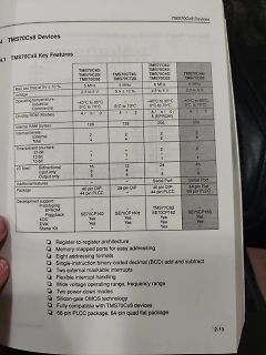
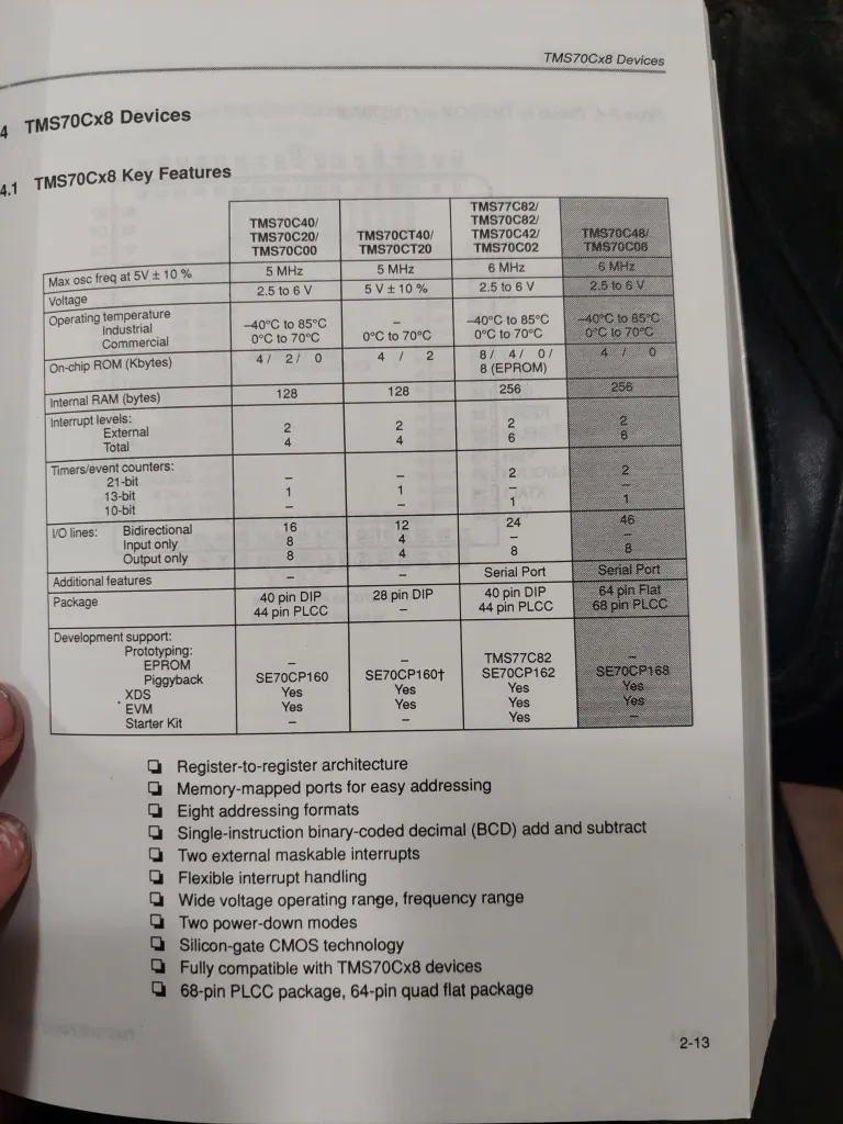
TMS70Cx8 Devices
4.1 TMS70Cx8 Key Features
TMS70C40/TMS70C20/TMS70C00
Max osc freq at 5V ± 10%
5 MHz
Voltage
2.5 to 6 V
Operating temperature
Industrial
Commercial
-40°C to 85°C
0°C to 70°C
TMS70CT40/TMS70CT20
5 MHz
5V ± 10%
128
Internal RAM (bytes)
128
256
256
TMS70C82/TMS70C82/TMS70C42/TMS70C02
6 MHz
2.5 to 6 V
-40°C to 85°C
0°C to 70°C
TMS70C48/TMS70C08
6 MHz
2.5 to 6 V
-40°C to 85°C
0°C to 70°C
Interrupt levels:
External
Total
2
6
2
6
2
6
2
6
I/O lines
Unterschied. Die Spitze hält allerdings ein Cortex-M3 (lpc1343) mit 26KB. Renesas RX liegt bei 28KB. Der Flop ist ein PIC32 mit 41KB - der einzige, der schlechter als die at(x)megas abschneidet. Das liegt wohl daran, dass ich den "freien" mips32-elf-gcc" verwende, also keinen Compiler von Microchip
bekommt mit dem PicKit3 für ca. 70.- Euro einen guten Debugger und von Microchip einen kostenlosen C-Compiler. Der PIC24 hat übrigens mit dem 8Bit-PIC nichts am Hut, also wer den 8Bit-PIC nicht mag (so wie ich), kann sich trotzdem mit dem 16Bit-PIC anfreunden. Gibt's übrigens bei Reichelt im DIL28-Gehäuse
battery detector 18.5 mA receive Temperature sensor and 8-bit 30 mA @ +13 dBm transmit ADC –40 to +85 °C temperature range 85 mA @ +20 dBm transmit Integrated voltage regulators Data Rate = 0.123 to 256 kbps Frequency hopping capability FSK, GFSK, and OOK On-chip crystal tuning RFM22B/23B modulation 14-
battery detector 18.5 mA receive Temperature sensor and 8-bit 30 mA @ +13 dBm transmit ADC –40 to +85 °C temperature range 85 mA @ +20 dBm transmit Integrated voltage regulators Data Rate = 0.123 to 256 kbps Frequency hopping capability FSK, GFSK, and OOK On-chip crystal tuning RFM22B/23B modulation 14-
sdc zu sein und da gibt es ein Problem was wohl auch Clonezilla hat und weshalb W10 nix macht: [c] jv@JamesWebb:~$ blkid /dev/sda1: UUID="1ac71602-89cf-4c83-9a0a-99762e13e79c" BLOCK_SIZE="4096" TYPE="ext4" PARTUUID="7f4322d5-01" jv@JamesWebb:~$ jv@JamesWebb:~$ lsblk -f NAME FSTYPE FSVER LABEL
sudo] password for jv: mount: /media/jv: can't read superblock on /dev/sdc. jv@JamesWebb:~$ [/c]
event pending flag, set by H/W while WKT time out WKTIF 0C.3 W 0 write 0: clear this flag; write 1: no action R - INT2 (PA7 or PB5) interrupt event pending flag, set by H/W at INT2 INT2IF 0C.2 pin’s falling edge W 0 write 0: clear this flag; write 1: no action INT1 (PA1 or PB1) interrupt event pending flag, set by H/W at INT1 INT1IF 0C.1 R - pin’s falling/rising edge W 0 write 0: clear this flag; write 1: no action R - INT0 (PA3 or PB2) interrupt event pending flag, set by H/W at INT0 INT0IF 0C.0 pin’s falling/rising
whatever their design requires. Sample demo code written in PICBasicPro and aslo Proton+ is available at the COMPSys Workbench website in the support section. It will work with most T6963C based FS D6 D4 D2 D0 nc CE WR 5v Gnd LCDs that have a2x10 header as shown on the right Pin 1 (as seen from the backside of the LCD) nc D7 D5 D3 D1 Rst CD RD Vlcd Gnd PARTS LIST C1,C3 10uf radial cap IC1 PIC mcu 28 pin C2 1uf or .1uf radial cap IC2 RS232 IC C4 100uf radial cap IC3 I2C Eeprom C5-C9 1uf smd cap IC4 Max637 R1,R3,R4 4.7k smd res LM7805 regulator R2 330 smd res X1
CAN1 reset Set and cleared by software. 0: No effect 1: Reset CAN1 Bits 24:23 Reserved, must be kept at reset value. Bit 22 I2C2RST: I2C 2 reset Set and cleared by software. 0: No effect 1: Reset I2C 2 Bit 21 I2C1RST: I2C1 reset Set and cleared by software. 0: No effect 1: Reset I2C 1 Bit 20 UART5RST:
function for the composite CIC filter, referenced to frequency response is obtained by evaluating Eq. (3) at the high sampling rate, is (1 − z−RM )N j2πf (4) H(z) = H Iz)H C = −1 N z = e R (1 − z ) RM −−k N (3) = [▯ z ] where f is the frequency relative to the low sampling rate k = fs/ R. As part of the filter
S I I I I ( C / ( / T T / / / / ( / T T / / / / / A 2 ( ( C D D D A ( ( C D D D N C C ( ( X T C ( ( X T C R ( ( ( ( ( ( X ( ( Table 1. Changed Pins Pin ATmega128 AT90CAN128 Comments for AT90CAN128 1 PEN (n.c.) Not
autom. upgedated als ich auch hier nochmals Blink getestet habe. Alles ok. Preis : 30€ 3. TL866cS. Kaum gebraucht. Neuwertiger Zustand. 89S52 und 28C256 getestet. Alles ok. Software Windows gibts im Netz. Kann ich auch als Zip zusenden. Minipro als Open Source hatte ich auch mal unter Mac OSX
Privatverkauf ohne Sachmängelhaftung. Falls das Mailsystem nicht gehen sollte hier : peter. S i e g1 (at) g mx . De Die beiden Intel Arduino sind auch neuwertig. Daten über google. Kann ggf. Zum Galileo noch eine 4GB sd Karte abgeben mit einer passenden Linux Version. Versand sind 5€ in DE. Bei
of the LCD driven and the N-lines. NW[7:0]: Specify the number of lines that will alternate at the N-line inversion setting (B/C = 1). N-line is equal to NW[7:0]+1. Figure 9-2: Line Inversion AC Driver N Frame N+1 Frame Back porch Front porch Back porch Front porch 1 2 3 242 255 256 1 2 3 242
verwenden oder einen keramischen Schwinger, der hätte > die Kapazitäten schon eingebaut. Zwischen -20°C und +40°C ist die Abweichung gerade mal 2% => kein Problem. Die Spannung ist konstant. D.h. einmal Abgleichen müsste reichen.
Und Alle halten sich .........Bedeckt ! Bus-System mit I2C....... Nur wo ansetzen ?
the bootstrap loader, please refer to section 9.3. The C167CS has a 256kb FLASH ROM, divided into 32kb blocks which are located at 0x00000-0x07FFF and 0x18000-0x4FFFFs. The FLASH memory can be written to up to 1000 times, enough for a considerable number of
zu diesem Thema. Lies DIch da durch. Du musst wissen, dass zuerst der ARM startet und der dann den C67xx dann loslaufen lässt. fchk
kompilieren ist etc. als WIKI im Web, erste infos: http://processors.wiki.ti.com/index.php/Category:C6-Integra ) du must natürlich kein Linux nehmen... Stefan
befinden sich in Stangen oder Reel. Hier die Liste (Datenblätter gibs beim G): *24LC01B* 256 Byte I2C EEPROM SOIC 8, 300 Stück, Preis je Stück: 3 Cent *24LC32* (ST24LC32A-I/SN) 4 KByte I2C EEPROM SOIC 8, 10 Stück, Preis je Stück: 15 Cent *LM 2575-5* Step-Down Wandler 1A / Vout 5V
. Große Mengen / Bauteile werden teurer. Anfragen bitte per Mail und nicht ins Forum: bauteile ät lostemp punkt de
den funktionierenden Code? http://www.mikrocontroller.net/articles/Entprellung#Komfortroutine_.28C_f.C3.BCr_AVR.29 > Übrigens, da ich viel mit Tinys (wenig Pins) mache, diese > Tastenentprellung funktioniert auch für Eingänge, die gleichzeitig auch > als Ausgang genutzt werden. Das macht
Ich lasse den ATmega 2560 auf dem Arduino-Board mit seinen voll möglichen 16MHz takten. Der T/C0 wird ja durch 1024 heruntergeteilt, was 15625 Hz bedeutet und ein Timertakt somit 64µs dauert. Ein T/C0 Überlauf würde somit bei 256 * 64µs = 16384µs oder 16,384ms erfolgen. Jetzt müsste ich ja
been the case. working draft AT Attachment-3 (ATA-3) Page 159 X3T10/2008D Revision 6 5v 0v 50ns/div horizontal 1v/div vertical Figure C.7 – Oscilloscope trace at device end of DIOR- signal on a typical system C.2.2 What are the options
int c) { unsigned int w = c; at91_set_gpio_value(CmdPin, 1); ndelay(5); spi_write(spi, (u8 *)&w, 2); at91_set_gpio_value(CmdPin, 0); ndelay(5); } static void spi_data(struct spi_device *spi, unsigned int d
a comb filter [ H (z)=(1-z -RM )] referenced to the high sampling rate. The comb section operates at a C lower sampling rate ( f SR) than the integrator section. fS= input high sampling rate. R = sampling rate reduction factor. M is a differential delay typically one or two. This is shown below. Note
Analogeingang einlesen. Es kommt das Programm und der Anschluss hier aus dem Forum unter AVR-GCC-Tutorial#ADC_.28Analog_Digital_Converter.29 zum Einsatz. Das LCD ist jetzt am PortB angeschlossen. Zwischen Vcc und Gnd liegt ein Poti als Spannungsteiler. Der Mittelabgriff liegt am Analogeingang 1 (PortC0) Download
ist der Helligkeitsanstieg an der LED nicht linear. Durch den Timer Vor-Teiler von 256 (TCCR0B =(1 fOCnxPWM= 1.000.000Hz/(256*256)=15,26Hz Download Software: Programm als ZIP Aufgaben: Hex-File in Controller laden. Eine Simulation der PWM ist mit meinem AVR Studio nicht gelungen siehe
C-Compiler, weil das OS in C geschrieben war. DEC selbst war mehr Pascal lastig. Es gibt ja da auch so eine Embedded VAX Geschichte (Vaxeln) die auch stark Pascal lastig ist. Es gab ne KA630 mit ausgeschaltetem
Pille schrieb im Beitrag #6893190: > sondern ein native C-Compiler von der PDP-11. Ja eben. Steve Johnsons "Portable C Compiler".
Smartphones Security Systemsunctional Diagrams Block Diagram V CC 16-BIT SDA ADC SCL VISIBLE +IR I C PHOTODIODE AO 6-BIT RANGE DIGITAL CDR, TIM PROCESSING INT MAX44009 CONTROL 16-BIT ADC N PHOTODIODE Pin Configurations appear at end of data sheet. Functional Diagrams continued at end of data sheet.
the 50 mV/Div and 0.5 V/Div settings; their advantage is a reduced noise level. Change DSO2100.EXE at hex file offset 29782 from hex 20 to hex 03 and at hex file offset 297c6 from hex 10 to hex 03 to see this. DSO2100.EXE seems to keep the trigger level fixed at 50% (hex 7f); the PCB is apparently not
-lead TQFP, 64-lead QFN, 64-lead CA-BGA Op– 2.7 - 5.5Vages Operating temperature – Industrial (-40°C +85°C) and Automotive (-40°C +125°C) Maximum Frequency – 8 MHz at 2.7V - Industrial range Rev. 4251A–AVR–May 2003 16 MHz at 4.5V - Industrial range Advance Information 1 Advance Information Disclaimer
-lead TQFP, 64-lead QFN, 64-lead CA-BGA Op– 2.7 - 5.5Vages Operating temperature – Industrial (-40°C +85°C) and Automotive (-40°C +125°C) Maximum Frequency – 8 MHz at 2.7V - Industrial range Rev. 4251A–AVR–May 2003 16 MHz at 4.5V - Industrial range Advance Information 1 Advance Information Disclaimer
staatlichen Rechner diese veralte CPU wegen Leistungsschwächen nicht haben wollen: "The Elbrus-8C server is very weak compared to Intel Xeon 'Cascade Lake'," said Anton Zhbankov, a representative for SberTech, said at the Elbrus Partner Day conference (via ServerNews.ru) earlier this month. "Insufficient memory [256MB], slow memory, few cores, low frequency. Functional requirements not been met at all." Und die nachgewiesenen Mängel beschränken sich nur auf die CPU. Selbst am Rack fühlen sich die Kunden verarscht
2013–2016, Texas Instruments Incorporated Product Folder Links: ADS1220 ADS1220 www.ti.com SBAS501C –MAY 2013–REVISED AUGUST 2016 6.5 Electrical Characteristics Minimum and maximum specifications apply from T = –40°C toA+125°C. Typical specifications are at T = 25°C. A All specifications are at AVDD

 Bild
Bild