-
Bild
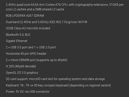
Technische Spezifikationen eines Mikrocontrollers oder Einplatinencomputers
2.4GHz quad-core 64-bit Arm Cortex-A76 CPU, with cryptography extensions, 512KB per-core L2 caches and a 2MB shared L3 cache 8GB LPDDR4X-4267 SDRAM Dual-band (2.4GHz and 5.0GHz) IEEE 802.11b/g/n/ac Wi-Fi® 32GB Class A2 microSD included Bluetooth 5.0, BLE Gigabit Ethernet 2 × USB 3.0
in „Raspberry Pi 500, ST-Entwicklerkongress und vieles andere mehr“ · Mikrocontroller und Digitale Elektronik · · Screenshots
-
Bild
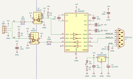
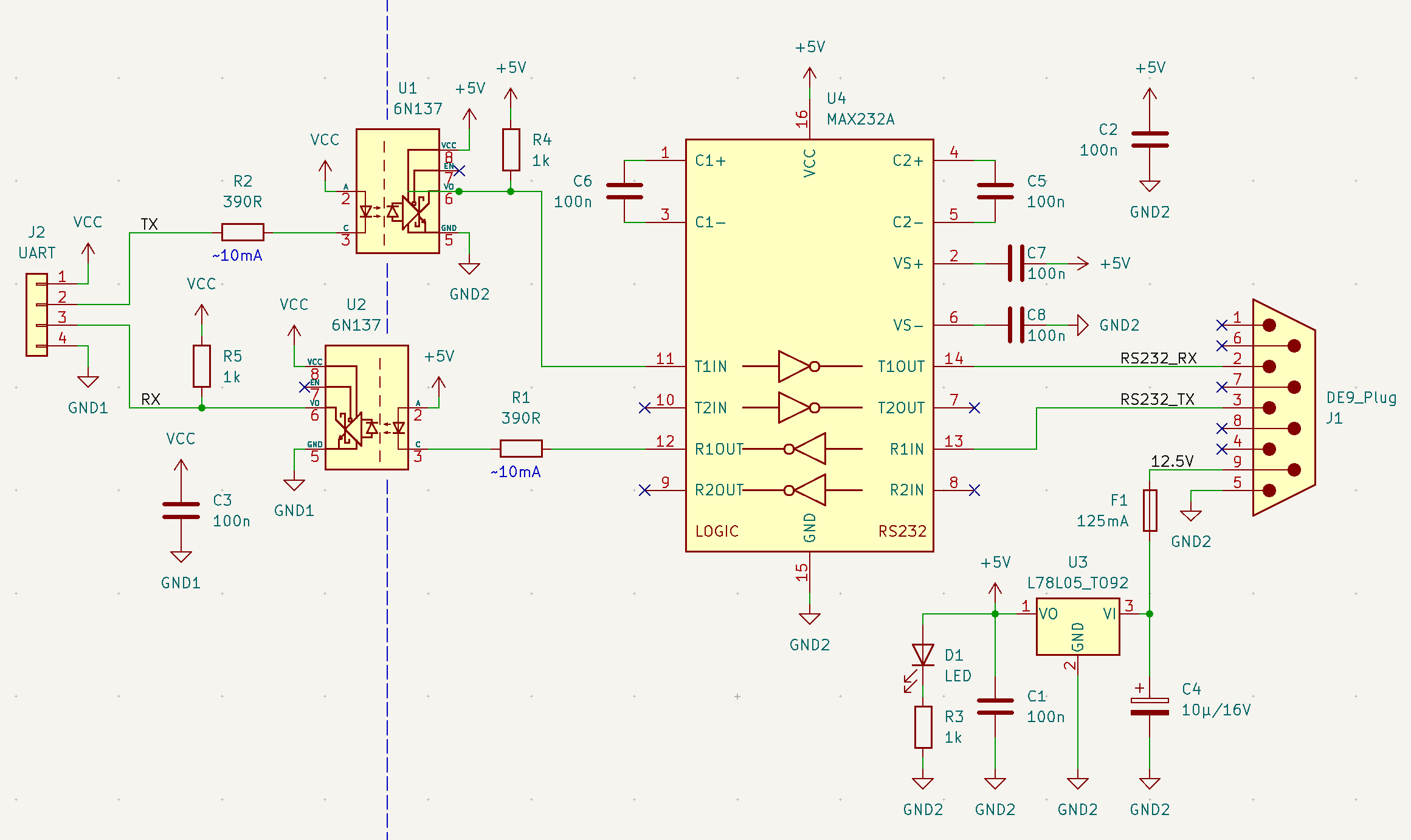
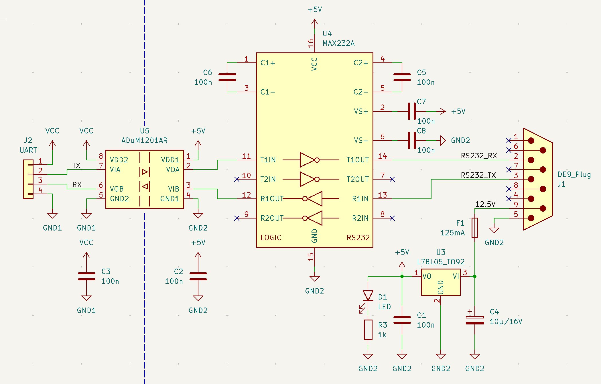
Schaltplan einer RS232-Schnittstelle mit Optokopplern und MAX232
C2-, C5 100n, VS+, VS-, C7 +5V, C8 100n, GND2, DE9_Plug J1, RS232_RX, RS232_TX, 12.5V, F1 125mA, U3 L78L05-T092, VO, GND, C4 10u/16V, D1 LED, R3 1k, GND1, C3 100n, R5 1k, U2 6N137, R2 390R, J2 UART, VCC, TX, RX, GND1, R1 390R, T1IN, T1OUT, T2IN, T2OUT, R1IN, R2IN, R2OUT, R1OUT, LOGIC, RS232
in „RS232 Isolator, 6N137 oder ADuM1201“ · Mikrocontroller und Digitale Elektronik · · Schaltpläne
-
Bild
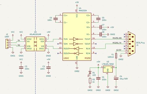
Schaltplan einer RS232-Schnittstelle mit Pegelwandler
, J1 DE9_Plug, RS232_TX, T2IN, T1IN, T1OUT, T2OUT, R1IN, R2IN, R1OUT, R2OUT, LOGIC, GND, RS232, U3 L78L05_T092, F1 125mA, +5V, VO, GND, C4 10µ/16V, C1 100n, D1 LED, R3 1k, GND2, C3 100n, C2 100n, GND1, GND2, VCC
in „RS232 Isolator, 6N137 oder ADuM1201“ · Mikrocontroller und Digitale Elektronik · · Schaltpläne
-
Datei
lcd.c
0x02, // f 0x00, 0x18, 0xA4, 0xA4, 0xA4, 0x7C, // g 0x00, 0x7F, 0x08, 0x04, 0x04, 0x78, // h 0x00, 0x00, 0x44, 0x7D, 0x40, 0x00, // i 0x00, 0x40, 0x80, 0x84, 0x7D, 0x00, // j 0x00, 0x7F, 0x10, 0x28, 0x44, 0x00, // k 0x00, 0x00, 0x41, 0x7F, 0x40, 0x00, // l 0x00, 0x7C, 0x04, 0x18, 0x04, 0x78, // m 0x00, 0x7C, 0x08, 0x04, 0x04, 0x78, // n 0x00, 0x38, 0x44, 0x44, 0x44, 0x38, // o 0x00, 0xFC, 0x24, 0x24, 0x24, 0x18, // p 0x00, 0x18, 0x24, 0x24, 0x18, 0xFC, // q 0x00, 0x7C, 0x08, 0x04, 0x04,
in „RS485 von ms - immer noch Einschaltprobleme“ · Mikrocontroller und Digitale Elektronik ·
-
Datei
lcd_ssd1306_gfx.c
0x02, // f 0x00, 0x18, 0xA4, 0xA4, 0xA4, 0x7C, // g 0x00, 0x7F, 0x08, 0x04, 0x04, 0x78, // h 0x00, 0x00, 0x44, 0x7D, 0x40, 0x00, // i 0x00, 0x40, 0x80, 0x84, 0x7D, 0x00, // j 0x00, 0x7F, 0x10, 0x28, 0x44, 0x00, // k 0x00, 0x00, 0x41, 0x7F, 0x40, 0x00, // l 0x00, 0x7C, 0x04, 0x18, 0x04, 0x78, // m 0x00, 0x7C, 0x08, 0x04, 0x04, 0x78, // n 0x00, 0x38, 0x44, 0x44, 0x44, 0x38, // o 0x00, 0xFC, 0x24, 0x24, 0x24, 0x18, // p 0x00, 0x18, 0x24, 0x24, 0x18, 0xFC, // q 0x00, 0x7C, 0x08, 0x04, 0x04,
in „SSD1306/1309 Library zum Darstellen von Text auf OLED Displays“ · Projekte & Code ·
-
PDF
Wii-nunchuck-datasheet.pdf
▯ @▯=@)▯ D@ D=@JOII▯M D= ▯DE▯J▯O=EI▯ O▯D@ ▯DJ▯ ?)0@JDA! ▯▯+ ) ▯ HO=M▯▯IM 2E =ICCEA JB K=?D=H5 LM5F=L? BLK?:7 +BB=D:?J=D:? K=0EB▯7 H5 LM5F=L?J▯? B K .ECKHA 9 ?EEDJKB= K: HA7+0A =+B0H+I EB@+H7M0E+B 2 ZX-NUNCHUK documentation !8/8, 1/ IC1 6+ !8/8, ▯. ▯% 78L33 5+, ▯8▯▯ ▯8▯▯ ,/7 )▯ $8.P $8.P ▯▯P +#8 .!"
in „AVR8ASM TWI Interrupt“ · Mikrocontroller und Digitale Elektronik ·
-
PDF
grundig32zollLedTV.pdf
r E 8 n e n V e r w c h t g r i s d e W l s HI v p s lr 2 t 2 n u . p t E a n a e r s r r n e c r w e e a T e l S L OB e d t i 0 r 0 a f 0 e o f l a o t n f v t e r l h h i e i E i i TNENOPMOC/ SHV- S/ VT A N 78 p 8 m 7 8 b p o 7 m l c i o e
in „Reparaturbericht LED-TV Grundig 32 VLE 5620 BN Ton gut, aber kein Bild“ · Analoge Elektronik und Schaltungstechnik ·
-
PDF
Handbuch_SE4942_Eprom_Programmer_pdfa-2b_150dpi.pdf
MDS86, Transfer direction SE4942 External equipment —Check sum—=> 1123 4.5h8c78 9u101112131145 ;]o 2]0700 o]o'2] usa check sum 0,0] Addre|sRecotypeCheckum ® ® ® 12 „ Lg yte count 1 Start mark L_—_Complement öf Lö mark End Extended address code AS record sum— 11— N-3-210-1 count
-
Bild
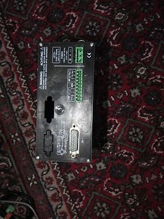
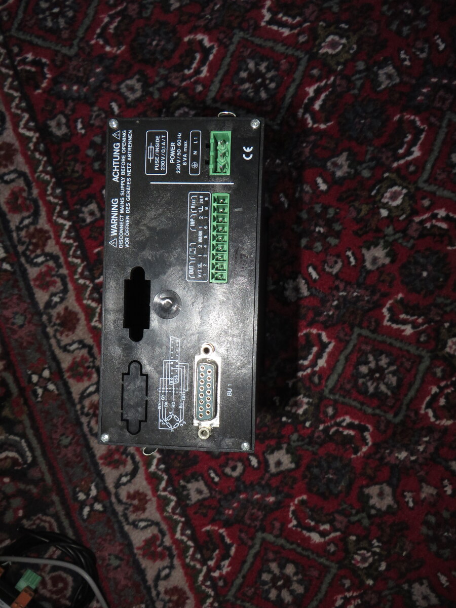
Rückseite eines Netzteils mit Anschlussklemmen
SUPPLY BEFORE OPENING VOR OFFENEN DES NETZ ABTRENNEN FUSE / INPUT 315A / 1A POWER 230V / 50, 60 Hz VA N L1 CE L N 1 2 3 4 5 6 7 8 9 10 11 12 13 14 15 16 17 18 19 20 21 22 23 24 25 26 27 28 29 30 31 32 33 34 35 36 37 38 39 40 41 42 43 44 45 46 47 48 49 50 51 52 53 54 55 56 57 58 59 60 61 62 63 64 65 66 67 68 69 70 71 72 73 74 75 76 77 78 79 80 81 82 83 84 85 86 87 88 89 90 91 92 93 94 95 96 97 98 99 100 101 102 103 104 105 106 107 108 109 110 111 112 113 114 115 116 117 118 119 120
in „[V] 2 Stück Anzeiger MVD 2510“ · Markt · · Fotos
-
Bild
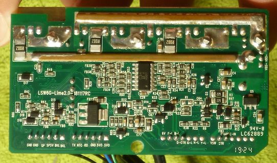
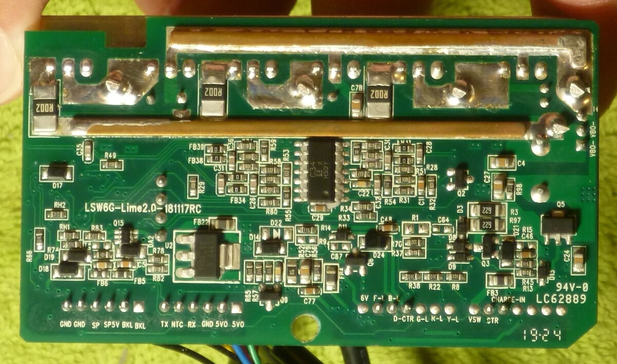
Foto einer bestückten Leiterplatte
Z008, C78, Z008, Z008, FB39, R55, C36, C28, V80-, V80-, R49, FB38, C31, R58, C3, R28, C27, C4, D17, R96, RH2, LSW6G-Lime2.0-181117RC, Q2, RH1, R83, Q15, FB34, R80, R55, R3, 229, R97, D22, C29, R33, C31, R1, C64
in „BLDC Controller mit STM32F103C8T6 Geschwindigkeitsbegrenzer in der .hex“ · Mikrocontroller und Digitale Elektronik · · Platinenfotos
-
PDF
AntenneDCF77_V2.pdf
Antenne_V2 Kondensator Kapazität: 4,74 nF (gemessen bei 77.5kHz) Spule a [mm]* L [µH]** Q [1] fres [kHz] 0 569 15 96,91 2 625 25 92,47 4 691 27 87,94 6 743 28 84,81 8 794 29 82,04 10 831 30 80,19 12 860 30 78,83 14 881 30 77,88 16 897 31 77,19 18 903 29 76,93 * Abstand der Spule
in „Induktivitätswert für eine 77,5kHz Ferritantenne“ · HF, Funk und Felder ·
-
PDF
an19fc.pdf
⎟ (39) L2 independent of the actual capacitance of C4. ⎝ VIN ⎠ ( )R2 E( ) V ( IN− V OUT ( )OUT with V P-P = 25mV, L1 = 200μH, f = 40kHz, V = 20IN L2≈ VOUT = 5.2V; V 2π f 2 L1 V (41) ( P-P ( ) ()( ) ( IN ⎛ −6⎞
in „LT1270 dimensionieren“ · Analoge Elektronik und Schaltungstechnik ·
-
PDF
Elektor83.PDF
2,65 4018 1,70 4549. 11,50 PD22 LS11 , -,65 15241. 2,65 401I -,85 4551. . 2,80 BAMS PD24 LS12. -,75 L5242. 2,65 4020 1,40 4553. . 7,90 M2101........6.95 PD28 LSl3 . -,75 1S243. 2,65 4021 1,75 A EEA . 4 r - M 21L02.......,75 PD4C LS14. 1,20 L5244. 2,65 4022 1,40 4555. .1,50 M2102........2,75 LS15. -,65
in „Das Ende des Z80“ · Mikrocontroller und Digitale Elektronik ·
-
Datei
ssd1329.c
/ f { 0x0c, 0x52, 0x52, 0x52, 0x3e }, // g { 0x7f, 0x08, 0x04, 0x04, 0x78 }, // h { 0x00, 0x44, 0x7d, 0x40, 0x00 }, // i { 0x20, 0x40, 0x44, 0x3d, 0x00 }, // j { 0x7f, 0x10, 0x28, 0x44, 0x00 }, // k { 0x00, 0x41, 0x7f, 0x40, 0x00 }, // l { 0x7c, 0x04, 0x18, 0x04, 0x78 }, // m { 0x7c, 0x08, 0x04, 0x04, 0x78 }, // n { 0x38, 0x44, 0x44, 0x44, 0x38 }, // o { 0x7c, 0x14, 0x14, 0x14, 0x08 }, // p { 0x08, 0x14, 0x14, 0x18, 0x7c }, // q { 0x7c, 0x08, 0x04, 0x04, 0x08 }, // r { 0x48, 0x54, 0x54, 0x54, 0x20 }, /
in „SPI-Problem mit AVR“ · Mikrocontroller und Digitale Elektronik ·
-
PDF
Sheet1_AmpV2.pdf
PIR640PIR6401 PIR6502PIR6501 17 GND GND 2.2K 2.2K +12V R2929 10µF PI1.5R2PIR2901 C2 PIC190 GND 10µF8 100nF L11L C0 PIC1902 PICC2121 PICC22 P I L 1 1 0P I L 1 1 0 1 PIR302 PIR6601PIR6602 PIC210nF PIC200nF 7µH R3R33 10K PIC520 PICOC40 3.3R COJ11 CC7 8 VREG C2020ND GND GND GND C5252 PI1nF1 PIC402 J11 PIC78PIC7802
in „Verstärker TAS5630“ · Analoge Elektronik und Schaltungstechnik ·
-
Datei
asmjbt3.a51
37 -- '7' DB 0x20 ;20 -- ' ' DB 0xB3 ;B3 -- '' DB 0x2A ;2A -- '*' DB 0x05 ;05 -- '' DB 0x4C ;4C -- 'L' DB 0xE5 ;E5 -- '' DB 0x4C ;4C -- 'L' DB 0xB4 ;B4 -- '' DB 0x0A ;0A -- '' DB 0x00 ;00 -- '' DB 0x40 ;40 -- '@' DB 0x21 ;21 -- '!' DB 0x75 ;75 -- 'u' DB 0x4C ;4C -- 'L' DB 0x00 ;00 -- '' DB 0x20 ;20 -
in „Eprom von Denon DJ Laufwerk defekt Winbond 78e52“ · Mikrocontroller und Digitale Elektronik ·
-
PDF
ds.pdf
0.370 D1 8.01 8.23 0.315 0.324 E 10.04 10.28 0.395 0.405 E1 7.88 8.08 0.310 0.318 e 2.54 BSC 0.100 BSC L 14.73 15.75 0.580 0.620 L1 2.29 2.79 0.090 0.110 L2 1.15 1.39 0.045 0.055 L3 1.27 1.77 0.050 0.070 6 HMG15N60D/HMG15N60/HMG15N60F TO-220-3L-C Package Information Dimensions In Millimeters Dimensions
in „Datenblatt Cypress cca7001“ · Mikrocontroller und Digitale Elektronik ·
-
Datei
LCD_320x240_Vers3_neu.asm
dann weiter LCD_out: ldi tempi, XSize mov X_Cnt, tempi in tempi, PORTB cbr tempi, 1<<CLOCK mov clockL, tempi sbr tempi, 1<<CLOCK mov clockH, tempi hloop: ;Loop für 1 Zeile out PORTB, clockL ;PCLK L ld tempi, Y+ nop out PORTB, clockH ;PCLK H out PORTC, tempi ;Low Nibble ausgeben out PORTB, clockL ;PCLK L swap tempi out PORTC, tempi ;High Nibble ausgeben out PORTB, clockH ;PCLK H dec X_Cnt brne hloop out PORTB, clockL ;PCLK L sbi PORTB, LP dec C_Cnt ;Zähler für Zeichenhöhe erniedrigen nop nop cbi PORTB
in „Einfacher Low Cost LCD Controller für 320x240 LCD im Textmodus“ · Projekte & Code ·
-
Datei
LCD_320x240_Vers4.asm
Interrupt Einsprung ldi tempi, XSize mov X_Cnt, tempi in tempi, PORTB cbr tempi, 1<<CLOCK mov clockL, tempi sbr tempi, 1<<CLOCK mov clockH, tempi hloop: ;Loop für 1 Zeile out PORTB, clockL ;PCLK L ld tempi, Y+ nop out PORTB, clockH ;PCLK H out PORTC, tempi ;Low Nibble ausgeben out PORTB, clockL ;PCLK L swap tempi out PORTC, tempi ;High Nibble ausgeben out PORTB, clockH ;PCLK H dec X_Cnt brne hloop out PORTB, clockL ;PCLK L sbi PORTB, LP dec C_Cnt ;Zähler für Zeichenhöhe erniedrigen nop nop cbi PORTB
in „Einfacher Low Cost LCD Controller für 320x240 LCD im Textmodus“ · Projekte & Code ·
-
Datei
stk500_1200.asm
stop bits). ;;; Ser_Send_Byte: 8: 7a e0 ldi r23, 0x0A ; 10 a: 40 95 com r20 c: 08 94 sec ; set carry L_Ser_Send_Next_Bit: e: 10 f4 brcc L_001 ; branch to L_001 if carry clear 10: 91 98 cbi 0x12, 1 ; clear bit 1 of portd 12: 02 c0 rjmp L_002 ; L_001: 14: 91 9a sbi 0x12, 1 ; set bit 1 of portd 16: 00 00
in „AVRISP => Hex-Datei vom 1200er“ · Mikrocontroller und Digitale Elektronik ·
-
PDF
Inverter_MAX660.pdf
vs. LOAD CURRENT vs. OSCILLATOR FREQUENCY 100 - 1.2 3 -5.0 - X ) X A V+ = 5.5V M ( M ILOAD= 1mA M L 1.0 V+ = 1.5V 92 P S ) -4.5 LOAD = 10mA ) M 0.8 V+ = 2.5V E ( F G C 84 P L E V+ = 3.5V R 0.6 V -4.0 I V+ = 1.5V V+ = 4.5V E V+ = 3.5V T F 76 A P LOAD = 80mA E L 0.4 U V O V+ = 2.5V T V+ = 4.5V -3.5 68
in „Spannungspeaks / Ripple durch Schaltregler. Abhilfe?“ · Analoge Elektronik und Schaltungstechnik ·
-
Bild
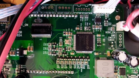
Nahaufnahme einer bestückten Leiterplatte mit Mikrocontroller
CAN_CAN, WY_DR, SW_DR, R270, Q7, R214, GND, C23, R79, DCDC_EN, GND, SWCLK, SWDIO, V3.3D, C53, C37, C45, L9, R101, C110, D21, R69, R57, R37, C38, D27, D30, R155, R156, R66, R106, R112, R153, R154, C80, R171, U22, C79, C102, C67, L7, C7, C59, R78, R20, LED2, U15, U25, U13, R144, R110, R134, C68, C65, D42,
in „ALLPOWERS S2000 PRO Reparaturhilfe“ · Mikrocontroller und Digitale Elektronik · · Platinenfotos
-
Bild
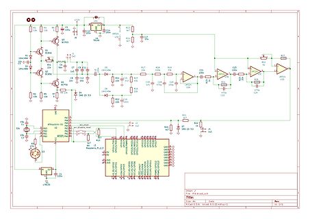
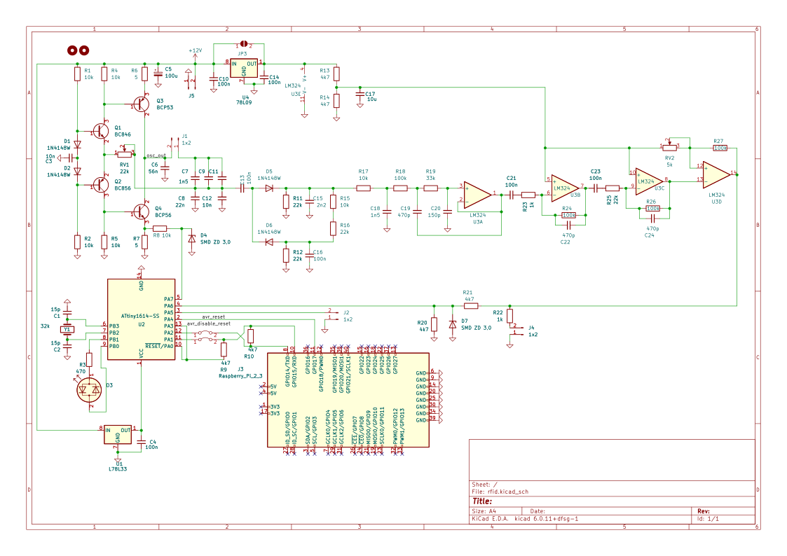
Schaltplan mit Raspberry Pi und Verstärkerschaltung
D6, U2, ATtiny164-55, P3, P4, P1, P0, RESET/PA0, Raspberry_Pi_2_3, 3v3, 5v, GPIO0 bis GPIO13, J4, L78L33, IN, OUT, GND
in „Bitte nicht nachmachen: PE des DSO abkleben?“ · Analoge Elektronik und Schaltungstechnik · · Schaltpläne
-
PDF
SDA5252-2_Siemens.pdf
30 A11 VDDA 72 29 A5 I 73 28 A9 REF CVBS 74 27 A6 P3.7 75 26 A8 P3.6 76 25 A7 P3.5 77 24 A13 P3.4 78 23 A12 P3.3 79 22 A14 P3.2 80 21 A15 1 2 3 4 5 6 7 8 9 10 11 12 13 14 15 16 17 18 1920 1 1 S D 1 1 E 3 3 1 1 1 1 1 1 1 1 VS D L A S EL 4 1 4 UEP09855 P P P P P P P P P P P V T T R A / A 8 X X 1 A A Figure
in „PAL-Röhren TV auf NTSC umbauen“ · Analoge Elektronik und Schaltungstechnik ·
-
Datei
vs1011_1.c
zeros.: init: 0x53 0xEF 0x6E n 0 0 0 0 n z.b. 126 To exit the sine test, send the sequence 0x45 0x78 0x69 0x74 0 0 0 0. Zum read test: SCI STATUS (RW) Name Bits Description SS VER 6..4 Version SS APDOWN2 3 Analog driver powerdown SS APDOWN1 2 Analog internal powerdown SS AVOL 1..0 Analog volume control
in „Sinustest des vs1011“ · Mikrocontroller und Digitale Elektronik ·
-
PDF
NPX-35TFR-product-data-sheet.pdf
1 A/C NP12-6 NP12-6FR 12.0 151 5.95 50 1.97 101 3.98 2.04 4.48 1 A/C NP0.8-12 NP0.8-12FR 0.8 96 3.78 25 0.98 61 2.42 0.37 0.82 7 H/I NP1.2-12 NP1.2-12FR 1.2 97 3.82 48 1.89 56 2.20 0.57 1.25 3 A NP2-12 NP2-12FR 2.0 150 5.91 20 0.79 89 3.50 0.70 1.54 8 B NP2-12-C NP2-12CFR 2.0 182 7.17 24 0.93 61 2.40 0.73 1.61 6 L NP2.3-12 NP2.3-12FR 2.3 178 7.01 35 1.38 67 2.64 1.02 2.15 1 A NP2.6-12 NP2.6-12FR 2.6 134 5.28 67 2.64 66 2.60 1.36 3.00 3 A NP2.9-12 NP2.9-12FR 2.9 79 3.11 56 2.20 105 4.13 1.24 2.73 1 A/C NP3-12 NP3
in „[S] Polschutzkappen für 5.5mm Anschlüsse von Akkus“ · Markt ·
-
PDF
PT1000_-_Schaltungberechnung.pdf
darf 1mA nicht übersteigen: Imess <= 1mA => R 1R >=212k Wahl: R = 12k R 2 = 910R ... 1.3k (-23°C ... 78°C) U p 12V * (R / (R2+R ))1 2 U pst die Spannung am positiven OPV-Eingang Für R =2910R gilt: Up= 0,846V Für R 2 = 1k3 gilt: Up= 1,173V 2. Forderung: R und R3sollen s4 gewählt werden, dass U >= 1,173V
in „PT1000 - konkrete Schaltung“ · Mikrocontroller und Digitale Elektronik ·
-
PDF
sn75452b.pdf
JG, and P packages. FUNCTION TABLE schematic (each driver) V (each driver) CC A B Y 4 k 1.6 k 130 L L L (on state) L H L (on state) H L L (on state) Y H H H (off state) A positive logic: B Y = AB or A+B 500 1 k GND Resistor values shown are nominal. electrical characteristics over recommended operating
in „Suche Datenblatt“ · Mikrocontroller und Digitale Elektronik ·
-
Datei
lab9a_c180.txt
$20 $0D LD9EA ldab L1000 ;$D9EA $F6 $10 $00 cmpb #'z' ;$D9ED $C1 $7A bne LD9EA ;$D9EF $26 $F9 com L0001 ;$D9F1 $71 $00 $01 clr L1000 ;$D9F4 $79 $10 $00 LD9F7 bra LD9EA ;$D9F7 $20 $F1 inc L1000 ;$D9F9 $72 $10 $00 ldab #$80
in „HCS12 CPU Disassembler“ · Mikrocontroller und Digitale Elektronik ·
-
PDF
xfft_ds260.pdf
138 149 24784 166.34 1 8k Str N 24 24 U C N N - 6 Y XC6SLX150T 5503 5355 9030 128 146 141 24785 175.78 2 ( 1 512 R2L Y 24 24 S C N N B - N XC6SLX150T 930 902 1299 6 8 188 5854 31.14 U DS260 March 1, 2011 www.xilinx.com 45 Product Specification LogiCORE IP Fast Fourier Transform v7.1 Table 9: Spartan-6
in „Implementierung der XILINX FFT-Core“ · FPGA, VHDL & Co. ·
-
PDF
rudi_____RX-V4A_TSR-400.pdf
H H M R R R H R R R H R R R H DGND X X 5 5 D T T + + H 12 14 4A 4B1 P 13 4 H 4B2 _ _ _ P J3 X R113 L A V H T S S P N 0 no_use 0 0 0 I 2 K R R R H R . CEC 1 47K 1 3 R78 S C67 DGND 1/25 no_use 105 15 J11 OE +1.2EARC J17 Max 90mA 1/25 8 1 no_use e C68 J J no_use u 2 L19 L15 no_use _ 8 no_use 0 0 e e L17
in „Test in der Schaltung STR3A400“ · Analoge Elektronik und Schaltungstechnik ·
-
Datei
20110326_log.txt
MB) SHARED_NC_SIZE = 0x01200000 ( 18 MB) FLASH FS Start = 0x04000000 ( 64 MB) (Scratch3=0x00000000) L1 Cache: Flags 0x0000 Instruction: SetsPerWay 256 NumWays 2 LineSize 0x0020 Size 0x4000 Data : SetsPerWay 128 NumWays 4 LineSize 0x0020 Size 0x4000 L2 Cache: Flags 0x0000 Instruction: SetsPerWay 0 NumWays
in „Pollin - Receiver-Mainboard mit Twin DVB-[T,C] Tuner, NXP PNX8950EH“ · Mikrocontroller und Digitale Elektronik ·
-
Bild
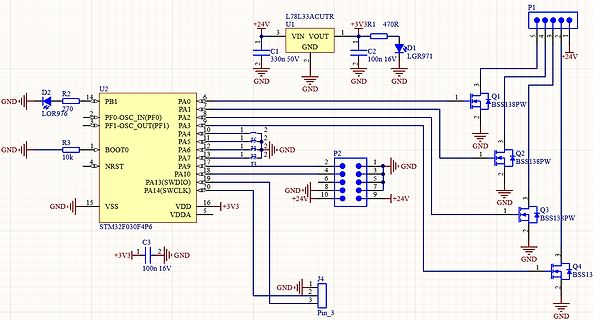
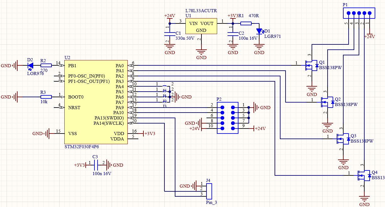
Schaltplan mit STM32F030F4P6 Mikrocontroller
+24V, U1, L78L33ACUTR, VIN, VOUT, C1, 330n 50V, GND, C2, 100n 16V, LGR971, P1, 4, 3, 2, 1, +24V, Q1, BSS138PW, 3, 2, 1, GND, Q2, BSS138PW, 3, 2, 1, GND, Q3, BSS138PW, 3, 2, 1, GND, Q4, BSS13, 3, 2, 1, GND, U2, STM32F030F4P6
in „STM32-Schaltplan so in Ordnung?“ · Mikrocontroller und Digitale Elektronik · · Schaltpläne
-
Bild
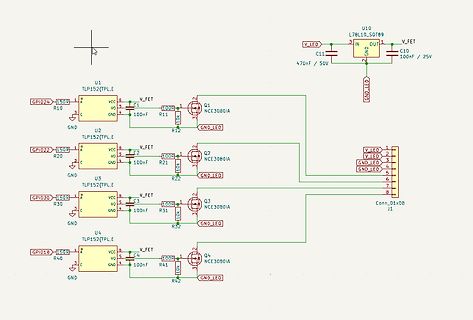
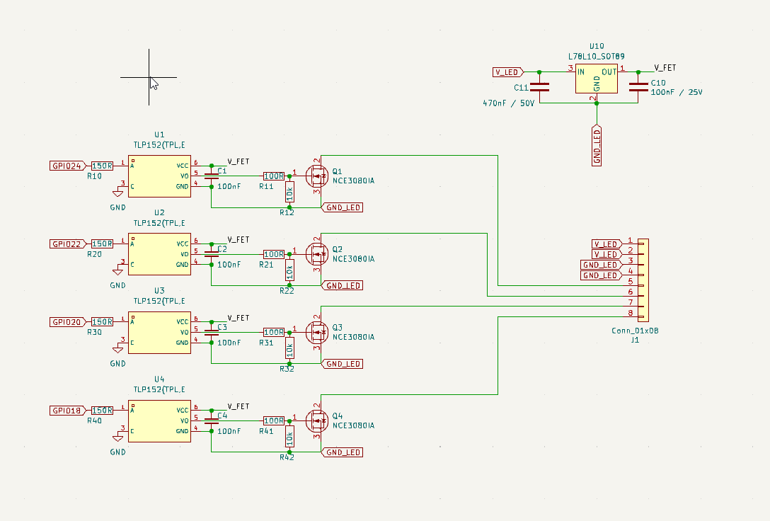
Schaltplan mit TLP152 und NCE3080A MOSFETs
U10 L78L10_SOT89 V_FET IN OUT GND V_LED C11 470nF / 50V C10 100nF U1 TLP152(TPL,E GPIO24 R10 150R V_FET VCC C1 100nF VO R11 100R GND GND_LED U2 TLP152(TPL,E GPIO22 R20 150R V_FET VCC C2 100nF VO R21 100R GND
in „Linearregler im Überstrom?!“ · Analoge Elektronik und Schaltungstechnik · · Schaltpläne
-
Bild
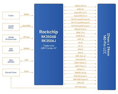
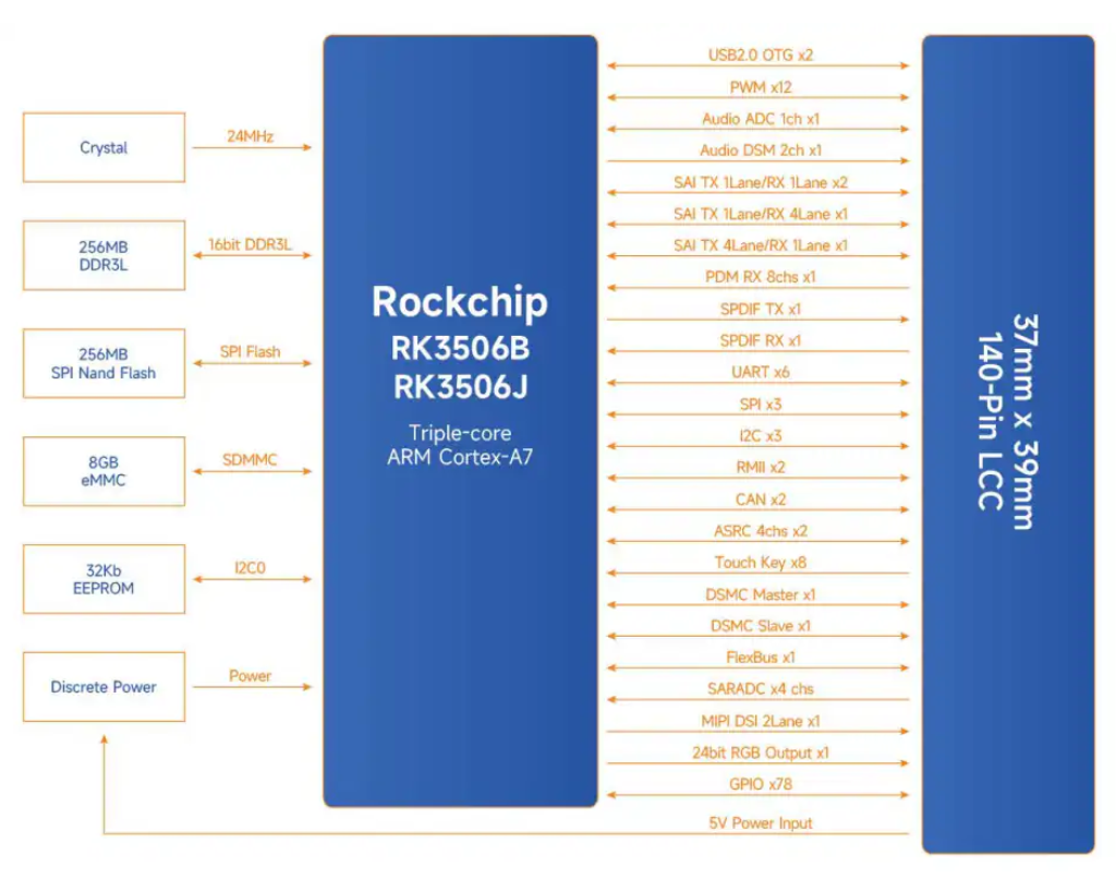
Blockschaltbild Rockchip RK3506B RK3506J
24MHz Crystal 16bit DDR3L 256MB DDR3L SPI Flash 256MB SPI Nand Flash SDMMC 8GB eMMC I2C0 32Kb EEPROM Power Discrete Power Rockchip RK3506B RK3506J Triple-core ARM Cortex-A7 USB2.0 OTG x2 PWM x12 Audio ADC 1ch x1 Audio DSM 2ch
in „Neue Bauteile: robuste SD-Karten, Stromsensoren, Widerstandsarrays uvam“ · Mikrocontroller und Digitale Elektronik · · Diagramme
-
Bild
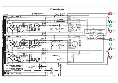
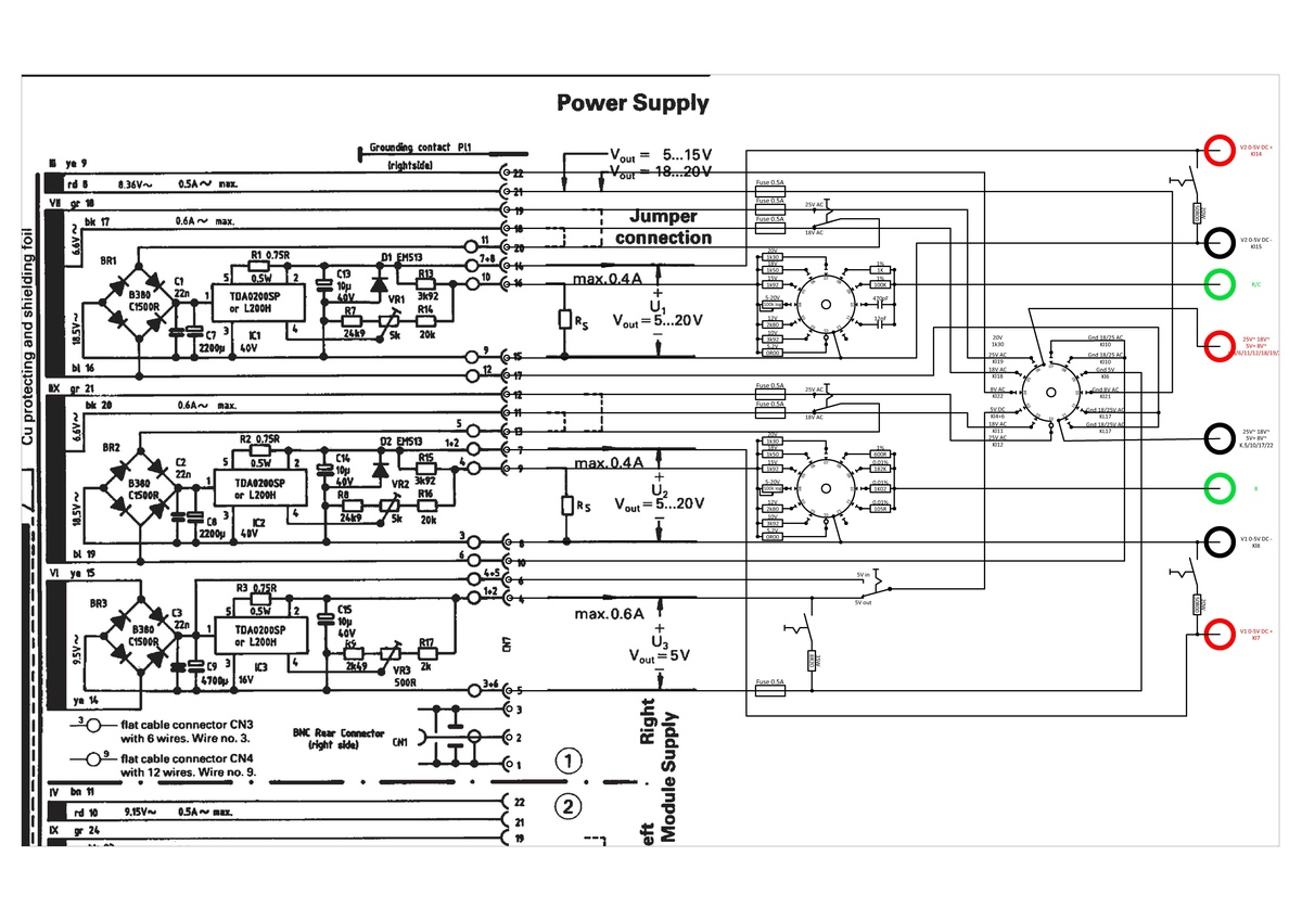
Schaltplan eines mehrstufigen Netzteils
max. 0.5A~ max. VR 17 0.6A~ max. Cu protecting and shielding foil 18.5V~ BR1 C1000 C1 TD4020SP or L200H K1 bl 16 BX gr 21 0.6A~ max. BR2 C1000 C2 TD4020SP or L200H K2 bl 19 18.5V~ 19 20 21 22 23 24 25 26 27 28 29 30 31 32 33 34 35 36 37 38 39 40 41 42 43 44 45 46 47 48 49 50 51 52 53 54 55 56 57 58 59 60 61 62 63 64 65 66 67 68 69 70 71 72 73 74 75 76 77 78 79 80 81 82 83 84 85 86 87 88 89 90 91 92 93 94 95 96 97 98 99 100 101 102 103 104 105 106 107 108 109 110 111 112 113 114 115 1
in „WOMA HAMEG HM800X-Test Unit“ · Projekte & Code · · Schaltpläne
-
PDF
27512EP_EDA.pdf
CALL L1CE1 73 jmp Z,L1939 74 SUB 030 75 mov [si-002],A 76 mov HL,01934 77 mov B,6 78 L1A02 DEC A 79 jmp Z,L1A0A 80 INC HL 81 DJNZ L1A02 82 jmp L19DA 83 ; 84 L1A0A mov L,[HL] 85 mov B,007 86 L1A0D mov A,[HL]
in „EDA-Dateien bearbeiten“ · Mikrocontroller und Digitale Elektronik ·
-
PDF
047304JES_2013.pdf
Parameters of 18650 test cell. Parameters Anode (Graphite) Separator Cathode (NCM) Thickness (μm) 81 20 78 Porosity 0.264 0.46 0.281 Loading (mAh/cm )2 4.5 — 3.9 Electrolyte concentration (mol/L) 1.2 Particle (agglomerate) radius (μm) 10 — 5 Experimental with boundary condition on particle surface: ▯ To explore
in „Lithium Ionen Batterie auf 4,2V bei 0°C aufladen sicher?“ · Analoge Elektronik und Schaltungstechnik ·
-
PDF
13_FAI_H11L2M_01.pdf
6-PIN DIP OPTOISOLATORS LOGIC OUTPUT H11L1M H11L2M H11L3M PACKAGE SCHEMATIC ANODE 1 6 V CC 6 6 CATHODE 2 5 GND 1 1 3 4 V O 6 1 DESCRIPTION The H11LXM series has a high speed integrated circuit detector optically coupled to a gallium-arsenide
in „24VDC per Optokoppler an µC“ · Mikrocontroller und Digitale Elektronik ·
-
PDF
13_FAI_H11L2M_01.pdf
6-PIN DIP OPTOISOLATORS LOGIC OUTPUT H11L1M H11L2M H11L3M PACKAGE SCHEMATIC ANODE 1 6 V CC 6 6 CATHODE 2 5 GND 1 1 3 4 V O 6 1 DESCRIPTION The H11LXM series has a high speed integrated circuit detector optically coupled to a gallium-arsenide
in „Logic-Level-MOSFET über Optokoppler???“ · Analoge Elektronik und Schaltungstechnik ·
-
PDF
EMS_PIC.pdf
1 2 3 4 5 6 7 8 V _ 5 DC1 1µ2H S + 2 +VIN +VOUT 4 E 100n 100n L3100n 3 D EMS Bus 4700µH 1 -VIN -VOUT 3 V 2 D7 C6 DC/DC CONVERTER C7 C8 U1P 1 L1 D EMS_TX 2 µ k R C1 BAT54S M C 1 IC1A 4 VA-0505S 2 S A JP1 68p 6 R1 3 n 3 1 R7 V A 4700µH T C 1 2 EMS_232_RX D8 D B 10K
in „Buderus EMS-"Gateway" mit PIC18F / Sammelbestellung“ · Haus & Smart Home ·
-
PDF
BAT54.pdf
, Molded Plastic G E · Case material - UL Flammability Rating H 0.45 0.60 Classification 94V-0 G 1.78 2.05 K · Moisture sensitivity: Level 1 per J-STD-020A M H 2.80 3.00 J L · Terminals: Solderable per MIL-STD-202, D J 0.013 0.10 Method 208 K 0.903 1.10 · Polarity: See Diagrams Below L 0.45 0.61 · Weight
in „SMD Bauteil identifizieren“ · Mikrocontroller und Digitale Elektronik ·
-
PDF
D351049D.pdf
230VAC at full load VOLTAGE RANGE 180 ~ 264VAC 254 ~ 370VDC FREQUENCY RANGE 47 ~ 63Hz EFFICIENCY(Typ.) 78% 82% 83% INPUT AC CURRENT 0.3A/230VAC INRUSH CURRENT(max.) Cold start 50A/230VAC LEAKAGE CURRENT 0.25mA/ 240VAC OVER LOAD Above 105% rated output power Protection type : Hiccup mode, recovers automatically
in „LEDS hinter Konstantstromquelle dimmen“ · Mikrocontroller und Digitale Elektronik ·
-
PDF
TypeManager_Print_Test_Sheet.pdf
62 ? 63 3 0 1 2 3 4 5 6 7 8 9 : ; < = > ? @ 64 A 65 B 66 C 67D 68 E 69 F 70 G 71H 72 I 73 J 74 K 75 L 76M 77 N 78 O 79 4 @ A B C D E F G H I J K L M N O P 80 Q 81 R 82 S 83T 84 U 85 V 86 W 87X 88 Y 89 Z 90 [ 91 \ 92] 93 ^ 94 _ 95 5 P Q R S T U V W X Y Z [ \ ] ^ _ ` 96 a 97 b 98 c 99d 100 e 101 f 102 g 103h 104 i 105 j 106 k 107 l 108 m 109 n 110 o 111 6 ` a b c d e f g h i j k l m n o p 112 q 113 r 114 s 115t 116 u 117 v 118 w 119x 120 y 121 z 122 { 123 | 124 } 125 ~ 126 127 7 p q r s t u v w x y z { | } ~ € 128 129 ‚ 130 ƒ 131
-
PDF
Dot5x7.pdf
62 ? 63 3 0 1 2 3 4 5 6 7 8 9 : ; < = > ? @ 64 A 65 B 66 C 67D 68 E 69 F 70 G 71H 72 I 73 J 74 K 75 L 76M 77 N 78 O 79 4 @ A B C D E F G H I J K L M N O P 80 Q 81 R 82 S 83T 84 U 85 V 86 W 87X 88 Y 89 Z 90 [ 91 \ 92] 93 ^ 94 _ 95 5 P Q R S T U V W X Y Z [ \ ] ^ _ ` 96 a 97 b 98 c 99d 100 e 101 f 102 g 103h 104 i 105 j 106 k 107 l 108 m 109 n 110 o 111 6 ` a b c d e f g h i j k l m n o p 112 q 113 r 114 s 115t 116 u 117 v 118 w 119x 120 y 121 z 122 { 123 | 124 } 125 ~ 126 127 7 p q r s t u v w x y z { | } ~ € 128 129 ‚ 130 ƒ 131
in „Suche Font mit alphanumerischen 5x7/5x8 LCD Zeichen“ · PC Hard- und Software ·
-
PDF
EVK1104_revA.pdf
DP TDO 5 TMSUC3B R102 0R VCC3 VCC3 40 DM _ _ _ TMS VBUS E E E VDDOUTUC3B D 1 D 1 VBUSDEBUG _ _ _ U L R R R A F M M _ _ _ I I I I O P C C C DA R S S D D D D D D D D D D D D ND V UC3B Main Clock 1.8V external E E G G G V V V V V V V V V A V A L L AT32UC3B1256-AUT XC4 loop e D11 e D12 1 9 7 4 6 8 7 6 1 6 8 2 3 5 4 Q12.0-SMU4-30-30/30- r 2 r 2 1 3 2 3 4 1 1 4 1 4 1 1 1 XIN0 XOUT0 L4 - - BLM18HE152SN1 w w C88 C89 l R103 l R104 B VDDCOREUC3B Y 330R Y 330R B B B B C 22p 22p C 3 C C U B U U U U E 3 VDDPLLUC3B LED1UC3B LED2UC3B I I U L O U D D O P C C V V D D D C V V V V B A B UC3B
in „Problem mit SD Karte an AT32UC3A3256“ · Mikrocontroller und Digitale Elektronik ·
-
PDF
TriBoardManual-TC179X-V40.pdf
6 7 1 A A 1 A A A A 2 1 B B 3 2 1 B B 3 2 1 0 B 7 6 5 4 B 0 A 0 0 1 1 0 o T T T T U U U U U U U U L Y D T K Y D A N N P P N N N P P T T T T Y T T T T D L Y O T C 2 _ U U U U O O O O O O O O C D L A L D L T / / S L / / / S C U U U U D U U U U L C D L A T o c i / / / / 2 3 4 5 6 7 8 9 T/ E A T R E A
in „Schaltplan vom Starter Kit TC1797“ · Mikrocontroller und Digitale Elektronik ·
-
PDF
BettyHHU.pdf
AMB_A11 ; DQ9 32 R94 2M AMB_D7 ICT12 RST 0 AMB_A12 6 S DQ10 34 6 A10 H AMB_D10 ICT11 12 D7 1 5 A11 1 7 L 6 S DQ10 34 AMB_D6 13 5 6 3 ; 3 DQ11 36 AMB_D11 AMB_A12 5 A11 1 7 L ICT10 D6 R21 R20 R19 AMB_A13 4 A12 ; D D 3 ; 3 DQ11 36 AMB_D11 AMB_D5 14 D5 1MR 1MR 1MR C N D DQ12 39 AMB_D12 AMB_A13 4 A12 ; D D AMB_D4
in „Innenleben von Betty TV“ · Mikrocontroller und Digitale Elektronik ·
-
PDF
Lin-Transciever-Schaltung.pdf
5 4 3 2 1 VCC 12V C8 C7 U3 SMD 78L 05 22pF VCC Nur für Masternode VCC 12V 22pF 1 VIN VOUT 3 notwendig Relais-Schaltung GND D1 LL4148 C4 + GND 100nF 2 D Q1 Quarz C1 R5 D2 D 22µF/50V 560 LL4148 NO 4 1 GND e 1 i 1 A J4 2 COM F GND D6 LED
-
Datei
644.txt
I/O ports ; and cannot be used with IN/OUT instructions .equ UDR0 = 0xc6 ; MEMORY MAPPED .equ UBRR0L = 0xc4 ; MEMORY MAPPED .equ UBRR0H = 0xc5 ; MEMORY MAPPED .equ UCSR0C = 0xc2 ; MEMORY MAPPED .equ UCSR0B = 0xc1 ; MEMORY MAPPED .equ UCSR0A = 0xc0 ; MEMORY MAPPED .equ TWAMR = 0xbd ; MEMORY MAPPED .equ