-
Datei
frq16f628.asm
BIN4+2 (MSB) bis BIN4 (LSB) ; virtuell steht davor BIN+3=0 ; das mach dann 32Bit ; ; für Autorange: 1MHz Resolution bei PT=256:1 ; 256 us x 1 MHz / 256 = 1 ; 256 us = 640 Takte = 32 x 20 Takte , 00,20h=32d ; ; ; für die Messung 500 ms ; 10MHz ; 500 ms = 1250000 Takte = 62500 x 20 Takte, 0,f4,24h=62500d
in „Von 10Mhz nach 20Mhz umschreiben“ · Mikrocontroller und Digitale Elektronik ·
-
Datei
frq.asm
BIN4+2 (MSB) bis BIN4 (LSB) ; virtuell steht davor BIN+3=0 ; das mach dann 32Bit ; ; für Autorange: 1MHz Resolution bei PT=256:1 ; 256 us x 1 MHz / 256 = 1 ; 256 us = 640 Takte = 32 x 20 Takte , 00,20h=32d ; ; ; für die Messung 500 ms ; 10MHz ; 500 ms = 1250000 Takte = 62500 x 20 Takte, 0,f4,24h=62500d
in „Von 10Mhz nach 20Mhz umschreiben“ · Mikrocontroller und Digitale Elektronik ·
-
PDF
A-Universal-Small-Signal-Class-A-Buffer-V1.0.pdf
buffer designs, and still achieves outstanding performance. The op‐amp drives an emitter follower, Q1, which is loaded by an ~100mA constant current source (57mA in the low power version) formed by Q2, D1, D2 and R12. Q3 and R6 form a 5mA load for the driving op‐amp U1, which forces it to operate in
in „100W Class A, per OPV gegengekoppelt“ · Analoge Elektronik und Schaltungstechnik ·
-
PDF
Drehzahlsensor.pdf
Induktiver Sensor NBB4-12GM30-E2-V1 Abmessungen M12x1 4 0 3 3 4 17 LED 6 M12x1 Bestellbezeichnung NBB4-12GM30-E2-V1 Merkmale • 4 mm bündig Technische Daten • Erhöhter Schaltabstand Allgemeine Daten Schaltelementfunktion PNP Schließer Anschluss
in „Drehzahlmessung durch Auswerten der Inrerrupteingänge“ · Mikrocontroller und Digitale Elektronik ·
-
Bild
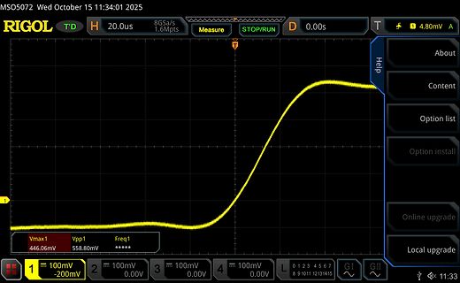
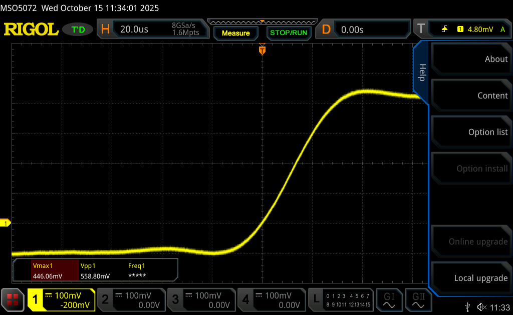
Oszilloskop-Messkurve einer ansteigenden Spannung
MSO5072 Wed October 15 11:34:01 2025 RIGOL T'D H 20.0us 8GSa/s 1.6Mpts Measure STOP/RUN D 0.00s T 4.80mV A Help About Content Option list Option install Online upgrade Local upgrade Vmax1 446.06mV Vpp1 558.80mV Freq1 ***** 100mV -200mV 100mV 0.00V 100mV 0.00V 100mV 0.00V L 0 1 2 3 4 5 6 7 8 9 10 11 12 13 14 15 GI GII 11:33
in „Mic-Signal auf Line Level mit OP-Amp?“ · Analoge Elektronik und Schaltungstechnik · · Oszi-Bilder
-
PDF
Modbus_over_serial_line_V1_02.pdf
which is not correct : the RS422 standard does not support several drivers on one balanced pair.) M aster 5 V D R P ull U p TXD 1 LT S lave P air LT TXD 0 5 V P ull D ow n P ull U p R XD 1 LT LT M aster P air R XD 0 P ull D ow n C om m on D R D R S lave 1 S lave n Figure 21: General 4-wire topology
in „Modbus RTU Terminal, Freeware Programm“ · Mikrocontroller und Digitale Elektronik ·
-
PDF
_4828319.pdf
Signal searching LED Flashing: Position Fixed Specification: General Chipset SiRF StarⅢ Frequency L1, 1575.42 MHz C/Acode 1.023 MHz chip rate Channels 20 channel all-in-view tracking Sensitivity -159 dBm Accuracy Position 10 meters, 2D RMS 5 meters, 2D RMS, WAAS enabled Velocity 0.1 m/s Time 1us synchronized
-
Bild
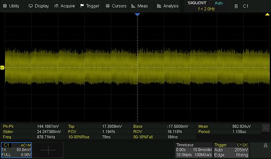
Oszilloskop Messung eines Signals
Utility Display Acquire Trigger Cursors Meas Analysis SIGLENT Auto f < 2.0Hz C1 C1 DC 205mV Pk-Pk 144.1667mV Top 17.3958mV Base -17.5000mV Mean 562.924uV Stdev 24.247360mV FOV 1.194% ROV 16.119% Period 1.138us Freq 878.71kHz 10-90%Rise 79ns 10-90%Fall 164ns C1 AC1M 50.0mV/ 0.00V
in „[V] lineares 13,8V 10A Festspannungsnetzteil“ · Markt · · Oszi-Bilder
-
Datei
AVR_Test_Board.c
retransmission disabled { (0x20|0x05), 0x17 }, //channel = 18 { (0x20|0x06), 0x3F }, //air data rate-1M,out power 0dbm,setup LNA gain-20dB { (0x20|0x07), 0x07 },// { (0x20|0x08), 0x00 },// { (0x20|0x09), 0x00 },//> { (0x20|0x0C), 0xc3 }, //LSB Addr pipe 2 { (0x20|0x0D), 0xc4 }, //LSB Addr pipe 3 { (0x20
in „Total angekotzt von AVR-Studio, ist mir noch zu helfen?“ · Mikrocontroller und Digitale Elektronik ·
-
PDF
UBN30_MODBUS.pdf
LINE 23 [mV] (Unsigned) $0018 4 $100C 2 L-L VOLTAGE LINE 31 [mV] (Unsigned) $001C 4 $100E 2 SYSTEM CURRENT [mA] (Signed, negative MSB=1) $0020 4 $1010 2 PHASE 1 CURRENT [mA] (Signed) $0024 4 $1012 2 PHASE 2 CURRENT
in „[V] Digitalzähler“ · Markt ·
-
PDF
snubber.pdf
luck! Appendix A: PSPICE Listing of AC-DC Snubber Circuit Snubber Circuit, Jim Hagerman, 11/11/94 Vin 1 0 sin(0 17.8 60 0 0) Rt 1 2 0.5 Lt 2 3 0.133mH Ct 3 0 550pF D1 3 5 _1n4007 Cload 5 0 1000uF Rload 5 0 180 ;Rs 4 0 470 ;110 ;Cs 3 4 3900pF ;0.068uF ;Cx 3 0 0.01uF ;.tran 0.01m 25m .tran 0.001m 25m 20m .probe .option ITL5 10000 * Jim Hagerman * 11/7/94 typical .model _1n4007 d + ( + n = 1.57 + is = 6.1e-10 + rs = 0.044 + tt = 7.2e-6 + cjo = 50e-12 + m = 0.25 + vj = 0.31 + eg = 1.11 + xti = 3.0 + bv = 1000 + ibv = 1e-6 + ) .end References . Rick Miller et. al.,TAA 1/
in „Motor mit Triac schalten!“ · Analoge Elektronik und Schaltungstechnik ·
-
PDF
SEPS525-Revision_0.5.pdf
M 1 i CSB M s 8 e RS P u t r RDB/E I i s WRB/RWB e n DB[17:0] a e e i m e n 2 VDDIO s g R VDD o w r D VSS l v G[127:0] ENABLE I r r e R HSYNC a B VSYNC e DOTCLK VSYNCO D OSCA1 S s D C a t OSCA2 y VDDH
in „[Sammelbestellung] 1,45" OLED mit 160x128 Pixel 24Bit Farbe“ · Markt ·
-
PDF
SEPS525-Revision_0.5.pdf
M 1 i CSB M s 8 e RS P u t r RDB/E I i s WRB/RWB e n DB[17:0] a e e i m e n 2 VDDIO s g R VDD o w r D VSS l v G[127:0] ENABLE I r r e R HSYNC a B VSYNC e DOTCLK VSYNCO D OSCA1 S s D C a t OSCA2 y VDDH
in „[Sammelbestellung] 1,45" OLED mit 160x128 Pixel 24Bit Farbe bis 25.06.“ · Markt ·
-
PDF
INA101.pdf
FREQUENCY 0.01 S G = 1000 F 60 p p0.003 % Max ) G = 100 y d40 r ( e a G = 10 l Typ G20 o 0.001 N i G = 1 1% Error G 0 0.0003 1 10 100 1000 100 1k 10k 100k 1M Gain (V/V) Frequency (Hz) CMR vs FREQUENCY WARM-UP DRIFT vs TIME 120 10 G = 100, 1000 ) ( e G = 10 a 8 100 o V B e 6 ( G = 1 f R 80 O M u C Balanced
in „Pulsmessung und Anzeige der Pulswelle auf einem LCD Display“ · Mikrocontroller und Digitale Elektronik ·
-
Bild
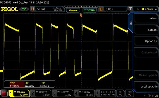
Oszilloskop Messung eines Rechtecksignals
MSO5072 Wed October 15 11:27:20 2025 RIGOL 500us 4GSa/s 20Mpts Measure STOP/RUN 4.80mV Vmax1 519.59mV Vpp1 622.52mV Freq1 1.3285kHz 100mV -220mV 100mV 0.00V 100mV 0.00V 100mV 0.00V Help About Content Option list Option install Online upgrade Local
in „Mic-Signal auf Line Level mit OP-Amp?“ · Analoge Elektronik und Schaltungstechnik · · Oszi-Bilder
-
Datei
HVprog.txt
Programmer Model: STK500 Hardware Version: 2 Firmware Version Master : 2.10 Topcard : Unknown Vtarget : 5.1 V SCK period : 2.2 us Varef : 0.1 V Oscillator : 3.686 MHz avrdude: AVR device initialized and ready to accept instructions Reading | ################################################## | 100% 0.02s avrdude: Device signature = 0x1e9403 avrdude: safemode: lfuse reads as AC avrdude: safemode: hfuse reads as C1 avrdude: safemode: lfuse reads as AC avrdude: safemode: hfuse reads as C1 avrdude: safemode: Fuses OK avrdude done. Thank
in „HVProg ->RS232->PC“ · Mikrocontroller und Digitale Elektronik ·
-
Bild
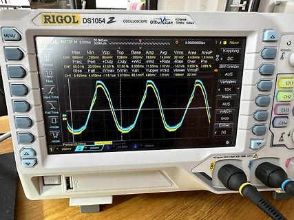
Rigol DS1054Z Oszilloskop mit Sinuswelle
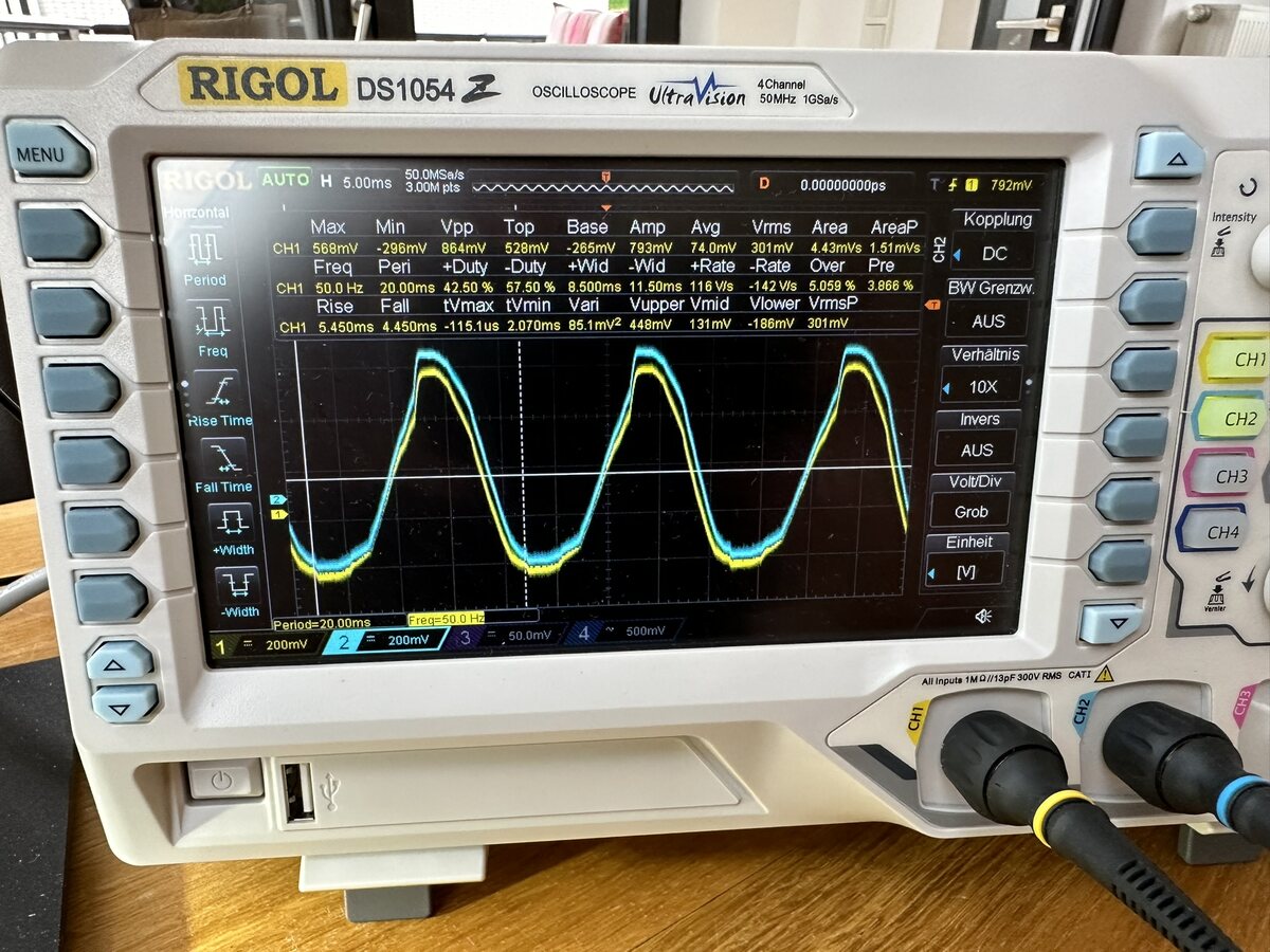
RIGOL DS1054Z OSCILLOSCOPE UltraVision 50MHz 1GSa/s MENU AUTO 50.0Ms/s 3.00M pts D 0.0000000ps CH1 568mV -206mV Vpp 528mV -265mV Base Amp 74.0mV 301mV Area 4.43us 1.51ms Kopplung DC Period 20.00ms 50.0Hz 42.50% 57.50% 8.500ms 11.50ms 116V -142V 5.059% 3.866% Rise Fall tvmax tvmin Vupper Vmid Vlower Vrms Vp Rise Time Fall Time +Width -Width Freq CH1 CH2 CH3 CH4 200mV 50.0mV
in „Couch Sensor überprüfen“ · Mikrocontroller und Digitale Elektronik · · Fotos
-
PDF
AD2500_Macro_Assembler_V402_Manual_Appendices.pdf
031 025 19 SUB 00011010 032 026 1A ESC 00011011 033 027 1B FS 00011100 034 028 1C GS 00011101 035 029 10 RS 00011110 036 030 1E US 00011111 037 031 1F SP 00100000 040 032 20 ! 00100001 041 033 21 00100010 042 034 22 # 00100011 043 035
in „2500 A.D. Z80 Macro Assembler“ · Mikrocontroller und Digitale Elektronik ·
-
PDF
IL7112_01.pdf
Specifications Min. Typ. Max. Min. Typ. Max. Quiescent Supply Current IL711 I 8 10 10 15 µA IL712 DD1 1.5 2 2.5 3 mA Quiescent Supply Current IL711 I 3.3 4 5 6 mA IL712 DD2 1.5 2 2.5 3 mA Logic Input Current I -10 10 -10 10 µA I Logic High Output Voltage V OH V DD-0.1 V DD VDD -0.1 VDD V O =-20 µA, VI=V IH 0.8*V V -0.5 0.8*V V -0.5 I = -4 mA, V =V DD DD DD DD O I IH Logic Low Output Voltage V OL 0 0.1 0 0.1 V O = 20 µA, VI=V IL 0.5 0.8 0.5 0.8 = 4 mA, O VI=V IL Switching Specifications Maximum Data Rate 100 110 100 110 MBd C = 15 pF L Pulse
in „Optokoppler mit möglichst kleinem Eingangsstrom“ · Mikrocontroller und Digitale Elektronik ·
-
Bild
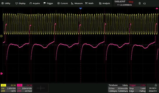
Oszilloskop-Messung zweier Signale
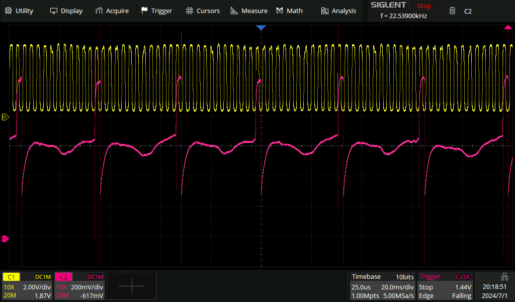
Utility Display Acquire Trigger Cursors Measure Math Analysis SIGLENT Stop C2 C1 DC1M C2 DC1M 10X 2.00V/div 10X 200mV/div 20M 1.87V 20M -617mV f = 22.53900kHz Timebase 25.0us 20.0ms/div Stop 10bits Trigger Falling C2:DC 1.44V 20:18:51 2024/7/1 1.00Mpts 5.00MSa/s Edge
in „Bastelmotor Gleichstrommotor Modell“ · Offtopic · · Oszi-Bilder
-
PDF
ISO124.pdf
= ±15V, unless otherwise noted. A S PSRR vs FREQUENCY ISOLATION LEAKAGE CURRENT vs FREQUENCY 60 100mA 54 10mA ) m 40 ( 1mA B n ( +VS1 +VS2 r 1500Vrms R u 100µA S C P –VS1 –VS2 g 20 k 10µA e L 240Vrms 1µA 0 0.1µA 1 10 100 1k 10k 100k 1M 1 10 100 1k 10k 100k 1M Frequency (Hz) Frequency (Hz) SIGNAL RESPONSE
in „Optokoppler etc“ · Mikrocontroller und Digitale Elektronik ·
-
Bild
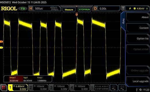
Oszilloskop-Messung einer periodischen Wellenform
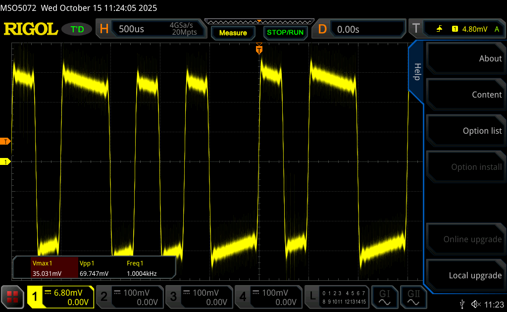
MSO5072 Wed October 15 11:24:05 2025 RIGOL T'D H 500us 4GSa/s 20Mpts Measure STOP/RUN D 0.00s T 4.80mV A Vmax1 35.031mV Vpp1 69.747mV Freq1 1.0004kHz 1 6.80mV 0.00V 2 100mV 0.00V 3 100mV 0.00V 4 100mV 0.00V L 0 1 2 3 4 5 6 7 8 9 10 11 12 13 14 15 GI GII
in „Mic-Signal auf Line Level mit OP-Amp?“ · Analoge Elektronik und Schaltungstechnik · · Oszi-Bilder
-
Bild
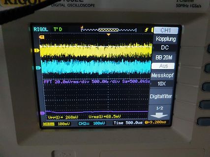
Oszilloskop-Display mit FFT-Messung
DIGITAL OSCILLOSCOPE 50MHz 1GSa/s RIGOL T'D CH1 Kopplung DC BB 20M Aus Messkopf 10X Digitalfilter 1/2 Vpp(1)=268mV Vrms(1)=68.5mV CH1 100mV CH2 100mV Time 500.0us T+9.200ms FFT 20.0mVrms/div 500.0Hz/div Sa=500.0kSa
in „Rauschen klingt nicht nach Rauschen“ · Analoge Elektronik und Schaltungstechnik · · Fotos
-
PDF
MC51F7424_V1.2.2.pdf
特性 符号 条件 最小 典型 最大 单位 工作电流 ICMP VDDA.0V - 50 100 µA 工作温度 TA -40 25 105 °C 输入失调电压 Vio Ta=25℃ - 5 10 mV 输入共模电压 Vicm - 0.1 - VDD-0.1 V 输入电流 IIN - 0 1 µA 小信号响应时间 Trs1 VDD=5V,无迟滞,正反相输入 10mV 差 - - 0.5 uS 分变化 VDD=5V, 无迟滞,正反相输入 100mV 差 大信号响应时间 Trs2 - - 0.3 uS 分变化 施密特窗口 1 Vsmt1 VDD=5V,CnSMT[1:0]=00b,双边 0 mV
in „Lidl kann auch anders (Lötstation)“ · Mechanik, Gehäuse, Werkzeug ·
-
PDF
W2000US_Data_Sheet.pdf
a live or stopped waveform Max Input Voltage 300 VRMS CAT II Position Range at 2mV/div to 200mV/div ± 2V; at >200mV/div to 5V/div ± 50V BW Limit 20MHz Input Coupling AC, DC, GND Input Impedance 1MΩ parallel with 15pF Time Base Range 5ns to 50sec/div Time Base Accuracy 50ppm Horizontal Zoom Horizontal expand or compress a live or stopped waveform Net List Price in US$, shipment free of charge within the U . 1,440.00 1,680.00 1,920.00 2,160.00 Acquisition Modes Cursors Environmental and Safety • Peak Detect • Cursors measure absolute as well as • Temperature High
-
Bild
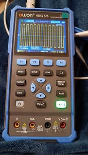
Handheld-Oszilloskop Owon HDS272S mit Rechtecksignal
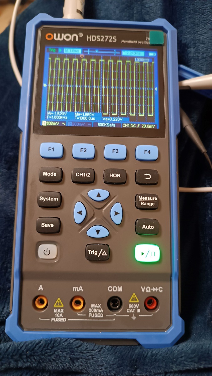
owon HDS272S Handheld oscilloscope Trig M:10ms T:2.240ms 1.000kHz Mi=1.820V Ma=1.850V F=1.000kHz T=1000.0us Vs=3.220V 500mV 200mV 500Ka/s CH1:DC f 20.0mV F1 F2 F3 F4 Mode CH1/2 HOR System Measure Range Save Auto Trig/Δ A mA COM VΩ+C MAX 10A FUSED MAX 200mA FUSED 600V CAT III
in „Induktiver Positionssensor - Fragen dazu“ · Mikrocontroller und Digitale Elektronik · · Fotos
-
PDF
Timing_AppNote__GPS.G6-X-11007_.pdf
3180 u-blox AG Phone: +65 6734 3811 E-mail: info_us@u-blox.com Phone: +41 44 722 74 44 E-mail: info_ap@u-blox.com E-mail: info@u-blox.com Support: support_ap@u-blox.com Regional Office West Coast: Support: support@u-blox.com Phone: +1 (703) 483 3184 Regional Office China: E-mail: info_us@u-blox.com Phone: +86 10 68 133 545 Technical Support: E-mail: info_cn@u-blox.com Support: support_cn@u-blox.com Phone: +1 (703) 483 3185 E-mail: support_us@u-blox.com Regional Office Japan: Phone: +
in „Frequenznormal selber bauen GPS diszipliniert 16MHz low cost ATmeg329p Assembler“ · Mikrocontroller und Digitale Elektronik ·
-
PDF
SY8105ADC.pdf
Reference REF 0.591 0.6 0.609 V Voltage I FB Input Curren FB V FB=3.3V -50 50 nA Top FET RON RDS(ON)1 40 mΩ R Bottom FET RON DS(ON)2 20 mΩ TOP FET Peak Current I Limit LIM,TOP 10 A I Bottom FET Valley LIM,BOTTOM 5.0 A Current Limit V EN Rising Threshold ENH 1.5 V EN Falling Threshold VENL 0.4 V V Input
in „Fragen Stromversorgung / Schaltplan“ · Analoge Elektronik und Schaltungstechnik ·
-
Datei
user_main.c
= adc_read(); os_delay_us(50000); // print ADC value on UART0 os_sprintf(temp," ADC value: %4d mV \r ", adc_value * 1000 / 1024 ); uart0_sendStr(temp); // ADC low LED on if (adc_value < 1) GPIO_OUTPUT_SET(GPIO_ID_PIN(4), 0);
in „Wlan2Serial Modul für 5 euro“ · Mikrocontroller und Digitale Elektronik ·
-
PDF
US-100.PDF
performs necessary processing. Specifications Input voltage: 5V DC Quiescent current: less than 2mA Level output: 5V high Level output: at the end of 0V Induction angle: not more than 15 degrees Detection distance: 2cm-450cm Precision: up to 1mm Dimensions: 4.4cm x 2.6cm x 1.4cm Weight
in „Abstandssensor US-100 seriell ansprechen?“ · Mikrocontroller und Digitale Elektronik ·
-
PDF
ATMEL-Motor_Entwicklungsboard.pdf
M P F D C 1 M T P T P _ x S P I / P P M R G V P P I M I M I _ 1 / 6 7 M M C A A A M M 5 C M C I I T 1 C P 4 / 0 9 / C 7 P 2 S K U T A B B 1 C C A D M C O C C U 5 P P D A D 2 P A D 7 / 3 S C P / 5 4 P 3
in „Stromregeler Testboard ATAVRMC100“ · Mikrocontroller und Digitale Elektronik ·
-
PDF
rgs50tsx2d-e.pdf
Rev.C RGS50TSX2D Datasheet lElectrical Characteristic Curves Fig.21 IGBT Transient Thermal Impedance 1 D = 0.5 e 0.2 n 0.1 a e p ] 0.1 I / a C m [ PDM e j h θ Single Pulse t : 0.01 1 e 0.01 0.02 t2 s Duty =1 2/t a 0.05 Peak Tj= DM×Z θ(j-cC T C1 C2 C3 R1 R2 R3 1.184m 2.063m 11.68m 63.87m 70.00m 246.1m
in „RGS50TSX2D als Ersatz für IHW20N120R3?“ · Analoge Elektronik und Schaltungstechnik ·
-
PDF
rgs50tsx2d-e.pdf
Rev.C RGS50TSX2D Datasheet lElectrical Characteristic Curves Fig.21 IGBT Transient Thermal Impedance 1 D = 0.5 e 0.2 n 0.1 a e p ] 0.1 I / a C m [ PDM e j h θ Single Pulse t : 0.01 1 e 0.01 0.02 t2 s Duty =1 2/t a 0.05 Peak Tj= DM×Z θ(j-cC T C1 C2 C3 R1 R2 R3 1.184m 2.063m 11.68m 63.87m 70.00m 246.1m
in „Induktions Doppelfeld (stand alone) - eine Seite hinüber.“ · Analoge Elektronik und Schaltungstechnik ·
-
PDF
US5668704.pdf
US005668704A Uni tedS tatesP ate nt 19 1 PaentNumber: ,668,04 Hiuchi 5 D ateofPtet: Sp.16,197 (4)SEF-ECITNGFLYBAKCONVERTR 4,577.268 atrtl..E 363/21 ,5,1. 9/1990 Higashi.er. 363/19 7) Ivno: osioigci,at,Jpn
in „Suche Schaltplan Funai D50Y-100M VCR“ · Analoge Elektronik und Schaltungstechnik ·
-
PDF
manual_XT-v.005.pdf
Road Guelph, Ontario Canada N1K 1S6 Email/Internet You may contact us through the Internet. Our email and URL addresses on the Internet are: sales@connecttech.com support@connecttech.com www.connecttech.com Note: Please go to the
-
PDF
USER_Manual_Gocator_2000-2300_S.347-348.pdf
a digital input voltage that draws 4mA to 25mA). Function Pins Min Voltage Max Voltage Min Current Max Current Min Pulse Width Trigger_in 1, 2 3.3 V 24V 3 mA 32 mA 20 us Encoder Input Encoder input is provided by an external encoder and
in „welcher Encoder“ · Analoge Elektronik und Schaltungstechnik ·
-
Datei
PWMAUDIO.ino
(80); WebSocketsServer webSocket = WebSocketsServer(81); /* gebe PWM aus 8000HZ interuppt aller 125us 1/8000Hz Sample == sample+random(-1,+1) dither */ static void inline ICACHE_RAM_ATTR outputPWM(void *pArg) {//void *pArg if (pcm_buffer.read_ptr != pcm_buffer.write_ptr) { byte sample = pcm_buffer.data
in „PWM Audio mit ESP8266, schlechte Qualitaet, -Arduino“ · Mikrocontroller und Digitale Elektronik ·
-
PDF
k9f6408u0a.pdf
23th 1999 Preliminary 0.2 Changed device name Sep. 15th 1999 Preliminary 1) KM29U64000AT -> K9F6408U0A-TCB0 2) KM29U64000AIT -> K9F6408U0A-TIB0 Changed the following items ITEM Before(M-die) After(A-die) Program Time 1,000us(Max.) 500us(Max.) Number of partial program Main
in „woher bekomme ich ein ähnliches flash/sram“ · Mikrocontroller und Digitale Elektronik ·
-
Bild
Abfotografierter Oszilloskop-Bildschirm mit Rechtecksignal
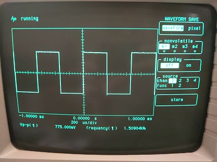
running WAVEFORM SAVE waveform pixel nonvolatile m1 m2 m3 m4 display off on source Chan 1 2 3 4 func 1 2 store -1.00000 ms 0.00000 s 1.00000 ms Vp-p(1) 775.000mV 200 us/div frequency(1) 1.50904kHz
in „[V] HP54501A Oszilloskop 100Mhz mit HP10432A Tastkopf“ · Markt · · Fotos
-
PDF
TCA9406_I2C_translator.pdf
≥ VCCA – 0.2 V CCB V OL = 1 mA, 1.65 V to 3.6 V 2.3 V to 5.5 V 0.4 V OLB VIA ≤ 0.15 V I OE 1.65 V to 3.6 V 2.3 V to 5.5 V ±1 ±2 mA A port 0 V 0 to 5.5 V ±1 ±2 mA off B port 0 to 3.6 V 0 V ±1 ±2 mA OZ A or B port 1.65 V to 3.6 V 2.3 V to 5.5 V ±1 ±2 mA 1.65 V to CCB 2.3 V to 5.5 V 2.4 I VI= VO= open, 3.6 V 0 V 2.2 mA CCA O = 0 0 V 5.5 V –1 1.65 V to CCB 2.3 V to 5.5 V 12 VI= VO= open, CCB O = 0 3.6 V 0 V –1 mA 0 V 5.5 V 1 VI= VCCI or GND, CCA
in „I2C translator tri-state“ · Mikrocontroller und Digitale Elektronik ·
-
PDF
2205.06114.pdf
5.2 Analyzing and Modifying Firmware the following, we reverse-engineer this new format, enabling us to 5.2.1 Patch Analysis Tooling. With these new insights, we can install custom patches on modern iPhones. load any patch file on top of an existing InternalBlue ROM dump 5.1.3 FirmwarePatchImageUpload
in „Windows 10, Windows 11 für "Normalnutzer" ein Witz kennt wer?“ · PC Hard- und Software ·
-
Bild
Oszilloskop-Messkurve eines Signals
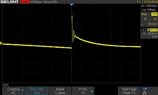
SIGLENT Stop M 50.0us/ Delay:0.00s f = 1.00993kHz Sa 1.00GSa/s Curr 700kpts Edge AC L 88.0mV 1 BAC1M 1X 20.0mV/ 0.0V CH1 Coupling AC BW Limit 20M Adjust Coarse Probe 1X Next Page Page 1/2
in „Lüfter erzeugt Störungen“ · Analoge Elektronik und Schaltungstechnik · · Oszi-Bilder
-
PDF
BUK100-50.pdf
input. SYMBOL PARAMETER CONDITIONS MIN. TYP. MAX. UNIT V IS(TO) Input threshold voltage VDS = 5 V; D = 1 mA 1.0 1.5 2.0 V IIS Input supply current normal operation; V IS5 V 100 200 350 A V = 4 V - 160 270 A 1 IS V ISR Protection reset voltage T j 25 ˚C 2.0 2.6 3.5 V T j 150 ˚C 1.0 - - IISL Input supply
in „MOSFET SCHMILZT“ · Analoge Elektronik und Schaltungstechnik ·
-
PDF
FB180SA10P.pdf
vs. Case Temperature 10000 OPERATION IN THIS AREA LIMITED BY R DS(on) R )000 V D ( DS n 10us r VGS u D.U.T. C100 100us R G a + V r - DD , 1ms I 10 V 10 10ms Pulse width ≤ 1 µs T = 25 C Duty factor ≤ 0.1 % T = 150 C J 1 Single Pulse 1 10 100 1000 V , Drain-to-Source Voltage (V) DS Fig. 8 - Maximum
in „MOSFET wird sehr heiß“ · Analoge Elektronik und Schaltungstechnik ·
-
Datei
Temp_LCD.c
<avr/delay.h> #include <lcd.h> #include <lcd.c> #include <ds18s20.c> #define ADC0 0xC0 #define ADC1 0xC1 #define ADC2 0xC2 #define ADC3 0xC3 #define ADC4 0xC4 #define ADC5 0xC5 /* FCPU = 8 MHz delays: _delay_ms = 32,77 ms _delay_us = 96,00 us */ uint8_t t; uint8_t adcmux = 0; uint16_t x = 0; uint16
in „DS18B20 + LCD + ATmega will nicht funktionieren“ · Mikrocontroller und Digitale Elektronik ·
-
PDF
avr446.pdf
^2) speed data given in 0.01*rad/sec (100 = 1 rad/sec) -------------------------------------------------------------- After the menu is shown or a command is executed the info line is shown: Motor pos: 0 a:4000 d:4000 s:2000 m:400 The demo application
in „Schrittmotor Softstart“ · Mikrocontroller und Digitale Elektronik ·
-
PDF
AVR446_Linear_speed_control_of_stepper_motor.pdf
^2) speed data given in 0.01*rad/sec (100 = 1 rad/sec) -------------------------------------------------------------- After the menu is shown or a command is executed the info line is shown: Motor pos: 0 a:4000 d:4000 s:2000 m:400 The demo application
in „rampenbrechnung für schrittmotor“ · Mikrocontroller und Digitale Elektronik ·
-
PDF
doc8017.pdf
^2) speed data given in 0.01*rad/sec (100 = 1 rad/sec) -------------------------------------------------------------- After the menu is shown or a command is executed the info line is shown: Motor pos: 0 a:4000 d:4000 s:2000 m:400 The demo application
in „Atmel Appnote AVR446 Hilfe lineare Geschwindigkeit“ · Mikrocontroller und Digitale Elektronik ·
-
PDF
AVR446.pdf
^2) speed data given in 0.01*rad/sec (100 = 1 rad/sec) -------------------------------------------------------------- After the menu is shown or a command is executed the info line is shown: Motor pos: 0 a:4000 d:4000 s:2000 m:400 The demo application
in „Atxmega Timer“ · Mikrocontroller und Digitale Elektronik ·