-
 Bild
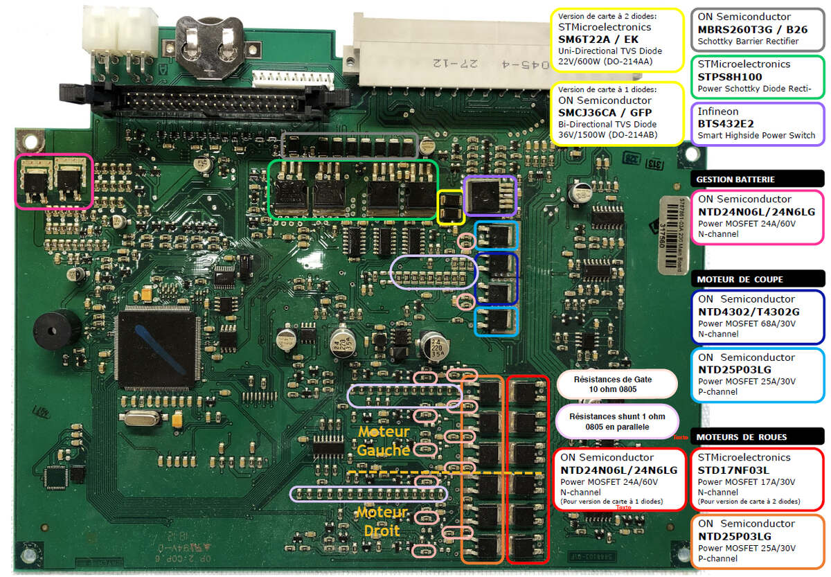
Leiterplatte mit Bauteilbeschriftungen und Markierungen
Infineon, BTS43E2, Smart Highside Power Switch, GESTION BATTERIE, NTD24N06L/24N6LG, Power MOSFET 24A/60V, N-channel, MOTEUR DE COUPE, NTD4302/T4302G, Power MOSFET 68A/30V, N-channel, NTD25P03LG, Power MOSFET 25A/30V, P-channel, MOTEURS DE ROUES, ST17NF03L, Power MOSFET 17A/30V, ON Semiconductor, NTD24N06L/24N6LG, Power MOSFET 24A/60V, N-channel, ON Semiconductor, NTD25P03LG, Power MOSFET 25A/30V, P-channel, Résistances de Gate 10 ohm, Résistances shunt 1 ohm 0805 en parallel, Moteur Gauche, Moteur Droit
in „Wo führt dieses Lötpad hin? Husqvarna ACX 230 Automower Leiterplatte“ · Analoge Elektronik und Schaltungstechnik · · Platinenfotos
-
PDF
DS8816A-05.pdf
are : E E E E A A C A A RoHS compliant and compatible with the current require- H G V G H P L P L P ments of IPC/JEDEC J-STD-020. 20 19 18 17 Suitable for use in SnPb or Pb-free soldering processes. BOOT1 1 15BOOT2
in „Spule auf Synchronwandler wird innerhalb sekunden brennend heiß“ · Analoge Elektronik und Schaltungstechnik ·
-
Datei
logFile.txt
/usr/X11R6/lib/modules/extensions/libGLcore.a Skipping "/usr/X11R6/lib/modules/extensions/libGLcore.a:m_debug_clip.o": No symbols found Skipping "/usr/X11R6/lib/modules/extensions/libGLcore.a:m_debug_norm.o": No symbols found Skipping "/usr/X11R6
-
PDF
Schematic.pdf
1 2 3 4 5 6 Spannungsversorgung Relaisschaltung V V V 1P 2 5 5 U2 AMS1117-3.3 3 HV.P F1 S14K275 600 + + 3 D 2*2 + 3 HV.P IN NOUT 4 A 0,4A L1 G I1.► K1 A + C5 +C3 C6 1 +C4 5 O1.▲ 7 ~ C11 C8 C9 R - 4,7µ 47µ 4,7µ 1 ROLL2 1 2 - 22µ 100n 22µ 47µ 2 Z Z 2 HV.N E
in „ESP8266 - UP-Modul zur Rolladensteuerung bzw. als Kreuzschalter für Lichtinstallationen“ · Projekte & Code ·
-
PDF
tssp40xxss1xb.pdf
to +85 °C Soldering temperature t ≤ 10 s, 1 mm from case T 260 °C sd Power consumption Tamb ≤ 85 °C P tot 10 mW Note • Stresses beyond those listed under “Absolute Maximum Ratings” may cause permanent damage to the device. This is a stress rating only and functional operation of the device at these or
in „Wasserspender mit IR Sensor“ · Mikrocontroller und Digitale Elektronik ·
-
PDF
ZXLD1366.pdf
precautions should be taken when handling and transporting these devices. The human body model is a 100pF capacitor discharge through a 1.5kΩ resistor pin. The machine model is a 200pF capacitor discharged directly into each pin. Thermal Resistance Rating Symbol Parameter TSOT25 SO-8EP U-DFN3030-6
in „Spannungsteiler zwischen Arduino und KSQ“ · Mikrocontroller und Digitale Elektronik ·
-
PDF
2097320.pdf
precautions should be taken when handling and transporting these devices. The human body model is a 100pF capacitor discharge through a 1.5kΩ resistor pin. The machine model is a 200pF capacitor discharged directly into each pin. Thermal Resistance Rating Symbol Parameter TSOT25 SO-8EP U-DFN3030-6
in „ZXLD1366 Beschaltung ADJ Pin“ · Analoge Elektronik und Schaltungstechnik ·
-
Datei
gps.txt
8 ; 0x63c <gps_transmit+0x2> UDR0 = byte; 644: 90 93 c6 00 sts 0x00C6, r25 } 648: 08 95 ret 0000064a <gps_transmit_p>: void gps_transmit_p (PGM_P address) { 64a: fc 01 movw r30, r24 uint8_t count = pgm_read_byte(address++); 64c: 9c 01 movw r18, r24 64e: 2f 5f subi r18, 0xFF ; 255 650: 3f 4f sbci r19
in „GCC inlined die ganze Zeit meine Funktionen.“ · Mikrocontroller und Digitale Elektronik ·
-
PDF
TDA1591.pdf
a I 1 T 3 I R x t i I O e s i V S L k h o E R 0 i 1 T E G Z 1 0 w = k O C T I 1 ) r 1 P A z L B 3 n a V T C k V T p r O R 9 S 6 a I 9 T T 1 1 5 d 2 P 1 L C F a A k 5 1 0 µ P T 5 r D c i E 4 u l l p D R
in „TDA 7313 input AM / FM“ · Analoge Elektronik und Schaltungstechnik ·
-
PDF
AD8221-Datenblatt.pdf
Bias Current 0.5 2 nA OverTemperature T = −40°C to +85°C 3 nA AverageTC 3 pA/°C Input Offset Current 0.3 1 nA OverTemperature T = −40°C to +85°C 1.5 nA AverageTC 3 pA/°C Rev.C | Page 5of 24 AD8221 ARMGrade Parameter Conditions
in „InAmp mit single supply möglich?“ · Analoge Elektronik und Schaltungstechnik ·
-
PDF
FYM-23881ABxxx.pdf
www.foryard.com DOT MATRIX DISPLAY FYM-23881ABxxx-xx ¡ö Typical electrical-optical characteristics curves: (A) (B) (C) (D) (2) (3) (8) (4) (1) (6) (5) (9) (10) 1.0 0.5 0 350 400 450 500 550 600 650 700 750 800 850 900 950 1000 Wavelength(nm) RELATIVE INTENSITY Vs WAVELENGTH(p) (1) - GaAsP/GaAs 655nm/Red (9) - GaAlAs 880nm (2) - GaP 570nm/Yellow Green (10) - GaAs/GaAs & GaAlAs/GaAs 940nm (3) - GaAsP/GaP 585nm/Yellow (A) - GaN/SiC 430nm/Blue (4) - GaAsp/GaP 635nm/Orange & Hi-Eff Red (B) - InGaN/SiC 470nm/Blue (5) - GaP 700nm/Bright
in „Treiberstufen High und Low side“ · Mikrocontroller und Digitale Elektronik ·
-
PDF
GPS25LPSeries_TechnicalSpecification.pdf
will provide a nominal 700 mVp-p signal into a 50 Ohm load. The pulse time measured at the 50% voltage point will be about 50 nSec earlier with a 50 Ohm load than with no load. Pin 4: TXD1 - First Serial Asynchronous
-
PDF
KmaCel_deutsch.pdf
Thermische Eigenschaften Vicat-Erweichungstemperatur DIN 53460/ISO 306 °C ≥ 75 ≥ 75 77 (Verfahren A50) Formbeständigkeit in der Wärme DIN 53461/ISO 75 °C ~ 56 ~ 63 – (Verfahren Ae) Linearer Ausdehnungskoeffizient (im Bereich von –30 °C bis +50 °C) DIN 53752 mm/mK ≤ 0,08 ≤ 0,08 ≤ 0,08 Wärmeleitfähigkeit
in „Selbstbau Digital Storage Oszilloskop“ · Mikrocontroller und Digitale Elektronik ·
-
PDF
1121ff.pdf
800 800 800 TJ= 25°C TJ= 25°C TJ= 25°C V OUT= VADJ RLOAD = 150Ω 700 700 RLOAD = 200Ω 700 LOAD = 25mA* A R LOAD= 130Ω A ILOAD= 25mA* A (600 ILOAD= 25mA* (600 (600 T T T E500 E500 E500 R R R C R LOAD= 330Ω C RLOAD = 500Ω C RLOAD= 380Ω N400 ILOAD = 10mA* N400 ILOAD= 10mA* N400 LOAD = 10mA* P P P D300 D300
in „Missgeschick passiert. Suche LDO 3.3V mit gedrehten TO92 Gehäuse“ · Analoge Elektronik und Schaltungstechnik ·
-
PDF
an988_All_Schottky_Diodes_are_Zero_Bias_Detectors.pdf
diode at 10 GHz. The top curvT 1 shows the voltage on the AvagoTechnologies 3469B DC O voltmeter. T P TUNED The other curves show the reduced output when a U0.1 LOW LEVEL resistor is placed across the meter. Note that the vEltage sensitivity is well under 1 mV/µW when the load resiAtor L V -I10 M is
in „H - Detektor mit vorspannen von Dioden?“ · HF, Funk und Felder ·
-
PDF
MOTOR_CTL_TEST.pdf
-/Vpp I RA4/AN3/Osc2 R R RC0/AN4/C2In+ 10 CTL R8 C T RC1/AN5/C2In- 9 T C5 6 C1 8 DRV A 5 0u1 1 RC2/AN6/P1D 7 62R S 5 - Vdd RC3/AN7/P1C D 7 C2 220n, 440V, X1 E4 X RC4/C2Out/P1B 6 T E EARTH B 14 5 R 3 2 Vss RC5/Ccp1/P1A 100p PIC16F684 D3 LF1 CMT908-V1 C C 1 SW1 2 1N4148 5 4 1 SPEED+ 1 3
in „Mikrocontroller mit Nulldurchgangserkennung und TRIAC direkt“ · Mikrocontroller und Digitale Elektronik ·
-
PDF
Baldor_VS1MX_VFD_Manual.pdf
ln1 and Analog ln2. 8-6 Customizing Your Application MN762 Figure 8-4 PI Control Block Diagram (When P-08 ≠ 9) 1 d e 3 c S - d e e 0 p f e P S e 2 P R u / n o l n i o i I D P 3 0 1 t 1 e p - e o u P p 2 8 M I t t - 0 i P 0 s P P a r p P O + + 3 3 1 P - t n i n 6 p t a a = I a G I 0 o m P P a u A S 6 - 1 t t i e 0 1 p 0 r i I - p ( l P O d n P m A - + e n e r n t 3 e tc 4 r e - R le P fe e P c S 0 1 R S 0 1 2 b P e e F 6 4 6 l e d 2 i n o e - i r 1 2 1 r r P I e u u u o C P R I I I M g g g a a a A A A MN762 Customizing
in „Frequenzumformer“ · Analoge Elektronik und Schaltungstechnik ·
-
PDF
Resources_STM32WL_UFQFPN48_REF_BOARD_Low_Power_High_Band_868-915MHz.pdf
1 2 3 4 5 6 7 8 U4E P PA0A 0 PU47 PA0 P PA1A 1 8 80PA1P 2 2 PU49 PI401 PB6 P1 PB7 PJ VDDRF VDDRF1V55 VDD VRPA P PA2A 2 10 PA2 PB2 1 POPB2B 2 J1 J2 CON1 CN22 P PA3A 3 IP00 PA3 PB3 PI41 POPB3B 3 PO 0 CT RL1 PIN101 PICN01 P
in „STM32WLE5CCU6 LoRa-Antennenendesign review“ · HF, Funk und Felder ·
-
PDF
an-978.pdf
implemented either with two n-channel MOSFETs in the totem pole configuration (source follower as a current source and common source for current sinking), or with an n-channel and a p-channel CMOS inverter stage. Each MOSFET can sink or source gate currents from 0.12 A to 4 A, depending on the MGD.
in „Isolierter High-Side Mosfet Treiber“ · Analoge Elektronik und Schaltungstechnik ·
-
PDF
ir2110-app-note.pdf
implemented either with two n-channel MOSFETs in the totem pole configuration (source follower as a current source and common source for current sinking), or with an n-channel and a p-channel CMOS inverter stage. Each MOSFET can sink or source gate currents from 0.12 A to 4 A, depending on the MGD.
in „[Transistor Ansteuerung] Ausgang kein Rechteck?“ · Analoge Elektronik und Schaltungstechnik ·
-
PDF
an-978.pdf
implemented either with two n-channel MOSFETs in the totem pole configuration (source follower as a current source and common source for current sinking), or with an n-channel and a p-channel CMOS inverter stage. Each MOSFET can sink or source gate currents from 0.12 A to 4 A, depending on the MGD.
in „high-side gate driver mit LT-Spice simulieren“ · Analoge Elektronik und Schaltungstechnik ·
-
PDF
an-978.pdf
implemented either with two n-channel MOSFETs in the totem pole configuration (source follower as a current source and common source for current sinking), or with an n-channel and a p-channel CMOS inverter stage. Each MOSFET can sink or source gate currents from 0.12 A to 4 A, depending on the MGD.
in „Halbbrücke Gate-Treiber Erklärung“ · Analoge Elektronik und Schaltungstechnik ·
-
PDF
an-978.pdf
implemented either with two n-channel MOSFETs in the totem pole configuration (source follower as a current source and common source for current sinking), or with an n-channel and a p-channel CMOS inverter stage. Each MOSFET can sink or source gate currents from 0.12 A to 4 A, depending on the MGD.
in „H-Brücke mit 100% Duty-Cycle“ · Analoge Elektronik und Schaltungstechnik ·
-
PDF
SeikoChar.pdf
= 0 º - 750 800 msec Brightness L IF=120mA* - 40 50 cd/m² toff (fall) Ta = 0ºC, Vopr=5.9V - 600 700 msec Measuring equipment : Canon illuminater LC-4SR Anode Cathode total number of LED chips =2 x 12 = 24 pcs 16 L1642 (16 x 2) AN No.SIG-CHMO9805A
in „Display Seiko L2432 und Kontrastproblem“ · Mikrocontroller und Digitale Elektronik ·
-
PDF
si86xx-1Mbps-datasheet.pdf
Width 0.60 Y1 Pad Length 1.55 Notes: 1.This Land Pattern Design is based on IPC-7351 pattern SOIC127P600X165-16N for Density Level B (Median Land Protrusion). 2.All feature sizes shown are at Maximum Material Condition (MMC) and a card fabrication tolerance of 0.05 mm is assumed. Skyworks Solutions,
in „Glavannisch Getrennter Analog Ausgang fürn PIC“ · Mikrocontroller und Digitale Elektronik ·
-
PDF
L6562N_PFC__STM.pdf
power MOSFET’s and IGBT’s with a peak current of 600 mA source and 800 mA sink. The high-level voltage of this pin is clamped at about 12V to avoid excessive gate voltages in case the pin is supplied with a high Vcc. 8 Vcc Supply Voltage
in „PFC Controller (L6562) statt normalem SNT ControllerSNT“ · Analoge Elektronik und Schaltungstechnik ·
-
PDF
MPQ4210_r1.1_MPS.pdf
50 ( B 50 ( ( 0 0 E ( 0 0 I S N S G -50 H A -50 A -20 P G-20 P -100 -100 -40 -40 -150 -150 -60 -200 -60 -200 1000 10000 100000 1000000 1000 10000 100000 1000000 FREQUENCY (Hz) FREQUENCY (Hz) Bode Plot Thermal Rise VOUT= 20V, OUT= 3A, BW = 2.3kHz
in „Controlling DC DC converter with STM32“ · Analoge Elektronik und Schaltungstechnik ·
-
PDF
PSS15NC1FT.pdf
INVERTER PART Limits Symbol Parameter Condition Min. Typ. Max. Unit Collector-emitter saturation C = 15A, Tj 25°C - 1.50 2.20 V CE(sat) voltage V DV DB = 15V, V IN5V I = 15A, T= 125°C - 1.80 2.45 V C j V EC FWDi forward voltage V IN0V, -IC= 15A - 2.40 3.10 V ton 1.10 1.90 2.60 μs tC(on) V CC600V, V = D
in „ein echter Monsterchip“ · Offtopic ·
-
PDF
ad620.pdf
Voltage Noise, e no 72 100 72 100 72 100 nV/√Hz RTI, 0.1 Hz to 10 Hz G = 1 3.0 3.0 6.0 3.0 6.0 μV p-p G = 10 0.55 0.55 0.8 0.55 0.8 μV p-p G = 100–1000 0.28 0.28 0.4 0.28 0.4 μV p-p Current Noise f = 1 kHz 100 100 100 fA/√Hz 0.1 Hz to 10 Hz 10 10 10 pA p-p REFERENCE INPUT R IN 20 20 20 kΩ IIN VIN+VREF
in „Probleme mit AD620 EKG“ · Analoge Elektronik und Schaltungstechnik ·
-
PDF
PCA9532.pdf
1 A C input/output capacitance - 2.6 5 pF io Select inputs A0, A1, A2; RESET V IL LOW-level input voltage 0.5 - +0.8 V V IH HIGH-level input voltage 2.0 - 5.5 V ILI input leakage current 1 - +1 A C input
in „[V] 5St. 16-bit I2C-bus LED dimmer Treiber NXP PCA9532 (6€)“ · Markt ·
-
PDF
PCA9532.pdf
1 A C input/output capacitance - 2.6 5 pF io Select inputs A0, A1, A2; RESET V IL LOW-level input voltage 0.5 - +0.8 V V IH HIGH-level input voltage 2.0 - 5.5 V ILI input leakage current 1 - +1 A C input
in „[V] 10St. SMD 16-bit I2C LED Treiber NXP PCA9532PW (TSSOP24) (12€)“ · Markt ·
-
PDF
PCA9532.pdf
1 A C input/output capacitance - 2.6 5 pF io Select inputs A0, A1, A2; RESET V IL LOW-level input voltage 0.5 - +0.8 V V IH HIGH-level input voltage 2.0 - 5.5 V ILI input leakage current 1 - +1 A C input
in „[V] 5St. 16-bit I2C-bus LED dimmer Treiber NXP PCA9532 (6€)“ · Markt ·
-
PDF
PCA9532.pdf
1 A C input/output capacitance - 2.6 5 pF io Select inputs A0, A1, A2; RESET V IL LOW-level input voltage 0.5 - +0.8 V V IH HIGH-level input voltage 2.0 - 5.5 V ILI input leakage current 1 - +1 A C input
in „[V] 10St. SMD 16-bit LED I2C Treiber NXP PCA9532D (SO24)“ · Markt ·
-
PDF
PCA9532.pdf
1 A C input/output capacitance - 2.6 5 pF io Select inputs A0, A1, A2; RESET V IL LOW-level input voltage 0.5 - +0.8 V V IH HIGH-level input voltage 2.0 - 5.5 V ILI input leakage current 1 - +1 A C input
in „[V] 10St. SMD 16-bit I2C LED Treiber NXP PCA9532PW (TSSOP24)“ · Markt ·
-
PDF
PCA9532.pdf
1 A C input/output capacitance - 2.6 5 pF io Select inputs A0, A1, A2; RESET V IL LOW-level input voltage 0.5 - +0.8 V V IH HIGH-level input voltage 2.0 - 5.5 V ILI input leakage current 1 - +1 A C input
in „[V] 5St. SMD 16-bit LED I2C Treiber NXP PCA9532D (SO24) (8€)“ · Markt ·
-
PDF
PCA9532.pdf
1 A C input/output capacitance - 2.6 5 pF io Select inputs A0, A1, A2; RESET V IL LOW-level input voltage 0.5 - +0.8 V V IH HIGH-level input voltage 2.0 - 5.5 V ILI input leakage current 1 - +1 A C input
in „[V] 10St. SMD 16-bit LED I2C Treiber NXP_PCA9532PW.112 (TSSOP24) (12€)“ · Markt ·
-
PDF
PCA9532.pdf
1 A C input/output capacitance - 2.6 5 pF io Select inputs A0, A1, A2; RESET V IL LOW-level input voltage 0.5 - +0.8 V V IH HIGH-level input voltage 2.0 - 5.5 V ILI input leakage current 1 - +1 A C input
in „[V] 10St. SMD 16-bit LED I2C Treiber NXP_PCA9532PW.112 (TSSOP24) (10€)“ · Markt ·
-
PDF
PCA9532.pdf
1 A C input/output capacitance - 2.6 5 pF io Select inputs A0, A1, A2; RESET V IL LOW-level input voltage 0.5 - +0.8 V V IH HIGH-level input voltage 2.0 - 5.5 V ILI input leakage current 1 - +1 A C input
in „[V] 10St. SMD 16-bit LED I2C Treiber NXP_PCA9532PW.112 (TSSOP24) (12€)“ · Markt ·
-
PDF
hoka.pdf
Switzerland HOKAszris presentedAscurrent probe based on this principlehas been realized. It was designedfor a currentrof 200A. The probeincor- poratestwodifferentsensors:aHallsensorandan aircoil. DCcurrents 111. ROGOWSK COIL with a relativeerror 5%.with a dddof2.5kA/p have been measured Transformersandtheirmagneticalcouplingare
in „100kHz Signal analog einlesen (16bit) und verarbeiten“ · Digitale Signalverarbeitung / DSP / Machine Learning ·
-
PDF
Disassembler8048_mc1981.pdf
,"INS A,BUS"09,"IN A,P1",OA,"IN A,P2" OC 170 DATA "MOVD A,P4fl,OD,flMOVD A/P5"/OE/"MOVD A,P6",OF/'MOVD A,P7" 180 DATA 10,INC &RO,11,INC &R1,15,DIS I,17,INC A,18,INC R0,19 185 DATA INC R1,1A 190 DATA INC R2,1B
in „80C48 MCS48 Assembler“ · Mikrocontroller und Digitale Elektronik ·
-
PDF
SK6812RGBW_szledcolor.pdf
/ 15 Document No.: SPC / SK6812RGBW Rev. No.: 01 w ww .zledcolr.com S h e n z h e nL E D c o lo ro p toe le c t ro n icC o .,ltd 15. White Color Temperature Ranks & CIE Color Rank (Refer to CIE 1931 chromaticity diagram ) CIE chromaticity coordinates (ANSI Cool White) C.A X Y C.A X Y C.A X Y C.A X Y
in „LED RGBW SK6812“ · Mikrocontroller und Digitale Elektronik ·
-
PDF
SK6812RGBW.pdf
/ 15 Document No.: SPC / SK6812RGBW Rev. No.: 01 w ww .zledcolr.com S h e n z h e nL E D c o lo ro p toe le c t ro n icC o .,ltd 15. White Color Temperature Ranks & CIE Color Rank (Refer to CIE 1931 chromaticity diagram ) CIE chromaticity coordinates (ANSI Cool White) C.A X Y C.A X Y C.A X Y C.A X Y
in „Planung: LED Deko-Zauberwürfel / Rubiks Cube“ · Mikrocontroller und Digitale Elektronik ·
-
PDF
LTC224210fc.pdf
R 1 2 2 . 8 μ 2 4 6 1 μF Ω Ω R 4 C . S C 0 1 9 1 9 2 J N R 4 R 4 S 0 0 F 4 Ω 1 3 5 R 0 C . 4 Ω R 0 p 5 Ω V M F R T T 0 0 R . 1 4 . R . 2 V R 6 P C R p p p p p p 9 4 C 1 4 T J X N E s s s s s s 1 1 E A O 1 2 3 P 0 0 0 0 0 0 T 0 2 F 5 C A 2 2 1 2 2 1 - C 1 Ω Ω 2 F S B 0 0 1 9 2 9 F E 3 .7 S A 0 R 4 R 4 3 . P C P R P N C 4 I 1 1 1 1 1 1 M - C 0 T V T X T G B 5 E 2 2 2 0 0 0 6 μ 7 μ T 7 C 2 1 0 - 2 1 0- C . C . 0 V 4 4 4 4 4 4 0 0 A D C C C C C C A L L L L L L T T 5 M M J S 1 μ P P P T N - B-C - E-F - - I
in „Projekt Signal-Auswertung mit High-Speed-ADC“ · Mikrocontroller und Digitale Elektronik ·
-
PDF
AN_EVAL_SEPIC_V10.pdf
s e +15V • it is easy to implement a wide input voltage V in p range (80 - 240V ) without manual switching r µC AC i or • low weight and system size A 3:0 ,& • higher efficiency compared to a linear regulator • lower stand-by power consumption
in „Feedback ohne Optokoppler möglich?“ · Analoge Elektronik und Schaltungstechnik ·
-
PDF
fronius_transpocket_1400mw_sm_de.pdf
VERFAHRENE-HANDSCHWEISSEN ÜBERPRÜFENWIG-BETRIEB V/Ampere- V/Ampere- meter meter Shunt Shunt BELASTUNG BELASTUNG (RL = 4Ω / P>100W) (RL=160mΩ/P>3,2kW) - GerätaufElektrodeschalten - GerätaufWIGschalten - Stromreglerauf5A - Strombereich I min 5A - MitI-minauf5Awennnötignachjustieren I max 140A Noteinstellung V/metere- V/Ampere
in „Fronius Schweißinverter TP 1400 Leistungsteil defekt“ · Analoge Elektronik und Schaltungstechnik ·
-
PDF
Handbuch_hager_DE_Internet.pdf
und ist somit selektiv zu einem RCD mit 30 mA. t (s) ➀ Typ A 30 mA 0,5 unverzögert 0,3 0,2 0,15 ➁ Typ A HI 30 mA 0,13 kurzzeitverzögert 0,10 ➂ i0,06 z ➂ Typ A r 300 mA ö0,05 selektiv u A ➁ 0,04 0,01 ➀ 0 I∆n (mA) 22 30 60 100 150 300 600 1500 unverz
in „20A nach 25A“ · Haus & Smart Home ·
-
PDF
STP15N80K5.pdf
Eoss V DS (µJ) (norm) 1.1 ID= 1mA 12 1.06 8 1.02 0.98 4 0.94 0 0.9 0 200 400 600 VDS(V) -75 -25 25 75 125 TJ(°C) Figure 18. Maximum avalanche energy vs temperature $0▯▯▯▯▯Y▯ ($6 ▯P-▯ ' ▯▯$ ▯▯▯ 9'' ▯▯▯9 ▯▯ ▯▯ ▯ ▯ ▯▯ ▯▯ ▯▯ ▯▯▯ ▯▯▯ 7-▯
in „1500V 8A mit MOSFET schalten“ · Analoge Elektronik und Schaltungstechnik ·
-
PDF
mXszytx.pdf
Output Ripple Noise Vin=90~274V, I =O.2~2A MAX 150 MAX 150 P-P Figure in ○=Terminal Sign Fig1. Measurement Circuit Fig2. Output Voltage/Current Copyright & Copy;2000 Shindengen Electric Mfg.Co.Ltd 0 1 0 1 e n a 0 e 0 p 1 I a r e 1 T 0 ] t 1 [ i t s e a i T - T 1 0 8 2 - A 1 M - 1 - 0 0 0 1 1 1 1 0 1 1 0 . 1 ] / C°[ )tj θ ecnadep m I l ar ehTt ni snr T 0 MA2820 Forward Bias SOA 10 150 s 50 s P limit T S/B limit 1 ] [ I t e r u r t e o C 0.1 Tc = 25°
in „Sony EV p300E (SR-535) - Schaltnetz defekt (AC/DC - Wandler)“ · Analoge Elektronik und Schaltungstechnik ·
-
PDF
858D_RevEng_Schematic.pdf
1 2 3 4 5 6 7 8 Heater (Red) Heater (Re ) R23 P22 PR0 A P1 360R A R25 U2 51R 4 1 P P2 PI20 PIU01 PI20 PIU02 P818 PR0 Q1 Heater Driver PQ0 PI20 PIU03 270R 5V0 BTA08-600C1 P PR 3041 P P1 Chassis C15 R24 C10 C2 Mains L (Red1 1 Mains_L 10n 330R 47u 100n
in „Heißluftlötstation für Gelegenheitsgebrauch“ · Mechanik, Gehäuse, Werkzeug ·
-
PDF
Beschreibung.pdf
TFT display is used: • Don't buy the rotary switch S5. • Buy 1 tactile switch. • Don't buy LED1. If a part is out of stock at Conrad, take the alternative, see below: Conrad number / QtyValue Parts Descriptionalternative 3 100nF C1, C4, C5 Capacitor 531855-89 2 22pF C2, C3 Capacitor 457167-89 1 100nF
in „Nach dem Trafo, nun die Punktschweißmaschine“ · Mechanik, Gehäuse, Werkzeug ·