-
PDF
Fehler_Parabel.pdf
∆t V ―― V ⎝s1,h1,h2,α ⎠∆s +1 ―― V ⎝s1,h1,h2,α ⎠∆h +1 ―― tV⎝s1,h1,h 2α ⎠∆h +2 ―― V ⎝s1,h1,h2,α ⎠∆α ds1 dh 1 dh2 dα ∆t VD ⋅∆1 +D 1∆h 2D ⋅∆h1+D 3∆α 2 4 2 2 2 2 2 2⋅s 1 g -2⋅v 1 ⋅ gcos α ) ⋅tan α ) 2⋅s1⋅g-2⋅v 1 ⋅cos (α) ⋅tan α) D 1 ――――――――――――――――――――――――― ―――――――――――――――――――――――――――――― - ‾‾‾2‾‾2‾‾‾‾‾‾
in „Fehlerberechnug“ · Offtopic ·
-
PDF
Tiny_AVR_2_Family.pdf
voltage range: 1.8V to 5.5V you to create extremely compact and cost-efficient designs. • Available in 14, 20 and 24 pins • 14-pin (SOIC, TSSOP), 20-pin (SOIC, SSOP, VQFN), Key Features 24-pin VQFN • Temperature ranges: –40°C to +85°C (standard) and • High-performance low-power AVR CPU with multiple clock
in „Neue 8-Bit Tinys vorgestellt: 417/814/816/817“ · Mikrocontroller und Digitale Elektronik ·
-
PDF
Seagate-Constellation-2-Datasheet.pdf
Typical Seek (bels) 2.8 2.8 2.8 2.8 2.8 Physical Z Height (mm) 15 15 15 15 15 Height (in/mm) 0.583/14.8 0.583/14.8 0.583/14.8 0.583/14.8 0.583/14.8 Width (in/mm) 2.76/70 2.76/70 2.76/70 2.76/70 2.76/70 Depth (in/mm) 3.957/100.5 3.957/100.5 3.957/100.5 3.957/100.5 3.957/100.5 Weight (lb/kg) 0.441/0.200
in „Benutzen SATA Platten die 3,3V auch?“ · PC Hard- und Software ·
-
PDF
colorlcd.pdf
0.043uf U0 r 0 a C1 l 1 a 3 m i a 8 7 6 5 4 3 2 LCD1 s k R D RL K AD ST . o © L SI C AG CE w N V O DS S R w VV w 96x65 pixeFront View Nokia 3510i COLOR lcd Epson S1D15G14 Epson S1D15G14
-
PDF
Wohnraumuhr1_Rev1.1.pdf
X2-1 + 4 5 1N4001 C5 C6 GND C7 GND TC X2-2 1000µ/25V 100n 100n DS1620 AK500 GND GND GND GND GND GND 1 2 3 4 5 6 ELV_DC2_91610DCF2 DCF1 + Sig.- C8 1 3 10µ/16V D2 D3 D4 D5 0 0 0 0 0 0 0 0 0 8 8 8 8 8 8 8 6 6 2 6 6 6 6 6 6 6 6 6 6 6 6 0 6 5 0 2 1 6 7 0 9 7 2 5 7 6 1 1
in „wohnraumuhr 2 - leiterplatte nach projekt scott huehn“ · Mikrocontroller und Digitale Elektronik ·
-
PDF
UC1701.pdf
C56 C40 C17 C1 D1 09H C10 C58 C55 C39 C16 --- D2 0AH C11 C59 C54 C38 C15 --- D3 0BH C12 C60 C53 C37 C14 --- 0001 Page 1 D4 0CH C13 C61 C52 C36 C13 --- D5 0DH C14 C62 C51 C35 C12 --- D6 0EH C15 C63 C50 C34 C11 --- D7 0FH C16 C64 C49 C33 C10 --- D0 10H C17 C1 C48 C32 C9 --- D1 11H C18 C2 C47 C31 C8 --- D2
-
PDF
lm3421.pdf
capacitor to PGND. Connect to the drain of the main N-channel MosFET switch for R DS- 17 13 IS Main Switch Current Sense sensing or to a sense resistor installed in the source of the same device. Connect the low side of all external resistor dividerINUVLO, OVP) 18 14 RPD Resistor Pull
in „Spule Dimensonierung Schaltnetzteil“ · Analoge Elektronik und Schaltungstechnik ·
-
PDF
Schaltplan_Mikrocontroller.pdf
A11 A11 25 A11 GND A12 2 A12 VCC A12 4 A12 A12 4 A12 GND A1326 A13 1 A13 28 A13 A13 28 A13 GND VCC A14 1 EEPROM A14 3 VPD A14 29 A14 28 2 J8 A15R 31 A14 A15F 3 A14 3 /CR2 20 VCC A16R 2 A15 30 A16F 2 A15 /RDR 22 CE C7 RAM A16 CE 32 A17F 30 A16 VCC U7 CAN+ 2 JP6 RD 100n VCC A17 JP1X3 /WR-U 27 WR GND 14
in „Hilfe bei PWM Signal und Hardware nötig!“ · Mikrocontroller und Digitale Elektronik ·
-
PDF
ISP1160_PHI.pdf
output D12 13 I/O bit 12 of bidirectional data; slew-rate controlled; TTL input; three-state output D13 14 I/O bit 13 of bidirectional data; slew-rate controlled; TTL input; three-state output DGND 15 - digital ground D14 16 I/O bit 14 of bidirectional data; slew-rate controlled; TTL input; three-state output
in „USB Host Controller (ISP1160) an StrongARM 1110 anbinden“ · Mikrocontroller und Digitale Elektronik ·
-
Datei
All.txt
MICROCONTROLLER 2 IC4 MAX232 MAX232 DIL16 RS232 TRANSEIVER 2 IC4 MAX232 MAX232 DIL16 2 IC4 LM324N LM324N DIL14 OP AMP 2 IC4 DS1307 DS1307 SO8 2 IC4 78XXL 78XXL VOLTAGE REGULATOR 2 IC4 7805 78XXL 78XXL VOLTAGE REGULATOR 2 IC4 74HC573N 74HC573N DIL20 8-bit D latch BUS DRIVER 2 IC4 74ACT164N 74ACT164N DIL14 8-bit
in „[KiCad] Bibliotheksaufbau - Konzeptideen gesucht“ · Platinen ·
-
PDF
ACB_Datasheet_premininary.pdf
Data sheet AKKON USB Contrtoller Board DS001 AKKON USB CONTROLLER BOARD Development board with the PIC18F4550™* Datasheet 16bit Microcontroller board with USB Authors: Gerhard Burger Version: 1.0 Last update: 19.10.2005 File: Attachments: no
in „interessiert an einem PIC18 USB controller board?“ · Markt ·
-
PDF
ACB_Datasheet_premininary.pdf
Data sheet AKKON USB Contrtoller Board DS001 AKKON USB CONTROLLER BOARD Development board with the PIC18F4550™* Datasheet 8bit Microcontroller board with USB Authors: Gerhard Burger Version: 1.0 Last update: 19.10.2005 File: Attachments: no
in „interessiert an einem PIC18 USB controller board?“ · Markt ·
-
PDF
FAG_BBRTS_bk_rev_SCH.PDF
R2 +5V 1 2 K3 R-0402 1 U1 +5Vout Type +5V +5V DS1845ausgezeichnet K8 1 6sed 1NC VCC 5 CLK 2 +5Vout 2A Y 4 2 4 C18 2 GND 3 1 0 0 1 5 2 - 0 C R 1 R 1 2 - 2 K10 C NC7S14P5X k R16 C-0402 1 0 R24 5 2 5 1 U8a GND 2 4 3 t 1 2 3 1 15k 2 0 o R-0402 - 22k 2
in „Ebike Drehmoment-Sensor auswerten“ · Fahrzeugelektronik ·
-
PDF
AIC1896.pdf
1KΩ ILED E74 R1 72 C2 62 L: GTSK-51-150M (15µH) 70 L: GTSK-51-100M (10µH) 0.033µF 68 2 4 6 8 10 12 14 16 18 20 LED Current (mA) Fig. 1 Li-Ion Powered Driver for three white LEDs Analog Integrations Corporation Si-Soft Research Center DS-1896G-01 121208 3A1, No.1, Li-Hsin Rd. I, Science Park, Hsinchu
in „Stepup von 5V auf 12V mit AIC1896“ · Analoge Elektronik und Schaltungstechnik ·
-
PDF
Output.PDF
1 2 3 4 Pic.SchDoc U3 RC0 P11ER14 15 A RC2 PIURCLQB2U3015 A RC4 QD4U303 Analog V16 QF6U305 P13RCLQH9U307 PIGND8H'IU309 GNDN74HC595D U4 3ULM332AR2VCC P11ER14 15 PIVADJ+IP2.2k201 PIURCLQB2U4015 GND 1 QD4U403 B V16 QF6U405 B P13RCLQH9U407
in „Schaltungsüberprüfung“ · Mikrocontroller und Digitale Elektronik ·
-
PDF
Schaltplan.pdf
GND GND 3.3V 3.3V 3.3V SV1 DS3231 K K 40 39 TEN15-2411WI 3 0 4 0 38 37 1 16 SCL R 1 R 1 36 35 32KHZ SCL 34 33 2 15 SDA 32 31 12V GND VCC VCC VCC SDA 30 29 E 3 INT VBAT 14 VBAT 28 27 T 26 25 O 4 RST GND 13 24 23 E + C1 3.3V 22 21 R 5 12 20 19 3300uf P$1 P$8 18 17 6 11 16 15 P$2 P$7 C2 14 13 LSP4 +VIN -VIN -VOUT +VOUT REMOTE 7 P$3 P$6 10 12 11 GND 100nF 10 9 8 P$4 P$5 9 VCC 8 7 SHUTDOWN 6 5 SCL 4 3 SDA GND GND GND 2 1 Zeitgeber N W 12V 5.0V 5.0V D T U 12V GND 12V U1 S IN OUT 8 1 GND +
in „Raspi Shield - so in Ordnung?“ · Mikrocontroller und Digitale Elektronik ·
-
PDF
netgear-fs108-benutzerhandbuch.pdf
and throughput. The Model FS108 switch can segment networks that are built with the NETGEAR Model DS108 Dual Speed Hubs. Model FS108 switch FAST ETHERNET S100 Mbps LINK Rx 1 2 3 4 5 6 7 8 Power Collision 1 2 3 4 5 6 7 8 Model DS108 hub Model DS108 hub Auto 10/1DUAL SPEED Auto 10/1DUAL SPEED 8903FA Extending
in „[V] Netgear 8-fach Switch FS 108 + 18 Stk. Netzwerk-/Patchkabel“ · Markt ·
-
PDF
Support-Schematic.PDF
3.3V Iope11 1 2 Iope12 5V 5V Ial2011 2 Iale02 5V SN74HC595 Header 5X2 CHESS-RESERVED Iope13 3 4 Iope14 5V 5V PICabl3203 4 PICable2045V GND 5V GND SCR-RESERVED Iope15 5 6 Iope16 GND 3.3V PICabl5205 6 PICable2063.3V R2 I1 31 R1 P1 SCR-RS Iope17 Iope181-8 PICable207 PICable208 I 11 5V R11 R22 R33 R44 R55
in „Zufällige Ausgangsspannungen bei TXB0108PWR“ · Mikrocontroller und Digitale Elektronik ·
-
PDF
am29dl323db.pdf
Address Y a o L C OE# BYTE# 4 Am29DL322D/323D/324D December 13, 2005 CONNECTION DIAGRAMS A15 1 48 A16 A14 2 47 BYTE# A13 3 46 VSS A12 4 45 DQ15/A-1 A11 5 44 DQ7 A10 6 43 DQ14 A9 7 42 DQ6 A8 8 48-Pin Standard TSOP 41 DQ13 A19 9 40 DQ5 A20 10 39 DQ12 WE# 11 38 DQ4 RESET# 12 37 VCC NC 13 36 DQ11 WP#/ACC 14
in „55 Stk. Flashbausteine 32Mbit, TSSOP48, 3,3V AM29DL323DB-90“ · Markt ·
-
PDF
ET0700G0DM6-EMERGINGDISPLAY.pdf
TIA poa to MODENO. fr Cor ria NF E i(RoHS) 0 Gt0 D M 6 CFORMthSRSo:g uta Au cn ito yTe ew sl iu Di ds gn nt CUSmeMERDo APPROVAL _____________________________ _____________________________ 02101300-01-02 E M E R G I N G D I S P L A Y MODEL NO. VERSION PAGE TECHNOLOGIES CORPORATION E T 0 7 0 0 G 0 D M
in „LCD Display / Controller eines Schweißgerätes prüfen“ · Mikrocontroller und Digitale Elektronik ·
-
PDF
gravity_g.pdf
g n=204 for a local gravitational acceleration on earth: n for(i=1;i<9;i++) for(j=i+1;j<10;j++) { ds1=ds[i]; ds2=ds[j];//meter dt1=dt[i]/f_cpu; dt2=dt[j]/f_cpu;//second because of T2_PS_1_1 g += 2*(ds2*dt1-ds1*dt2)/(dt2*dt2*dt1-dt1*dt1*dt2); n++; } g=g/n;//average value of g and we get for example:
in „Microchip springt auf den Arduino Zug auf“ · Mikrocontroller und Digitale Elektronik ·
-
Datei
nrf24l01.h
register address #define RX_PW_P2 0x13 // 'RX payload width, pipe2' register address #define RX_PW_P3 0x14 // 'RX payload width, pipe3' register address #define RX_PW_P4 0x15 // 'RX payload width, pipe4' register address #define RX_PW_P5 0x16 // 'RX payload width, pipe5' register address #define FIFO_STATUS
in „RFM12 vs nrf24l01“ · Mikrocontroller und Digitale Elektronik ·
-
PDF
db214_224-2_1_.pdf
normally as shown in Table 2. Internal 1M▯ pull-up resistor. 17 13 13 13 VSS Negative supply (GND) 18 14 14 14 Internal connection This pin is internally connected. Leave open circuit. 19 15 15 15 Rx Output This is the processed received audio signal output. This pin is held at a DC ‘bias’ voltage for all
in „Scrambler für PMR“ · Mikrocontroller und Digitale Elektronik ·
-
PDF
TNY256.pdf
125 135 145 °C Temperature Thermal Shutdown 70 °C Hysteresis OUTPUT TJ= 25 °C 15.6 18.0 ON-State R DS(ON) D = 50 mA Ω Resistance T J 100 °C 25.7 30.0 OFF-State I V BP= 6.2 V, EN/UV 0 V, DSS V = 560 V, T = 125 °C 50 µA Leakage DS J Breakdown BV VBP= 6.2 V, EN/UV 0 V, Voltage DSS I = 100 µA, T = 25 °C 700 V DS J tR ns Rise Time 50 Measured in a Typical Flyback Converter Application. Fall Time tF 50 ns 10 7/01 TNY256 Conditions Parameter Symbol SOURCE = 0 V; T = J40 to 125 °C Min Typ Max Units See Figure 14
in „Brauche Dringend Hilfe bei Bauteilbestimmung“ · Analoge Elektronik und Schaltungstechnik ·
-
PDF
innoswitch3-ep_family_datasheet.pdf
R DS(ON)cross temperature for a gate voltage of 4.5 V. There is a slight delay between the commencement of the flyback cycle and the turn-on of the SR FET. During this time, the body diode of the SR FET conducts
in „Fritz Repeater 2400“ · Analoge Elektronik und Schaltungstechnik ·
-
PDF
Schaltplan.pdf
ULN2803A 5V 5V 3,3V 3,3V 16 4 P0 1 18 GND 8 5 P1 2 17 A0 1 6 P2 3 16 7 A1 2 5 7 P3 4 15 A2 3 8 9 P4 5 14 F 10 P5 6 13 D2 SDA15 C 11 P6 7 12 D1 SCL 14 P 12 P7 8 11 5V + 6 INT 13 RN 10k 9 6 R8 10k 2 DC 8 3,3V 12V LED3 P R23 E 230V K3 AC 230V LED1 R3 20k D6 Z1 3,3V LED2 D7 R13 20k Z2 3,3V LED3 D8 R23 20k Z3
in „LED-Steuerung mit WLAN-Server, bistablen Relais und ZeroCrossSwitching“ · Projekte & Code ·
-
PDF
10134fd.pdf
LT1014ISW#TRPBF LT1014ISW 16-Lead Plastic SO –40°C to 85°C LT1014ACN#PBF LT1014ACN#TRPBF LT1014ACN 14-Lead PDIP 0°C to 70°C LT1014CN#PBF LT1014CN#TRPBF LT1014CN 14-Lead PDIP 0°C to 70°C LT1014DN#PBF LT1014DN#TRPBF LT1014DN 14-Lead PDIP 0°C to 70°C LT1014IN#PBF LT1014IN#TRPBF LT1014IN 14-Lead PDIP –40
in „LT1013 Unterschied D und P Package“ · Analoge Elektronik und Schaltungstechnik ·
-
PDF
21058F.PDF
Corporation Smart Serial is a trademark of Microchip Technology, Inc. 1995 Microchip Technology Inc. DS21058F-page 1 24C65 1.0 ELECTRICALCHARACTERISTICS TABLE 1-1: PIN FUNCTION TABLE 1.1 Maxim um Ratings* Name Function VCC .......................................................A0..A2.....User Configurable
-
PDF
DATASHEET_ADG333A-AD-EN.pdf
TOP VIEW 16 V DD SS DD GND 6 (Not to Scale)15 NC (Not to Scale) GND 6 15 NC GND 6 15 NC S2B 7 S2B 7 14 S3B S2B 7 14 S3B 14 S3B D2 8 13 D3 D2 8 13 D3 D2 8 13 D3 S2A 9 12 S3A S2A 9 12 S3A S2A 9 12 S3A 4 IN2 10 11 IN3 0 IN2 10 11 IN3 0 IN2 10 11 IN3 - 2 1 1 NC = NO CONNECT 1 NC = NO CONNECT 0 NC = NO CONNECT
in „IC Analog Audio Schalter“ · Analoge Elektronik und Schaltungstechnik ·
-
PDF
metex.pdf
gelöst ist, dass damit die Funktion "Auto-Sleep" abgeschaltet wird. Der ankommende String hat immer 14 Zeichen und in der Bedienungsanleitung sind zwei Beispiel angegeben. Daten 1 2 3 4 5 6 7 8 9 A B C D E Beispiel 1 D C - 3 9 9 . 9 m V \r BeispielO H 3 9 . 9 9 M O h m \r 2 Nach Bedienungsanleitung ist das Messgerät in GW-Basic folgender Weise anzusteuern. 10 OPEN "COM1:600,N,7,2.RS,CS,DS,CD" AS #2 20 A$="D" 30 PRINT '2,A$ 40 IN$=INPUT$(14,#2) 50 PRINT IN$ 60 CLOSE #2 70 END Im LabVIEW-Programm wurden die VISA Treiber verwendet. Es ist die Schnittstelle ohne Hardware Handshake geöffnet
in „Mulimeter: Gedöns mit Metex 3410“ · Mikrocontroller und Digitale Elektronik ·
-
PDF
3986pfd.pdf
Crossover Dead Time DEAD ROSC = 10 kΩ, 0.6 – 1.2 μs Pull-Up On Resistance R I = –25 mA 30 40 55 Ω DS(on)UP GH Pull-Down On Resistance RDS(on)DN GL= 25 mA 14 19 24 Ω Short-Circuit Current – Source I –140 –110 –80 mA SC(source) Short-Circuit Current – Sink SC(sink) 160 200 250 mA GHx Output Voltage V
in „Bitte Hilfe in Englisch“ · Mikrocontroller und Digitale Elektronik ·
-
PDF
3986.pdf
Crossover Dead Time DEAD ROSC = 10 kΩ, 0.6 – 1.2 μs Pull-Up On Resistance R I = –25 mA 30 40 55 Ω DS(on)UP GH Pull-Down On Resistance RDS(on)DN GL= 25 mA 14 19 24 Ω Short-Circuit Current – Source I –140 –110 –80 mA SC(source) Short-Circuit Current – Sink SC(sink) 160 200 250 mA GHx Output Voltage V
in „Schrittmotorsteuerung“ · Mikrocontroller und Digitale Elektronik ·
-
PDF
A4989-Datasheet-1.pdf
DEAD OSC Pull-Up On Resistance RDS(on)UP GH = –25 mA 30 40 55 Ω Pull-Down On Resistance R I = 25 mA 14 19 24 Ω DS(on)DN GL Short-Circuit Current – Source ISC(source) –140 –110 –80 mA Short-Circuit Current – Sink I 160 200 250 mA SC(sink) GHx Output Voltage VGHx CBOOTx fully charged VC–0.2 – – V VREG–
in „Masseflächen?“ · Platinen ·
-
PDF
tbc_de.pdf
Integer-Konstanten....................................................................................14 2.2.3 Deklaration von Datenfeldern (Arrays).............................................................................14 2.2.4 Die DEFINT-Anweisung..................................................
in „Paragraphen für alloc(..) festlegen.“ · Softwareentwicklung ·
-
PDF
K9F1G08U0B.pdf
2112byte A0~A7 A8~A11 A12~A19 A20~A27 Command Latch Cycle CLE CLS tCLH tCS tCH CE tWP WE tALS ALH ALE tDS tDH I/Ox Command Address Latch Cycle tCLS CLE CS tWC tWC WC CE tWP tWP tWP tWP WE WH WH tWH tALH tALS ALH ALS ALH tALS ALH tALS ALE tDS DH tDS tDH tDS tDH tDS tDH I/Ox Col. Add1 Col. Add2 Row Add1 Row
in „stm32 sd-card und Nand flash“ · Mikrocontroller und Digitale Elektronik ·
-
PDF
CM-BF537E_HardwareUserManual_V1.pdf
nc: MO3* 9 Vin 3V3 PWR 10 Vin 3V3 PWR 11 PG0 / PPI1D0 I/O 12 PG2 / PPI1D2 I/O 13 PG4 / PPI1D4 I/O 14 PG6 / PPI1D6 I/O 15 PG8 / PPI1D8 / DR1SEC I/O 16 PG10 / PPI1D10 / RSCLK1 I/O 17 PG12 / PPI1D12 / DR1PRI I/O 18 PG14 / PPI1D14 / TFS1 I/O 19 PPI1SY3 / PF7 / TMR2 I/O 20 PPI1SY1 / PF9 / TMR0 I/O 21 PPI1SY1
in „SDHC Karte Einbindung“ · Mikrocontroller und Digitale Elektronik ·
-
PDF
STR-W6253D_PWMswitschRegulator.pdf
Pulse A 100 100.00 ) %80 t 10.00 i 0. a f A 1m r e D 1m s g C60 t it s t g e tl (o) r t r 1.00 rr R DS p e C Cu et O D40 i du f r r S a D e 0.10 p e20 T Refer to figure 1 for MOSFET SOA temperature derating coefficient 0 0.01 0 25 50 75 100 125 150 1 10 100 1000 Temperature, F (°C) Drain-to-Source VoltageDS
in „suche Diode aus Schaltnetzteil“ · Analoge Elektronik und Schaltungstechnik ·
-
PDF
STR-W6253D_PWMswitschRegulator.pdf
Pulse A 100 100.00 ) %80 t 10.00 i 0. a f A 1m r e D 1m s g C60 t it s t g e tl (o) r t r 1.00 rr R DS p e C Cu et O D40 i du f r r S a D e 0.10 p e20 T Refer to figure 1 for MOSFET SOA temperature derating coefficient 0 0.01 0 25 50 75 100 125 150 1 10 100 1000 Temperature, F (°C) Drain-to-Source VoltageDS
in „Reparatur Audio-Schaltnetzteil“ · Analoge Elektronik und Schaltungstechnik ·
-
PDF
_C-Versuchsboard_Schaltplan.pdf
7 3 A 4K7 R Q7D B D X2-3 A R29 BC817 2 L V P 2 GND V 5 K3 X2-2 100K 5 R11 GND 0 + 1G6RW S O 1 SV1 14 2 + S X2-1 R28 D07 +VCC 4K7 3 3 A D 6 5 13 D06 DS1 R 1Q6 B 2 E MSTBV3 4 3 100K 12 D05 DMC20481 3 3 BC817 L 5 3 X3-3 2 1 11 D04 VLCD 3 2 R R10 GND 0 + K1 5 R27 4 RS 4 1G6RW P 2 X3-2 + 6 E 0 0 0 0 - -
in „Problem mit ATmega32“ · Mikrocontroller und Digitale Elektronik ·
-
PDF
cassegrain01.pdf
Fe Xe Ye Fc (mm) 180,0000 34,6314 83,0702 -100,0000 19,5658 429,6068 131,3 -475 967,0202 58,33 -475 Ds Sub ref dia (mm) 200,0000 34,6314 83,0702 -92,0000 17,0443 429,6068 117,84 -450 967,0202 52,35 -450 Dm Dia main Dish (mm) 1210,0000 34,6314 83,0702 -84,0000 14,6197 429,6068 105,11 -425 967,0202 46,7
in „Suche Wellen Adapter "ding" ?“ · Mechanik, Gehäuse, Werkzeug ·
-
PDF
CAN_uC_V2_01Jan2013_Stromlauf.pdf
B CM2N N N N N N N N ODER R 1 2 Q1 2 C C V R R n A A A A A A A A 4 3 2 1 4 3 2 1 4 3 2 1 32,768KHz DS18B20 GND FM24V10 FRAM GND GND 1 1 4 C GND GND C 2 1 K3 K1X15 1 2 3 4 5 6 7 8 9 10 11 12 13 14 15 5 6 7 8 5 6 7 8 5 6 7 8 0 1 R 2 R GND-Insel, GND an VSS 7 8 9 1 GND-Insel R 1 N 0 1 C 1 C 1 C 1 C unter
in „Anforderungssammlung CAN Hausbus mit PIC µC“ · Haus & Smart Home ·
-
PDF
LGP42-10LF_EAY60869402_PLHF-L923A.pdf
FEELUX LIENCHANG MF72-2.5D15 NSE 72 3 2 Pcs TH600 TH601 THERMISTOR DSC2.5D15 DSC 73 3 1 Pcs VA100 INR14D621K(7.5mm),073C( BLACK TUBE) VARISTOR AMOTECH SVC621D-14A,073C( BLACK TUBE) SAMHWA PILKOR SAMSUNG 74 4 11 Pcs C207 C213 C230 C303 C305 C312CAP FLAT 100NF K 50V X7R(2012) CAPACITOR-SMD TDK C324 C502
in „LG Inverter Kapazitator abgebrannt“ · Analoge Elektronik und Schaltungstechnik ·
-
Datei
MENUE_Interrupt-Abfrage_Anzeige_Deklarierung.bas
Echtzeituhr Ddrd = &HFE Ddrb.1 = 1 Config Sda = Portc.1 ' I2C Bus konfigurieren Config Scl = Portc.0 Const Ds1307w = &HD0 ' Addresse der Ds1307 Uhr Const Ds1307r = &HD1 Config Clock = User '' Interne Time/Date Routinen für Bascom konfigurieren Config Date = Dmy , Separator = . ' *********** Konfiguration Ende
in „RXC Interrupt Problem ( Bascom)“ · Mikrocontroller und Digitale Elektronik ·
-
PDF
WZU-Rev1.3.pdf
PD5 18 10µ/16V (OC1B)PD4 17 R6 (INT1)PD3 16 R8 3k D N (INT0)PD2 15 1k N G (TXD)PD1 0V G A (RXD)PD0 14 TR1 R5 +5V R9 BC548B MEGA8535-P 1 750 10k 1 3 IC4 1 DQ VDD 8 KK1 0V 0V 0V PR1935 2 CLK TH 7 D +5V D D1 78S05 3 6 RST TL X2-1 + IN OUT 4 5 1N4001 C5 C6 GND C7 GND TC X2-2 1000µ/25V 100n 100n AK500 DS1620
in „ELV - DCF Großuhr ELV9991 alias ZILOG Z86E0812PSC“ · Mikrocontroller und Digitale Elektronik ·
-
PDF
EA8252.pdf
voltage range. Built-in low R high/low side Power-MOSFETS not only reduce external components and has DS(ON) up to 95% efficiency, ideal for 2A output current applicatiThe EA8252 is designed to take into account the light load mode operation. At output loading 10mA condition, the efficiency up to 81%. The
in „Kurioser DC-DC Step Down Converter“ · Analoge Elektronik und Schaltungstechnik ·
-
Datei
nrf24l01.h
register address #define RX_PW_P2 0x13 // 'RX payload width, pipe2' register address #define RX_PW_P3 0x14 // 'RX payload width, pipe3' register address #define RX_PW_P4 0x15 // 'RX payload width, pipe4' register address #define RX_PW_P5 0x16 // 'RX payload width, pipe5' register address #define FIFO_STATUS
in „RFM12 vs nrf24l01“ · Mikrocontroller und Digitale Elektronik ·
-
PDF
MSi001_R3v2.0.pdf
4 x BW /2 100 Reg. 0: D[16:14] = 011 1050 1,2 Differential Group D[16:14] = 100 380 ns Delay D[16:14] = 101 320 D[16:14] = 110 270 D[16:14] = 111 240 Reg. 0: D[16:14] = 011 77 Maximum base- D[16:14] = 100 69 dB band voltage gain D[16:14] = 101 67.5 D[16:14] = 110 66 D[16:14] = 111 65 3 O/P clipping level 3 Vp-p diff Reg. 1 O/P residual DC offset D[17:14] = 0101, 50 mV D[17:14] = 1101 5 I/Q amplitude imbalance All gain settings 1 dB
-
 Bild
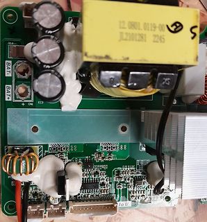
Nahaufnahme einer Leiterplatte mit Transformator und Kondensatoren
To BAT- BAT+ EC3 CN1 HS1 HS2 12.0801.0119-00 JL2101281 2245 U14 R6 R11 R4 DS C14 R22 R23 R25 R26 R27 R28 R29 R30 R31 R32 R33 R34 R35 R36 R37 R38 R39 R40 R41 R42 R43 R44 R45 R46 R47 R48 R49 R50 R51 R52 R53 R54 R55 R56 R57 R58 R59 R60 R61 R62 R63 R64 R65 R66 R67 R68
in „PDP8974 Ersatz gesucht“ · Analoge Elektronik und Schaltungstechnik · · Platinenfotos
-
PDF
Spec_Inkontinenzsensor_ATtiny461A.pdf
VCC notwendig! 13 U2 Analoger Eingang: U2, Kondensator 100nF gegen Masse E - +0 .. +VCC notwendig! 14 TAST Eingang für Taster E - „low“ aktiv) 15 VCC +1,8..+5,5V Spannungsversorgung 16 GND Masseanschluss GND 1) 17 KS8 Kodierschalter Pin 8-wertig E - „low“ aktiv 18 KS4 Kodierschalter Pin 4-wertig E -
-
PDF
LM3401.pdf
selected based on the maximum Drain- And the total power dissipated in the IC is: Source voltage (V DS), Drain current rating (Id), maximum PD = (Iq x V ) + (I x 4.7V) Gate-Source voltage (V GS), on-resistance (DS(on)), and Gate IN G capacitance. Where Iq is typically 1.05 mA and 4.7V is the typical HG
in „LM3401 LED-Treiber“ · Mikrocontroller und Digitale Elektronik ·