-
Datei
main.c
Street, Suite 900, Mountain View, California, 94041, USA. * * * testet with: * - avr-gcc 4.3.4 * - Atmega8 @ 8 MHz */ #include "main.h" #include <avr/io.h> #include <stdlib.h> #include <string.h> #include <avr/interrupt.h> #include <timeout.h> #include <util/delay.h> #include "uart.h" #include "am2302.
in „C-File Notlösung. Wer könnte kurz helfen?“ · Mikrocontroller und Digitale Elektronik ·
-
Datei
PWMVersuch.asm
;****************************************** ;* * ;* 3-Kanal PWM für Atmega 16 * ;* * ;* * ;****************************************** .include"m16def.inc" .def ac1L = r9 ; low Byte aktueller Zählerstand Kanal1 .def ac2L = r10 ; low Byte aktueller Zählerstand Kanal2 .def ac3L
in „Atmega 16 Interrups“ · Mikrocontroller und Digitale Elektronik ·
-
PDF
Hauptplatine_Schaltplan.pdf
21 AREF PD6(AIN0/OC0A/PCINT22) 12 13 DB6 A 15 PD7(AIN1/PCINT23) 13 14 DB7 K 16 GND S4 U D I C8 PB0(ICP1/CLKO/PCINT0) 14 MINIMEXLE_162A O G 100nF PB1(OC1A/PCINT1) 15 3 1 22 AGND PB2(SS/OC1B/PCINT2) 16 R3 4 2 3 PB3(MOSI/OC2A/PCINT3) 17 LED1 4,7k 8 GND PB4(MISO/PCINT4) 18 S3 PB5(SCK/PCINT5) 19 R 1 2 R4 3 1 GND ATMEGA48/88/168-PU R 6 4 2 4,7k S2 R5 3 1 2 4 6 8 1 VCC 4 2 N 2 4,7k G S 1 3 5 7 9 VCC 1N4004 D5 + D6 6 IN OUT 7 N VCC 1N4004 C G + C9 GND C12 + X1 - IC3 R 1 µ 100nF 100nF F 0 0 2 1 1 E L GND 01.12.2011 10
in „Display DEM16216 - Initialisierung falsch? - Schwarzer Balken“ · Mikrocontroller und Digitale Elektronik ·
-
PDF
untitled...pdf
- 16 38 PC3 PF2 59 VCC 17 ON/OFF AXE 18 0 2 5 1 39 PC4 PF3 58 19 SIMIO C103/TXD 20 LIS3LV02DQSMD 40 PC5 PF4 57 21 PWRMON SIMVCC 22 41 PC6 PF5 56 k 23 RESET SIMRST 24 N N N N CK 16 42 PC7 PF6 55 3 0 25 RES
-
PDF
avrcp_m_v1.pdf
A5 S 1 15 USBDP CBUS4 12 10k C3 PD6(AIN0) 12 A6 4256 2 B 2 16 USBDM 100n PD7(AIN1) 13 A7 1 S 3 TEST 26 N U 4 25 GND PB0(ICP) 14 A4 CON1'CONTROL P 7 +3V3 15 A3 CS +3V3 CON1'POWER C5 GND 18 PB1(OC1A) 16 A2 P1 #CS Vcc GND 10n GND 21 PB2(SS/OC1B) 17 A1 A1 P2 DI GND
in „CP/M auf ATmega88“ · Mikrocontroller und Digitale Elektronik ·
-
Datei
Zutrittkontrolle.bas
Zutrittskontrolle20.bas 'copyright : (c) 1995-2016, Falkner 'purpose : Zutrittskontrolle 'micro : Atmega8 'suited for demo : no 'commercial addon needed : no 'Email : 'Version : 2.0 'Release : 2.0a 'Changelog : 10.03.2016 00:29:10 'Programmer : Falkner '------------------------------------------------
in „Atmega8 Zutrittskontrolle Passwort ändern wie Tastatur“ · Mikrocontroller und Digitale Elektronik ·
-
PDF
avr_vga.pdf
4 D PC6(/RESET) PC0(ADC0) 24 12 A QH 3 2 18 R9 6 L C2 C14100n 22 PC1(ADC1) 25 13 B 2 IC7A 4 A1 Y1 16 R10 470 G 2 12 21 GND PC2(ADC2) 26 14 C 7 6 A2 Y2 14 R11 470 7 ü 100n 20 AREF PC3(ADC3) 27 3 D QH 74AC08D 8 A3 Y3 12 470 B 3 13 G AVCC PC4(ADC4/SDA) E A4 Y4 C16 PC5(ADC5/SCL) 28 4 F 4 8 Clock Switch
in „CP/M auf ATmega88“ · Mikrocontroller und Digitale Elektronik ·
-
PDF
BLSD1510.pdf
MSS1038-334KLB 1 PC5 (ADC5/SCL/PCINT13) 29 RST GND PC6 (RESET/PCINT14) GND 30 100nF IC5 PD0 (RXD/PCINT16) 31 8 1 PD1 (TXD/PCINT17) DRC SWC PD2 (INT0/PCINT18) 32 IR_PULSE PD3 (PCINT19/OC2B/INT1) 1 PWMR 7 IPK SWE 2 PD4 (PCINT20/XCK/T0) 2 PD5 (PCINT21/OC0B/T1) 9 PWMG R6 5 COMP- TCAP 3 PD6 (PCINT22/OC0A/AIN0
in „[V] RGB Steuerung“ · Markt ·
-
PDF
ledmatrix.pdf
RESET A (ADC0)PA0 R11 C12 (ADC1)PA1 39 C 1 22k 100u/10V 38 R3 Q1 82p Y1 (ADC2)PA2 330k BC547 B C1 16.000MHz (ADC3)PA3 37 2 2 D 12 36 TO-92 R8 R12 R14 X N XTAL2 (ADC4)PA4 E 3 4k7 4k7 4k7 2 1 Audio not populated (ADC5)PA5 35 1 _ 34 GND C7 C9 C11 N in (ADC6)PA6 R7 R15 O not populated (ADC7)PA7 33 100 3k9
in „"LED-Spectrumanalyzer"software ohne Fouriertransformation“ · Projekte & Code ·
-
 Bild
Bild
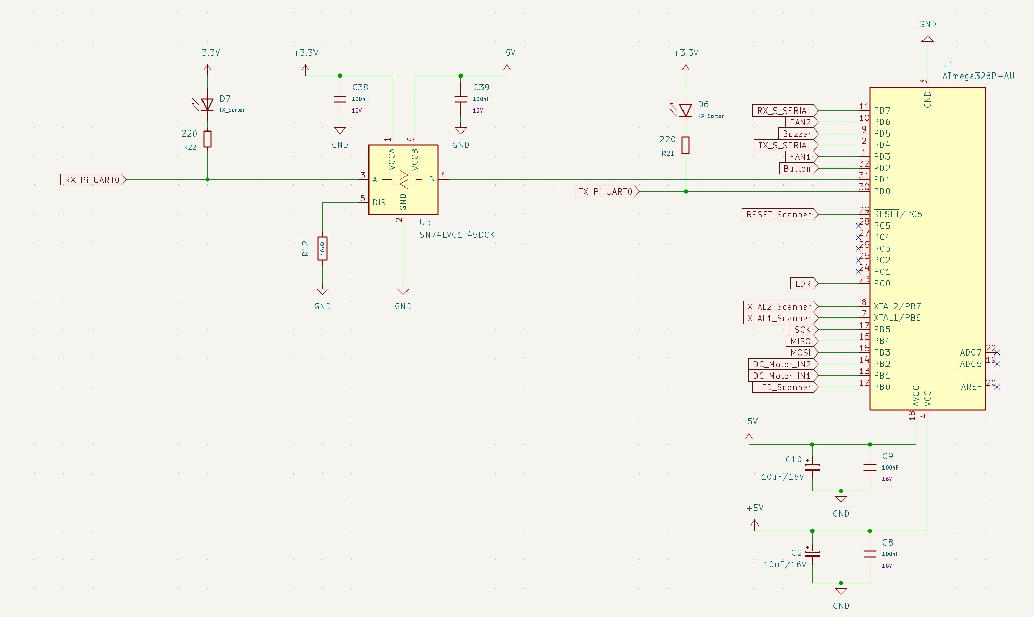
Schaltplan mit ATmega32PB Mikrocontroller
+3.3V, C38 100nF 16V, GND, VCCA, VCCB, U5 SN74LVC1T45DCK, A, B, DIR, R1.2 100, R21 220, D6 RX_S_SERIAL, RX_S_SERIAL, FAN2, Buzzer, TX_S_SERIAL, FAN1, Button, U1 ATmega32PB-AU, PD7, PD6, PD5, PD4, PD3, PD2, PD1, PD0, RESET
in „Auswahl Bulk Kondesatoren“ · Platinen · · Schaltpläne
-
Datei
initusart.c
: Deltec Automtive GmbH&Co.KG Version : 1.1 Datum : 2010-03-12 Autor : Sperl Andreas Chip Type : ATMEGA32 Clock Frequenz : 14 745 600 Hz ************************************************************************************************************************************************** USART oder UART initialisieren
in „usart umschalten“ · Mikrocontroller und Digitale Elektronik ·
-
Datei
incap.c
/* Input capture Beispiel, für einen Atmega48 Autor: J.Gerlach Idee: aus dem mikrocontroller.net forum */ #include <avr/io.h> #include <avr/interrupt.h> #include <inttypes.h> // globals volatile uint16_t dif; int main(void) { DDRD =0x00; /*
in „Input Capture Flag Atmega16“ · Mikrocontroller und Digitale Elektronik ·
-
Datei
adc.h
/*####################################################################################### ATmega8,16,32,64 and 128 ADC Functions Copyright (C) 2005 Branko Golubovic branko.golubovic@gmx.at #######################################################################################*/ #ifndef _ADC_H
in „ATmega32 ADC differentiell“ · Mikrocontroller und Digitale Elektronik ·
-
Datei
adc.h
/*####################################################################################### ATmega8,16,32,64 and 128 ADC Functions Copyright (C) 2005 Branko Golubovic branko.golubovic@gmx.at #######################################################################################*/ #ifndef _ADC_H
in „Win AVR adc ansprechen“ · Mikrocontroller und Digitale Elektronik ·
-
Datei
lcd.S.txt
der Bits sbrc r17, 0x03 ori r16, 0x04 sbrc r17, 0x02 ori r16, 0x08 sbrc r17, 0x01 ori r16, 0x10 sbrc r17, 0x00 ori r16, 0x20 // Und PORTD zurückschreiben sts 0x2B, r16 // Tatsächlich senden call sendcommand // Und zurück ret // Lässt
in „LCD-Display funktioniert nur nach Übertragung des Programms“ · Mikrocontroller und Digitale Elektronik ·
-
Datei
Buffer.c
variables: volatile uint8_t TMR1COMPA_flag = 0; //Timer 1 Compare Match-Flag (ISR sets Flag) volatile uint16_t tcounter = 0; //"Uhr" //Der Komplette Buffer (Indizes und Data (struct)) volatile uint8_t index_read = 0; //Buffer read index volatile uint8_t index_write = 0; //Buffer write index volatile struct { unsigned time:16; //16 Bit für time unsigned x_axis:1; // 1 Bit x_axis unsigned x_dir:1; // 1 Bit für x_dir usw... unsigned y_axis:1; unsigned y_dir:1; unsigned z_axis:1; unsigned z_dir:1; unsigned sensor_answer:1; /
in „Interrupt Fehlerquellen - FIFO Buffer“ · Mikrocontroller und Digitale Elektronik ·
-
Datei
forum_code.c
SommerSemester 2013 Uhr an LCD mit Weckfunktion & Datum Alarm.c AVR Studio 4 Compiler Options auf "0s" AVR Atmega32 */ #include <avr/io.h> #include <util/delay.h> #include "lcd.h" /*Name leapyeartester Eingabeparameter uint8_t year (Eingestelltes Jahr im Hauptprogramm) Rückgabeparameter uint16_t 1 , wenn Schaltjahr
in „AVR - if/while werden übersprungen“ · Mikrocontroller und Digitale Elektronik ·
-
PDF
schaltplan-final.pdf
5 4 3 2 1 J1 Servo1 J2 Servo2 VCC IC3A VCC Q1 14 Q16 MHz VCC L1 SW1 R1 1 2 3 1 2 3 C2 2 1 KHT1 10k 100µH C1 74HC14 7 RESET POW4 VCC 22pF 22pF PWM2 C3 1 3 PWM0 100nF IC1 C4 IC3B 32 C C 12 100nF RESET AREF V V XTAL2 J7 4 3 J6 9 RESET A XTAL1 13 D ST2 1 SCHRANKE
in „LCD DEM20485 in gerade Zeile springen (c't-Bot)“ · Mikrocontroller und Digitale Elektronik ·
-
Datei
LCD_Programm.txt
sendet ein Datenbyte an das LCD void lcd_data(unsigned char temp1) { unsigned char temp2 = temp1; 16. LCD_PORT |= (1<<LCD_RS); // RS auf 1 setzen 17. temp1 = temp1 >> 4; 18. temp1 = temp1 & 0x0F; 19. LCD_PORT &= 0xF0; 20. LCD_PORT |= temp1; // setzen 21. lcd_enable(); 22. temp2 = temp2 & 0x0F; 23. LCD_PORT
in „LCD-Tutorial: einige zeilen sind unverständlich“ · Mikrocontroller und Digitale Elektronik ·
-
Datei
tasten_matrix.c
// tasten_matrix.c // for NerdKits with ATmega168 //Verbindung Tastenfeld - ATmega168 // 1 PC1 // 2 PC2 // 3 PC3 // 4 PB2 // 5 PB3 // 6 PB4 // 7 PB5 //Taste verbindet PBx mit PCy // 1 2 1 // 2 2 2 // 3 2 3 // 4 3 1 // 5 3 2 // 6 3 3 // 7 4 1 //
in „Tastenmatrix 3x4 Problem“ · Mikrocontroller und Digitale Elektronik ·
-
PDF
PFC_FBC.pdf
Aufbereitung der Netzspannung für die Messung N _ T _ 3 3 + 3 IC16C 0 T LM324(SO14) 1 A D B L_SENSE 10 D18 8 R20 30k L_POLARITY 9 N BAT43 N R21 10k N L O T _ 3. 01 3 N + 91 _ R T IC16B 4 _ N LM324(SO14) T V 9 A 1 5 D B + L_SENSE R17 10k 7 L_VALUE R R16 20k 6 k IC16A
in „PFC + Vollbrücken-Gegentaktwandler“ · Analoge Elektronik und Schaltungstechnik ·
-
PDF
4-Gewinnt-Schaltung.pdf
XLAT OUT6 LED_7 OUT7 14 OUT7 14 OUT7 14 LED_8 15 LED_40 15 LED_72 15 OUT8 LED_41 OUT8 LED_73 23 OUT8 16 LED_9 23 XERR OUT9 16 LED_42 23 XERR OUT9 16 LED_74 XERR OUT9 LED_10 17 17 OUT10 17 OUT10 LED_43 OUT10 LED_75 18 LED_11 OUT11 18 LED_44 OUT11 18 LED_76 OUT11 LED_12 19 19 OUT12 19 LED_13 4 OUT12 20 LED
in „TLC5940 (6x kaskadiert) – LED blinkt nur kurz beim Einschalten, danach keine Funktion“ · Mikrocontroller und Digitale Elektronik ·
-
Datei
t6963c.txt
#define DDR(x) (*(&x - 1)) /* address of data direction register of port x */ #if defined(__AVR_ATmega64__) || defined(__AVR_ATmega128__) /* on ATmega64/128 PINF is on port 0x00 and not 0x60 */ #define PIN(x) ( &PORTF==&(x) ? _SFR_IO8(0x00) : (*(&x - 2)) ) #else #define PIN(x) (*(&x - 2)) /* address
in „Halbkreisformel verstehe ich nicht!“ · Mikrocontroller und Digitale Elektronik ·
-
Datei
t6963c.h
#define DDR(x) (*(&x - 1)) /* address of data direction register of port x */ #if defined(__AVR_ATmega64__) || defined(__AVR_ATmega128__) /* on ATmega64/128 PINF is on port 0x00 and not 0x60 */ #define PIN(x) ( &PORTF==&(x) ? _SFR_IO8(0x00) : (*(&x - 2)) ) #else #define PIN(x) (*(&x - 2)) /* address
-
Datei
lcd.c
******* Title : HD44780U LCD library Author: Thomas Finn File: $Id: lcd.c,v 1.14.2.1 2006/01/29 12:16:41 $ Software: AVR-GCC 4.1.2 Target: any AVR device, memory mapped mode only for AT90S4414/8515/Mega DESCRIPTION Basic routines for interfacing a HD44780U-based text lcd display Originally based on Peter
in „Display Programmierung mit GCC 16x4 Display“ · Mikrocontroller und Digitale Elektronik ·
-
Datei
adc.c
fleury Date: December 2003 Software: AVR-GCC 3.3 Hardware: Any AVR with built-in ADC, tested with ATmega8 at 1Mhz Description: An analog signal applied to analog input ADC0 is converted into a 10 bit digital value using the built-in Analog-to-digital Converter. The higher 8 bits of the converted value
in „analogen Ports beim Mege 8 und Mega 16“ · Mikrocontroller und Digitale Elektronik ·
-
Datei
adc.c
fleury Date: December 2003 Software: AVR-GCC 3.3 Hardware: Any AVR with built-in ADC, tested with ATmega8 at 1Mhz Description: An analog signal applied to analog input ADC0 is converted into a 10 bit digital value using the built-in Analog-to-digital Converter. The higher 8 bits of the converted value
-
PDF
N2080.pdf
line 10 DB3 Data bus line 11 DB4 Data bus line 12 DB5 Data bus line LCD-Punktmatrixmodul YL162-90 16x 2 Zeichen mit LED-Hintergrundbeleuch- DB6 Data bus line tung, kompatibel zum bekannten Controller HD44780., 8-bit-/ 4-bit 14s mode, DB7 Data bus line getestetmitAVR-ATMEGA32. 15 A LED B/L (+) TechnischeDaten: !Betriebsspannung: +5V !KontrastspannungVo: -2,5V ! Anzeigefläche60x16mm ! Maße (BxHxT): 84x44x11 mm Pos.N2080
in „HD44780 LCD - Keine Anzeige“ · Mikrocontroller und Digitale Elektronik ·
-
Datei
main.c
***********************************************************/ /* definition for EEPROM memory for ATMega(16-128) and newer*/ /****************************************************************************/ uint8_t out = 0; /****************************************************************************/ /*
in „XMega und timer interrupt“ · Mikrocontroller und Digitale Elektronik ·
-
Datei
w2313.c
man auch nachtrtäglich beim Kompileraufruf angeben. avr-gcc blinky.c -c -o blinky.o -Os -g -mmcu=atmega8 -DF_CPU=1000000 */ #include <avr/io.h> #include <util/delay.h> #include <stdint.h> //Prototypen void sleep_ms(uint16_t ms); //LED Defines #define LED_DDR DDRB #define LED_PORT PORTB #define LED_PORTPIN
in „AVR GCC, at90s2313, Atmega8, wie kompiliere ich richtig?“ · Mikrocontroller und Digitale Elektronik ·
-
PDF
YL162_90.pdf
line 10 DB3 Data bus line 11 DB4 Data bus line 12 DB5 Data bus line LCD-Punktmatrixmodul YL162-90 16x 2 Zeichen mit LED-Hintergrundbeleuch- DB6 Data bus line tung, kompatibel zum bekannten Controller HD44780., 8-bit-/ 4-bit 14s mode, DB7 Data bus line getestetmitAVR-ATMEGA32. 15 A LED B/L (+) TechnischeDaten: !Betriebsspannung: +5V !KontrastspannungVo: -2,5V ! Anzeigefläche60x16mm ! Maße (BxHxT): 84x44x11 mm Pos.N2080
in „LCD - ich verzweifele“ · Mikrocontroller und Digitale Elektronik ·
-
Datei
0x00.asm
.include "m8def.inc" ;ATMega8 Include-Datei .equ CLOCK = 4000000 .equ BAUD = 19200 .equ UBRRVAL = CLOCK/(BAUD*16)-1 .def temp = r16 ;Speicherpointer xl(r26) xh(r27) ldi xh,0x00 ;0x0068 weil 8(32 später) für Einstellungen ldi xl
in „0x00 über UART übertragen“ · Mikrocontroller und Digitale Elektronik ·
-
 Bild
Bild
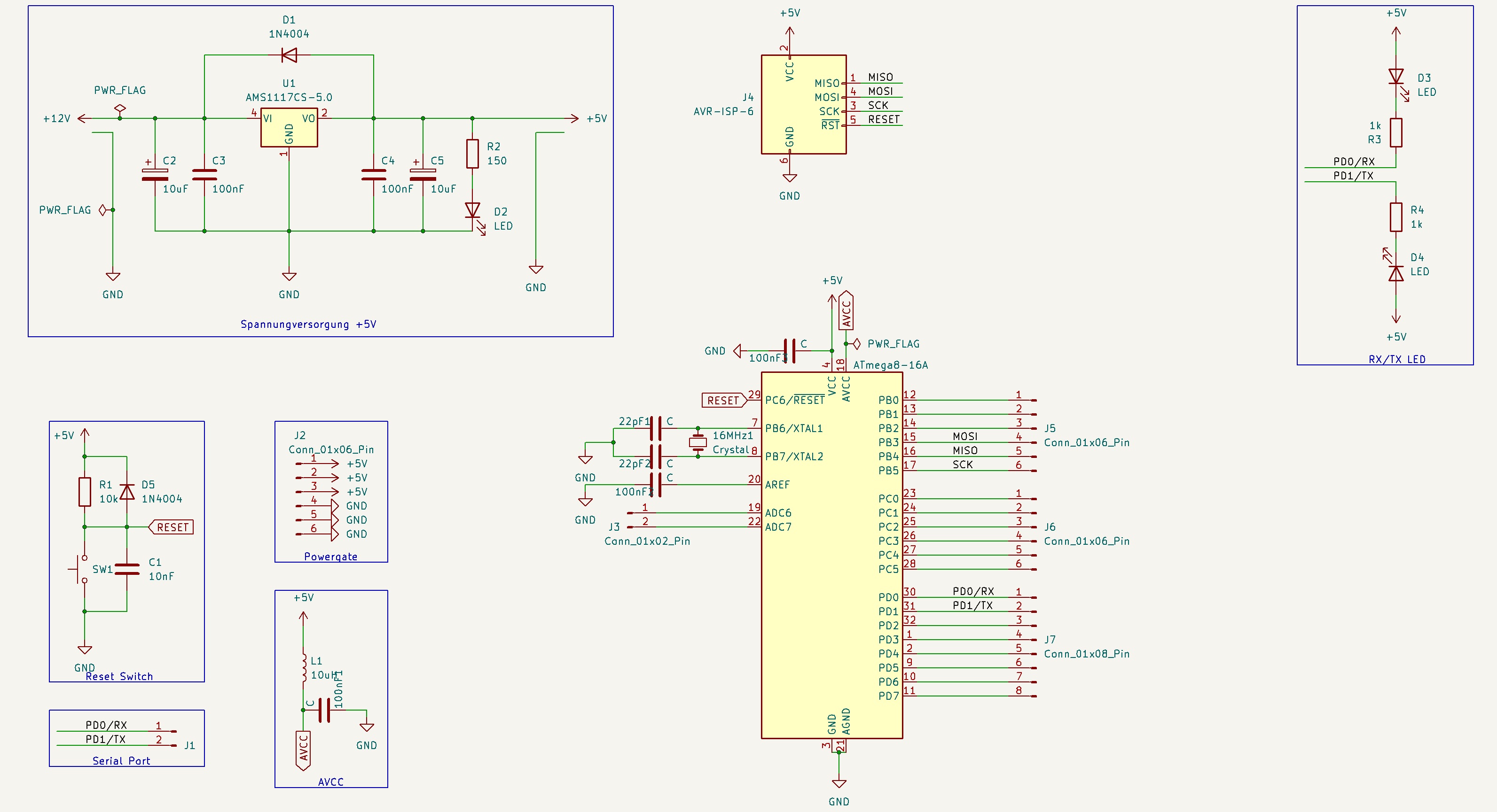
Schaltplan eines ATmega8 Mikrocontroller-Projekts
_01x06_Pin, R1 10k, 1N4004, RESET, SW1, C1 10nF, GND, Powergate, +5V, L1 10uF, 100nF, AVCC, GND, ATmega8-16A, 16MHz Crystal, PC6/RESET, PB7/XTAL2, PB6/XTAL1, AREF, ADC7, ADC6, PC0 bis PC7, PD0 bis PD7, J5 Conn_01x06_Pin, J6 Conn_01x06_Pin, J7 Conn_01x08_Pin
in „Wiedereinsteiger Atmega-8 Schaltung“ · Mikrocontroller und Digitale Elektronik · · Schaltpläne
-
PDF
SCHALTPLAN_DCF77_1WIRE_SPARVARIANTE.pdf
4 3 2 1 0 ) ) ) ) ) ) ) ) a C C C C C C N FE C B B B B B r ( ( ( ( ( ( G R V ( ( ( ( ( m ( ( ( r ATmega8-16 r ) ) ) ) ) ) ) D ) 7 5 6 7 0 2 C D D D D D C3 4 C N B B D D D B P ( ( ( ( ( ( ( ( P( ( ( ( ( ( 1 1 2 3 4 5 6 7 8 9 1 1 1 1 1 100nF 16MHz Reset 4 4 4 22pF*22pF* 1-WIRE 08/2012 Version 1
in „DCF / DCF77 UHR 1-WIRE / 1WIRE SLAVES / DEVICES ATmega8 ASSEMBLER“ · Projekte & Code ·
-
PDF
SCHALTPLAN_DCF_TWI.pdf
p 5 4 3 2 1 0 D F C 5 4 3 2 1 A P CPC P C P P P N R VC P P P P P i ( ( ( ( ( ( ( ( ( ( ( ( ( ( m ATmega8-16 o ) ) ) ) ) ) ) ) ) ) ) ) ) ) - 6 0 1 2 3 4 C N 6 B D D D B 0 I P DPD P D P CP P V G PB ( ( ( ( ( P , 1 2 3 4 5 6 7 8 9 1 1 1 1 1 1 100nF 16MHz 22pF*22pF* Reset L1 DCF77 L wichtig, da Spannung
in „DCF77 als SLAVE TWI I2C Assembler ATmega8“ · Projekte & Code ·
-
Datei
USART.c
4000000" #define F_CPU 4000000UL #endif #define BAUD 9600UL #define UBRR_VAL ((F_CPU+BAUD*8)/(BAUD*16)-1) #define BAUD_REAL (F_CPU/(16*(UBRR_VAL+1))) #define BAUD_ERROR ((BAUD_REAL*1000)/BAUD) #if ((BAUD_ERROR<990)||(BAUD_ERROR>1010)) #error Systematische Fehler der BAudrate groesser 1% und damit zu hoch! #endif /* UART_init Bsp. ATMega8*/ void uart_init(void) { UBRRH = UBRR_VAL >> 8 ; UBRRL = UBRR_VAL & 0xFF; UCSRB |= (1<<TXEN); UCSRC = (1<<URSEL)|(1<<UCSZ1)|(1<<UCSZ0); } void inittimer() { //32768 1/s mit 8Bit 2^8 -> 256s mit Prescaler
in „ATMega8 USART“ · Mikrocontroller und Digitale Elektronik ·
-
PDF
SCHALTUNG_PLL_TESTER.pdf
) ) ) ) 5 4 3 2 1 0 D F C 5 4 3 2 1 P CPC P C P P P N R VC P P P P P ( ( ( ( ( ( ( ( ( ( ( ( ( ( ATmega8-16 ) ) ) ) ) ) ) ) ) ) 5 6 7 ) C D D D D D C3 4 C N B B D D D B 0 P P P P P P V G P ( ( ( ( ( 1, 1 2 3 4 5 6 7 8 9 1 1 1 1 1 R1 100nF 0 0 0 4 R 4 R 4 R C1 C2 C3 22 22 16MHz
in „4046 / 74HC4046 / 74HCT4046 / PLL Beispiele“ · Mikrocontroller und Digitale Elektronik ·
-
Datei
main.c
- Compiler : IAR EWAAVR 2.28a/3.10c * * - Support mail : avr@atmel.com * * - Supported devices : ATmega48/88/168 * * - AppNote : AVR444 - Sensorless control of three-phase brushless * DC motors with ATmega48. * * - Description : Example of how to use the ATmega48 for sensorless * control of a three phase
in „Funktionen vs Interrupts“ · Mikrocontroller und Digitale Elektronik ·
-
Datei
AVR-Studio2.txt
avrgcc\avr\include" -I"C:\Dokumente und Einstellungen\Root\Desktop\test-akkuboost\akku-test\." -mmcu=atmega32 -Wall -gdwarf-2 -std=gnu99 -DF_CPU=8000000UL -Os -funsigned-char -funsigned-bitfields -fpack-struct -fshort-enums -MD -MP -MT akkuboost2.o -MF dep/akkuboost2.o.d -c ../akkuboost2.c In file included
in „Suche Hilfe beim Compilieren von fertigem C-Code“ · Mikrocontroller und Digitale Elektronik ·
-
Datei
iom16.h
OUT OF THE USE OF THIS SOFTWARE, EVEN IF ADVISED OF THE POSSIBILITY OF SUCH DAMAGE. */ /* $Id: iom16.h,v 1.4 2003/01/08 11:14:10 joerg_wunsch Exp $ */ /* avr/iom16.h - definitions for ATmega16 */ #ifndef _AVR_IOM16_H_ #define _AVR_IOM16_H_ 1 /* This file should only be included from <avr/io.h>, never
-
Datei
rs232.asm
AVR: 4 MHz # ;# # ;# CS-SOFT # ;########################################### .include "m8def.inc" ;Atmega8 ;.include "2313def.inc" ; Viele definierte Register werden nicht gebraucht .DEF rd1l = R0 ; LSB Divident Multiplikator 1 (8 Bit) .DEF rd1h = R1 ; LSB Divident Multiplikator 1 (8 Bit) .DEF rd2l = R2
in „AVR4Studio hat nen Bug?“ · Mikrocontroller und Digitale Elektronik ·
-
Datei
uart.asm
AVR: 4 MHz # ;# # ;# CS-SOFT # ;########################################### .include "m8def.inc" ;Atmega8 ;.include "2313def.inc" ; Viele definierte Register werden nicht gebraucht .DEF rd1lh = R0 ; LSB Divident Multiplikator 1 (8 Bit) .DEF rd1l = R1 ; LSB Divident Multiplikator 1 (8 Bit) .DEF rd1h =
in „Fuse Frage zu Atmega8“ · Mikrocontroller und Digitale Elektronik ·
-
Datei
uart.asm
AVR: 4 MHz # ;# # ;# CS-SOFT # ;########################################### .include "m8def.inc" ;Atmega8 ;.include "2313def.inc" ; Viele definierte Register werden nicht gebraucht .DEF rd1lh = R0 ; LSB Divident Multiplikator 1 (8 Bit) .DEF rd1l = R1 ; LSB Divident Multiplikator 1 (8 Bit) .DEF rd1h =
-
PDF
Hauptplatine.pdf
PIU309 R2OUT R2IN PIU308 COC9 PIP3033 C 22pF Y1Y PI13012XTAL2 GND PI11031 100nF GND 15 6 9 RS232 C 16MHz PIU1013XTAL1 GND PIU1011 PIU3015GND VEE PIU306 PIC902 PIC901 C5 Y0 Cap Pol1 PIC501 PIC502 GND COP132ACPE 10uF GND Cap ATmega16-16PC VCC P12 22pF PIP12011 PIP12022 Summer VCC P131 GND CSPIP13011 2
in „AVR Wecker mit Netzwerk“ · Mikrocontroller und Digitale Elektronik ·
-
Datei
TLC_5940_Demystifying.c
define outputState(port, pin) ((port) & (1 << (pin))) #if (12 * TLC5940_N > 255) #define dcData_t uint16_t #else #define dcData_t uint8_t #endif #if (24 * TLC5940_N > 255) #define gsData_t uint16_t #else #define gsData_t uint8_t #endif #define dcDataSize ((dcData_t)12 * TLC5940_N) #define gsDataSize ((gsData_t
in „TLC5940 am ATmega16“ · Mikrocontroller und Digitale Elektronik ·
-
Datei
main.c
/* * * Created: 26.08.2021 12:01:13 * Author : Joachim J. * MC: ATmega 328p mit 16MHz / Arduino Nano */ #include <avr/io.h> #include <avr/interrupt.h> #include <util/delay.h> #include <stdio.h> #include <stdlib.h> #include <util/atomic.h> /*-------- Define --------*/ #define FOSC 16000000 //Clock Speed #define BAUD 19200 //Debug #define MYUBRR FOSC/16/BAUD-1 #define LED_PIN PC0 #define LED_ON PORTC |= (1 << LED_PIN) #define LED_OFF PORTC &= ~(1 << LED_PIN) #define set_cap_low_high TCCR1B |= (1 << ICES1); //Bit setzen: Capture von low zu high / rising
in „Servo-Pulssignalläge messen mit Atmega328p“ · Mikrocontroller und Digitale Elektronik ·
-
PDF
_Schaltplan.pdf
0u1 PC5 24 PC4 23 GND GND GND GND GND 22 PC3 21 GND PC2 20 VCC (SDA)PC1 19 C R4 (SCL)PC0 R7 1k5 X8 C 16 TCK 1 2 GND V 1k5 (OC2)PD7 15 3 4 (ICP)PD6 TDO VCC V1 (OC1A)PD5 14 TMS 5 6 RST BC807 (OC1B)PD4 13 VDC 7 8 (INT1)PD3 12 S3 TDI 9 10GND (INT0)PD2 11 R16 2 8 3 8 (TXD)PD1 10 3 1 JTAG R 6 R 6 (RXD)PD0 9 4 2 3k3 GND S2 8xLED red ATMEGA16-16AU A 3 1 R17 V8 R26 N 0 V2 4 2 G 1 IR-LED S1 3k3 1k5 V9 R27 D R5 3 1 R18 N GND 4 2 1k5 G 1k5 3k3 V10 R28 D V3 VCC S0 N R19 1k5 G VCC VCC R6 3 1 V11 R29 D OUT OUT 4 2 3k3 N GND GND 1k5 1k5 G C9
in „SI4713 über SPI mit einem Atmega“ · Mikrocontroller und Digitale Elektronik ·
-
Datei
Fmeter_GPS.c
/* Beispielprogramm 'reziproker Frequenzzaehler' mit GPS-Signal stabilisiert fuer ATmega162 und AVR-GCC. Funktionsbereich etwa 0,004Hz - 250kHz bei 16MHz Prozessortakt Neben der üblichen Frequenzmessung an ICP1 wird zusätzlich über ICP3 die interne Taktfrequenz anhand eines 1pps GPS-Signals
in „reziproker Frequenzzähler, GPS-stabilisiert, ATmega162“ · Projekte & Code ·
-
Datei
RFM01_RX.asm
**************************************** ; todays project: ; control The RFM01 RX Module with an ATMega 48/168/328 ; Receive an FSK data stream with it ; constants @ 16 Mhz clk ; ****************************************************************** ; crystal osc. frequency .equ F_CPU = 16000000 ; this is
in „Problem mit RFM01/RFM02“ · Mikrocontroller und Digitale Elektronik ·
-
Datei
RFM01_RX.asm
**************************************** ; todays project: ; control The RFM01 RX Module with an ATMega 48/168/328 ; Receive an FSK data stream with it ; constants @ 16 Mhz clk ; ****************************************************************** ; crystal osc. frequency .equ F_CPU = 16000000 ; this is
in „RF01 und RF02 433 MHz Funkmodul“ · Mikrocontroller und Digitale Elektronik ·