-
PDF
datasheet.pdf
ms 750 A 2 T vj 150 °C, 10 ms 600 2 i t T vj25 °C, 8,3...10 ms 2800 A s T vj150 °C, 8,3...10 ms 1800 A s VF T vj= 25 °C; F = 150 A 1,6 V V(TO) T vj= 150 °C 0,85 V T T vj= 150 °C 8 m RD T vj= 25 °C; VRD = VRRM 1 mA SKB SKD T vj= 150 °C; RD = VRRM 10 mA t T = 25 °C typ. 10 s rr vj G 2000 Hz Rthjc total 0,65 0,45 °C/W Features Rthch total 0,06 0,06 °C/W • Isolated metal case with screw R T = 35 °C; P1A/120 F 0,9 0,7 °C/W terminals thja
in „[V oder T] TDS420“ · Markt ·
-
PDF
SKD50-08_A3_Gleichrichtermodul_Datasheet.pdf
ms 750 A 2 T vj 150 °C, 10 ms 600 2 i t T vj25 °C, 8,3...10 ms 2800 A s T vj150 °C, 8,3...10 ms 1800 A s VF T vj= 25 °C; F = 150 A 1,6 V V(TO) T vj= 150 °C 0,85 V T T vj= 150 °C 8 m RD T vj= 25 °C; VRD = VRRM 1 mA SKB SKD T vj= 150 °C; RD = VRRM 10 mA t T = 25 °C typ. 10 s rr vj G 2000 Hz Rthjc total 0,65 0,45 °C/W Features Rthch total 0,06 0,06 °C/W • Isolated metal case with screw R T = 35 °C; P1A/120 F 0,9 0,7 °C/W terminals thja
-
Datei
bauteile_002.txt
----------------------------------------------------------------- 500 S1M/11T SMD Vishay 100 4,00 2000 100nF/X7R 0603 100 1,00 Keramik-C 200 B140-7 Liteon 50 1,00 Shottky-Diode 400 LSGT677K SMD Osram 50 2,50 TOPLED 200 BAT54A SOT23 Fairchild 100 2,00 200 BAT54S SOT23 Fairchild 100 2,00 200 BAT54C SOT23
in „Verkaufe diverse Bauteile“ · Markt ·
-
PDF
Magic_switch.pdf
161 01 Mastereinheit: HV 3000 mm NV 2000 mm Schaltleitung: HV 150 mm n NV 300 mm c Zubehör Standby: <0,5 W - Mastereinheit e inklusive Sensoren at Mastereinheit 12 Volt DC – 36 W 30 142 01 c S Mastereinheit 12 Volt DC – 60 W incl. EVG 30 146
in „Hilfe bei Elektrotechnik im Schreiner-Meisterstück“ · Analoge Elektronik und Schaltungstechnik ·
-
PDF
2_20.pdf
during 40µs data write and read. Display On/Off Sets ON/OFF of all display (D) cursor 0 0 0 0 0 0 1 D C B ON/OFF (C), and blink of cursor positi40µs Control character (B). Cursor / Display 0 0 0 0 0 1 S/C R/L * * Moves the Cursor and shifts the displa40µs Shift without changing DD RAM contents. Sets interface
in „Brauche Hilfe beim Schaltplan eines LCDs“ · Mikrocontroller und Digitale Elektronik ·
-
PDF
DMX_512.PDF
plate marking 25 5 Pin XLR - Cable Scheme Permitted Marking at Comments 26 Pins Wired XLR 27 1, 2, 3 C1 DMX512 Scheme C1 28 1, 2, 3 C2 DMX512 Scheme C1 Can be upgraded to full wiring of XLR and remarked for Scheme C2 at later date if required 29 1, 2, 3, 4, 5 C1 not permitted -Note 1- 30 1, 2, 3, 4, 5 C2 DMX512 Scheme C2 necessary for use with TYPE 2 – TYPE 5 ports 31 a(1, 2, 3) b(1, 2, 3) C5.1 DMX512 Scheme C1 One CAT 5 Cable w/ two universes 32 1, 2, 3 C5.2 DMX512 Scheme C1 Can be upgraded to full
in „DMX Kabel anschließen“ · Mikrocontroller und Digitale Elektronik ·
-
PDF
DMX_512.PDF
plate marking 25 5 Pin XLR - Cable Scheme Permitted Marking at Comments 26 Pins Wired XLR 27 1, 2, 3 C1 DMX512 Scheme C1 28 1, 2, 3 C2 DMX512 Scheme C1 Can be upgraded to full wiring of XLR and remarked for Scheme C2 at later date if required 29 1, 2, 3, 4, 5 C1 not permitted -Note 1- 30 1, 2, 3, 4, 5 C2 DMX512 Scheme C2 necessary for use with TYPE 2 – TYPE 5 ports 31 a(1, 2, 3) b(1, 2, 3) C5.1 DMX512 Scheme C1 One CAT 5 Cable w/ two universes 32 1, 2, 3 C5.2 DMX512 Scheme C1 Can be upgraded to full
in „DMX 512 Lichtsteuerpult bauen“ · Mikrocontroller und Digitale Elektronik ·
-
Datei
Boardtester.bas
'-------------------------------------------------------------- ' (c) 1999-2000 MCS Electronics '-------------------------------------------------------------- ' file: PORT.BAS ' demo: PortB and PortD '-------------------------------------------------------------- $regfile
in „NEED HELP bin wohl zu dumm“ · Mikrocontroller und Digitale Elektronik ·
-
PDF
CZX3500.pdf
Contact Arrangement ....................SPDT.... Operational Temperature ....................- 25°C to + 50°C Max Temperature Rise ....................20°C.... Weight ....................Approx. 320 g Mounting ....................Four screws Cable Connections ....................3 N type female connectors
in „Koaxialrelais im Gehäuse betreiben“ · HF, Funk und Felder ·
-
PDF
EZPack_XL__2260mAh.pdf
Current: 1080mA Rec. Charge Cut Off: by current 50mA or timer 4h Max. Continuous Discharge Current: 2000mA Rec. Discharge Cut Off: 3V Internal Impedance: approx. 110mΩ Exp. Cycle Life: >500 cycles >70% of initial cap. (0.5C/0.5C) Cell Protection Overcharge Detection: 4.3 ± 0.02V (0.8 to 1.2sec. delay,
in „Li-Ion Akku Lade-IC gesucht“ · Mikrocontroller und Digitale Elektronik ·
-
PDF
FPF2700.pdf
Human Body Model, JESD22-A114 2000 V w Protection Level Charged Device Model, JESD22-C101 2000 e (1) ™ Thermal Resistance, MLP 3x3 , See Figure 8 80 °C/W JA Junction to Ambient SO8 , See Figure 10 102 . ~ Note: 2 1. Thermal resistanceJAθ
in „Highside-Switch gesucht“ · Analoge Elektronik und Schaltungstechnik ·
-
PDF
ANNE-50X_.pdf
Termination SMA ANNE-50X+ 50Ω DC to 20000 MHz Maximum Ratings Features Operating Temperature -55°C to 100°C • wideband coverage, DC to 20000 MHz CASE STYLE: LL561 Storage Temperature -55°C to 100°C • return loss, 40 dB typ. up to 4000 MHz Permanent damagemay occur if any of theselimits areexceeded
in „Abschlusswiderstand zur Vermessung“ · HF, Funk und Felder ·
-
 Bild
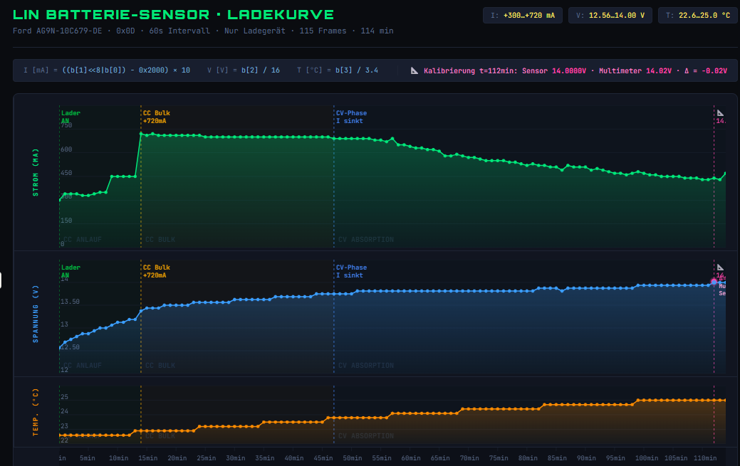
Diagramm einer Ladekurve eines Batterie-Sensors
LIN BATTERIE-SENSOR · LADEKURVE I: +388..+728 mA V: 12.56..14.80 V T: 22.6..25.0 °C Ford AG9N-10C679-DE - 0x8D - 60s Intervall - Nur Ladegeraet - 115 Frames - 114 min I [mA] = ((b[1]<<8|b[0]) - 0x2000) * 10 V [V] = b[2] / 16 T [°C] = b[3] / 3.4 Lader AN CC Bulk CV-Phase I sinkt CC ANLAUF CC BULK CV ABSORPTION STROM (mA) 600 450 150 0 SPANNUNG (V) 14 13.50 13 12.50 12 TEMP. (°C) 25 24 23 22 5min 10min 15min 20min 25min 30min 35min 40min 45min 50min 55min 60min 65min 70min 75min 80min 85min 90min 95min 100min 105min 11min
in „Reverse Engineering eines LIN Bus“ · Mikrocontroller und Digitale Elektronik · · Screenshots
-
PDF
EntwurfV3.pdf
überprüfen IC104-A IC107-A 1 2 P2_ACTIVE R107 1*2 4 5 100k B 4 0k S Q 8 Y 15 +5V_1+ 4 n 3 74HC14-PW 1 1 6 C R IC105-A P2_ACTIVE 2 D 1 7 1 M C 74LVC1G58-GW C 4 R 1 1 4 SEL_TRG 3 B Y CP IC2-B GND P 1 6 3 9 74LVC1G97-GW R Q EN_P1/EN_P2 3 4 T101 1 1 1 +5V_2 GND GND S C 74HC74-PW B 74HC14-PW GND GND +5V 2000 ms
in „Einfache USB Upstream Port Umschaltung“ · Mikrocontroller und Digitale Elektronik ·
-
PDF
dts_vtb8440bh-8441bh.pdf
ABSOLUTE MAXIMUM RATINGS Planar silicon photodiode in recessed ceramic StorageTemperature: -20°Cto75°C package. The package incorporates an infrared OperatingTemperature: -20°Cto75°C rejection filter. These diodes have very high shuntresistanceandhavegoodblueresponse. ELECTRO-OPTICAL CHARACTERISTICS @
in „Kurze Frage zu Transimpedanzverstärker - Single Supply möglich (für Photodiode)“ · Analoge Elektronik und Schaltungstechnik ·
-
PDF
830055299.pdf
number 13 Frequency Parameters Frequency 25.0MHz Frequency Tolerance ±20.00ppm Tolerance Condition @25°C Frequency Stability ±30.00ppm Operating Temperature Range -40.00 to 85.00°C Overtone Order Fundamental Ageing ±5ppm max per year @25°C Electrical Parameters Outline (mm) Load Capacitance (CL) 18.00pF
in „Schaltung W5500“ · Mikrocontroller und Digitale Elektronik ·
-
Datei
fat16.c
/** Calc Sector from given Cluster @param Cluster @return Sector */ static u32 cluster2sector(u16 c) { c -= 2; if (cluster_size == 1) {} else if (cluster_size == 2) c = c<<1; else if (cluster_size == 4) c = c<<2; else if (cluster_size == 8) c = c<<3; else if (cluster_size == 16) c = c<<4; else if (cluster_size == 32) c = c<<5; else if (cluster_size == 64) c = c<<6; else if (cluster_size == 128) c = c<<7; return c + file_pos; } /** Read Long File Name Reads data from sharedmem Stores result in global struct fat_filedata.name
in „[atmega8] UART-Daten auf SD-Karte schreiben“ · Mikrocontroller und Digitale Elektronik ·
-
PDF
504925-panasonic-aqz202-photomos-relais-1-st-1-schliesser-60-vdc-60-vac-3000-ma-polzahl-4.pdf
power dissipation PT 1.6 W I/O isolation voltage V iso 2,500 V AC Temperature Operating T opr –40°C to +85°C –40°F to +185°F Non-condensing at low temperatures limits Storage Tstg –40°C to +100°C –40°F to +212°F 2) Electrical characteristics (Ambient temperature: 25°C 77°F) Item Symbol AQZ202 AQZ205
in „Suche Halbleiterelement als Ersatz für Relai in Radar-Bewegungsmelder“ · Analoge Elektronik und Schaltungstechnik ·
-
PDF
504925-panasonic-aqz202-photomos-relais-1-st-1-schliesser-60-vdc-60-vac-3000-ma-polzahl-4.pdf
power dissipation PT 1.6 W I/O isolation voltage V iso 2,500 V AC Temperature Operating T opr –40°C to +85°C –40°F to +185°F Non-condensing at low temperatures limits Storage Tstg –40°C to +100°C –40°F to +212°F 2) Electrical characteristics (Ambient temperature: 25°C 77°F) Item Symbol AQZ202 AQZ205
in „Welche Eigenschaften haben Solid State Relais, SSR ?“ · Offtopic ·
-
PDF
504925-panasonic-aqz202-photomos-relais-1-st-1-schliesser-60-vdc-60-vac-3000-ma-polzahl-4.pdf
power dissipation PT 1.6 W I/O isolation voltage V iso 2,500 V AC Temperature Operating T opr –40°C to +85°C –40°F to +185°F Non-condensing at low temperatures limits Storage Tstg –40°C to +100°C –40°F to +212°F 2) Electrical characteristics (Ambient temperature: 25°C 77°F) Item Symbol AQZ202 AQZ205
in „Kann diese Schaltung den 74HC132 killen?“ · Analoge Elektronik und Schaltungstechnik ·
-
PDF
504925-panasonic-aqz202-photomos-relais-1-st-1-schliesser-60-vdc-60-vac-3000-ma-polzahl-4.pdf
power dissipation PT 1.6 W I/O isolation voltage V iso 2,500 V AC Temperature Operating T opr –40°C to +85°C –40°F to +185°F Non-condensing at low temperatures limits Storage Tstg –40°C to +100°C –40°F to +212°F 2) Electrical characteristics (Ambient temperature: 25°C 77°F) Item Symbol AQZ202 AQZ205
in „Relais ersetzen“ · Analoge Elektronik und Schaltungstechnik ·
-
PDF
4_5902390009465407372.pdf
power dissipation PT 1.6 W I/O isolation voltage V iso 2,500 V AC Temperature Operating T opr –40°C to +85°C –40°F to +185°F Non-condensing at low temperatures limits Storage Tstg –40°C to +100°C –40°F to +212°F 2) Electrical characteristics (Ambient temperature: 25°C 77°F) Item Symbol AQZ202 AQZ205
in „CD4066 als Relaisersatz?“ · Analoge Elektronik und Schaltungstechnik ·
-
PDF
SEMIKRON_DataSheet_SKR_96_02643980.pdf
; T = 150 ºC 80 A C FSM Tvj 25º C ; 10 ms 2000 A Rectifier Diode Tvj 180º C ; 10 ms 1700 A Tvj 180º C ; 10 ms; VR= V RRM 1450 A i t T = 25º C ; 8,3...10 ms 20000 A s SKN 96 vj 2 SKR 96 Tvj 180º C ; 8,3...10 ms 14400 A 2 Tvj 180º C ; 8,3...10 ms; R = VRRM 10500 A s VF Tvj 25º C, IF= 300 A Max. 1,2 V V T = 180º C 0,8 V (TO) vj Features rT Tvj 180º C 1,4 mΩ Low power dissipation R Tvj 25º C ; VR= V RRM 0,6 mA Reverse voltages up
in „Dioden identifizieren“ · Analoge Elektronik und Schaltungstechnik ·
-
 Bild
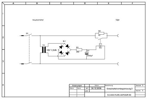
Schaltplan zur Einschaltstrombegrenzung
A B C D E F 1 Hauptschalter Säge 2 S1 R2 47 Rel1 Tr1 Br1 R1 C1 3 18V 1,5VA 280 2000µF 4 Änderungen Datum gez. Bezeichnung Blatzzahl 1 Datum Name 30.12.2006 Einschaltstrombegrenzung 2 gepr.: Blatt-Nr.: 1 (c
in „Einschaltstrombegrenzung“ · Analoge Elektronik und Schaltungstechnik · · Schaltpläne
-
PDF
Olympia-EKM-2000.pdf
normalen Wert ein, sobald diese Störungen beseitigt sind. Umwelt- und Arbeitsbedingungen - Temperatur 5C° bis 40C° - Maximale relative Luftfeuchtigkeit: 90% - Für den ausschließlichen Innengebrauch PFLEGEANWEISUNGEN • Bitte trennen Sie das Gerät vor dessen Reinigung immer zuerst vom Stromnetz. • Verwenden
in „Netzteil EA-PS 7150-04A brummt - Fehler?“ · Analoge Elektronik und Schaltungstechnik ·
-
Datei
z1.html
> i1 = i2 + i3</li> </ul> </div> <div style="display:inline-block"> <svg xmlns="http://www.w3.org/2000/svg" version="1.1" width="300px" height="200px" viewbox="0 0 300 200" > <rect x='50' y='100' width='50' height='20' /> <rect x='150' y='50' width='50' height='20' /> <line x1='170' y1='90' x2='170'
in „Wechselstrom Paradoxon“ · Analoge Elektronik und Schaltungstechnik ·
-
Datei
Zeigerdiagramm.txt
> i1 = i2 + i3</li> </ul> </div> <div style="display:inline-block"> <svg xmlns="http://www.w3.org/2000/svg" version="1.1" width="300px" height="200px" viewbox="0 0 300 200" > <rect x='50' y='100' width='50' height='20' /> <rect x='150' y='50' width='50' height='20' /> <line x1='170' y1='90' x2='170'
in „Röhrenamp: Snubber für Standby Schalter?“ · Analoge Elektronik und Schaltungstechnik ·
-
Datei
Zeigerdiagramm_komplex.html
> i1 = i2 + i3</li> </ul> </div> <div style="display:inline-block"> <svg xmlns="http://www.w3.org/2000/svg" version="1.1" width="300px" height="200px" viewbox="0 0 300 200" > <rect x='50' y='100' width='50' height='20' /> <rect x='150' y='50' width='50' height='20' /> <line x1='170' y1='90' x2='170'
in „3 Phasen + Neutral = Leitungsdurchmesser ?“ · Haus & Smart Home ·
-
Datei
Zeigerdiagramm_komplex.html
> i1 = i2 + i3</li> </ul> </div> <div style="display:inline-block"> <svg xmlns="http://www.w3.org/2000/svg" version="1.1" width="300px" height="200px" viewbox="0 0 300 200" > <rect x='50' y='100' width='50' height='20' /> <rect x='150' y='50' width='50' height='20' /> <line x1='170' y1='90' x2='170'
in „Kabellänge und Verkabelung bei Partys und Co.“ · Analoge Elektronik und Schaltungstechnik ·
-
Datei
Zeigerdiagramm_komplex.txt
> i1 = i2 + i3</li> </ul> </div> <div style="display:inline-block"> <svg xmlns="http://www.w3.org/2000/svg" version="1.1" width="300px" height="200px" viewbox="0 0 300 200" > <rect x='50' y='100' width='50' height='20' /> <rect x='150' y='50' width='50' height='20' /> <line x1='170' y1='90' x2='170'
in „2 Trenntrafos 230V - angeschlossen über 2 verschiedene Phasen“ · Analoge Elektronik und Schaltungstechnik ·
-
PDF
powermonitor_pro.pdf
den Grdßenordnungen 200 1OOh-9999h I h netzsynchron bis 350 W (t B. 300 W-Halogenscheinwerfer) und 2000 W (z B. elektrischer 10,OOkh - 65,53kh 10h netzsynchron Helzkdrper oder Hetzplatte). Scheinleistung o,o VA -999.9 VA Die Kdlibnerung selbst erfolg in drei Schritten: Einmal ohne Last, zweimal mit 0.1
in „[V] Mehr Platz im Haus“ · Markt ·
-
PDF
GRM32B7U3D221JW31_EC-data.pdf
Temp.Chara. Cap.Value Cap.Tol Volt. Durability (%Rated Volt.) GRM32B7U3D221JW31 3225M/1210 U2J 220pF +/-5% 2000V 120% 1. Dimension 3. Impedance/ESR-Frequency Equipment:Impedance/Network Analyzer ] Ω R E e L W T n 3.2+0.2/-0.2 2.5+0.2/-0.2 1.25+0/-0.3 d e m I 2. Capacitance, Q and I.R. Specifications Measuring
in „SMD-Kerko an 1200Vss und 30MHz - welcher Typ wäre geeignet?“ · Analoge Elektronik und Schaltungstechnik ·
-
PDF
GP85AAAHCB.pdf
year. o 1 Overcharge No conspicuous deformation and/or V 0.9 1000mA 14 0mA 200mAA leakage 0.8 (0.5C) (0.2C) (0.1C) Weight : 14.0g (0.5C) (0.2C) (0.1C) Internal Resistance : Average 40mΩ upon fully charged 0.7 (Range 20 – 60mΩ) at 1000Hz 0 2 4 6 8 10 12 14 Discharge Time (Hrs) Max. Charging Voltage
in „Pummer Schaltung“ · Mikrocontroller und Digitale Elektronik ·
-
PDF
Elektor_Vorlage_974078-D.pdf
bis 2000 VA schalten, was K1 * see text * voir texte Ω R7 für nahezualleVerbraucher imHaus- * siehe Text C2 C3 Re1 1 5W halt mehr als ausreichend ist. Die * Versorgung für die Relaisspule wird B250C1500 40Vµ
in „Einschaltverzögerung Widerstand“ · Analoge Elektronik und Schaltungstechnik ·
-
PDF
RDA5807SP.pdf
RDA5807SP FM Tuner V1.1 3 3 Package Thickness Volume mm Volume mm <350 ≥350 o o <2.5mm 240 + 0/-5 C 225 + 0/-5 C ≥2.5mm 225 + 0/-5 C 225 + 0/-5 C Table – II SnPb Eutectic Process – Package Peak Reflow Temperatures 3 3 3 Package Volume mm Volume mm Volume mm Thickness <350 350-2000 >2000 o o o <1.6mm 260 + 0 C * 260 + 0 C * 260 + 0 C * o o o 1.6mm – 2.5mm 260 + 0 C * 250 + 0 C * 245 + 0 C * ≥2.5mm 250 + 0 C * 245 + 0 C * 245 + 0 C * *Tolerance : The device manufacturer/supplier shall assure process compatibility
in „Hilfe benötigt bei RDA5807SP Ansteuerung“ · Mikrocontroller und Digitale Elektronik ·
-
Datei
enc28j60.h
indicator bits. // All-bank registers #define EIE 0x1B // - Register address (bits 0-4) #define EIR 0x1C // - Bank number (bits 5-6) #define ESTAT 0x1D // - MAC/PHY indicator (bit 7) #define ECON2 0x1E // #define ECON1 0x1F // // Bank 0 registers #define ERDPTL (0x00|0x00) // #define ERDPTH (0x01|0x00)
in „Atmega1280 Webserver stürzt ab“ · Mikrocontroller und Digitale Elektronik ·
-
Datei
main.c
/** ****************************************************************************** * @file : main.c * @brief : Main program body ****************************************************************************** * @attention * * <h2><center>© Copyright (c) 2021 STMicroelectronics. * All rights reserved
in „Phasenanschnitt funktioniert nicht richtig“ · Analoge Elektronik und Schaltungstechnik ·
-
PDF
LeadedDisks__B57891__M891.pdf
: ▯40 °C< 2% No visible cycling 60068-2-14 Upper test temperature: 125 °C damage Number of cycles: 100 Endurance P max 200 mW < 3% No visible t: 1000 h damage Long-term stability Temperature: 70 °C < 5% No visible
in „NTC - Frage zum Verständnis“ · Mikrocontroller und Digitale Elektronik ·
-
Datei
Test.txt
+I2C_WRITE); if ( SlaveError ) { i2c_stop(); PORTD = (1<<PD7); } i2c_stop(); while(1) { i2c_start_wait(RX8564+I2C_WRITE); i2c_write(0x02); i2c_rep_start(RX8564+I2C_READ); Sekunden = i2c_readAck(); Minuten = i2c_readAck(); Stunden = i2c_readAck(); Tag= i2c_readAck(); Tag_Name = i2c_readAck(); Monat =i2c_readAck(); Jahr = i2c_readNak(); i2c_stop(); Sekunden &= 0x7F; Minuten &= 0x7F; Stunden &= 0x3F; Tag &= 0x3F
in „Tasterabfrage in ISR“ · Mikrocontroller und Digitale Elektronik ·
-
PDF
Porting_ucOSII_to_ARM.pdf
). [8] J. J. Labrosse. Embedded Systems Building Blocks: Complete and Ready-to-Use Modules in C. CMP Books, 2nd edition, 2000. (www.micrium.com). [9] Philips. Nesting of interrupts on the LPC2000. Application Note, 2005. (www.philips.com). [10] Philips. Volume 1: LPC213x User Manual. User Manual
in „uC/OS-II portieren“ · Mikrocontroller und Digitale Elektronik ·
-
PDF
MemoryMapping.pdf
0800 Port C 0xC000 0000 Port B 0x4002 0400 Port A 0x4002 0000 reserved 0x4001 3C00 5 USART1 0x4001 3800 0x4001 3400 reserved 0xA000 0000 SPI1 0x4001 3000 reserved 0x4001 2800 ADC 4 0x4001 2400 reserved 0x4001 1400
in „Pointer auf Hardwareadresse in Mikrocontroller“ · Mikrocontroller und Digitale Elektronik ·
-
PDF
limitor.pdf
/ 60 Hz Maßzeichnung Q8 min. Strom: 5 V / 20 mA max. Schaltleistung: 2,5 A cos Φ1,00 / 250 V, 150°C, 3000 Zyklen 3,0 A cos Φ0,45 / 230 V, 135°C, 3000 Zyklen 4,0 A cos Φ0,45 / 230 V, 135°C, 2000 Zyklen 6,5 A cos Φ1,00 / 120 V, 120°C, 100 Zyklen Schalttemperatur: 40°C – 120°C (150°C), ±5 K alternativ: Wirkungsweise: 1.C (3000 Zyklen 5er Gehäuse: 2.C (max. Drift ±5 K) H 4,0 x B 8,0 x L 16,0 max. Dauertemperatur: 160°C Haltewiderstand: 0,1 kΩ - 60 kΩ,bitte Sicherheitshinweise beachten*er Gehäuse: H 3,6 x B 8,0 x L 14,5
in „Trenntrafo löst Sicherung aus“ · Analoge Elektronik und Schaltungstechnik ·
-
PDF
1MHz_Schaltung_GLEICHRICHTUNG_V2.pdf
1MHz Spitzenwert-Gleichrichtung V +12V R Bernhard.Erfurt@gmx.de k ca 200mV 2 R 01/2013 k 1 k 5 k 6 C2 BC 546 1 R 1 R D1 BAT48 C4 100n 1µ k C3 0 2 k 1 k 3 1 R 1 R 100n 2 R 1MHz HF 10....2000 mV
in „Spektrumanalyser Frequenzspektrometer Eigenbau bis 1MHz“ · Analoge Elektronik und Schaltungstechnik ·
-
PDF
AVRDUDE.pdf
How-To: Programmieren des AVR-Ctrl mit AVRDude unter Windows 2000 Copying the driver to the windows directory target file: C:\WINNT\giveio.sys The system cannot find the file specified. Nachdem ich das AVR-Ctrl Experimentierboard zusammengebaut hatte, wollte ich zumindest
in „Frage bezüglich Programmierung auf AVC-Ctrl“ · Mikrocontroller und Digitale Elektronik ·
-
PDF
DE_20DE0001_TECHNIK_LEITUNGSSCHUTZSCHALTER.PDF
B Auslösecharakteristik C LS-Schalter: MBS, MBN, NBN LS-Schalter: MCS, MCN, NCN FI/LS-Schalter FI/LS-Schalter 10000 6000 2 Punkte 1 2 3 4, , Punkte 1 2 3 4, , 3600 2000 DC siehe Tabelle 1 und 2 siehe Tabelle 1 und 2 1600 400
in „Heizstrahler Schalterkontakt brennt fest“ · Analoge Elektronik und Schaltungstechnik ·
-
PDF
SEMIKRON_DataSheet_SKT_1200_01890430.pdf
SKT 1200/18 E Absolute Maximum Ratings Symbol Conditions Values Unit Chip T(AV) Tc= 85 °C 1200 A sinus 180° Tc= 100 °C 840 A TSM Tj= 25 °C 30000 A 10 ms Tj= 125 °C 25500 A it T = 25 °C 4500000 A²s 10 ms j Tj= 125 °C 3251250 A²s Capsule Thyristor VRSM 1800 V V 1800 V RRM VDRM 1800 V (di/dcr
in „Warum schaltet mein Thyristor nicht durch?“ · Analoge Elektronik und Schaltungstechnik ·
-
PDF
AD7609.pdf
8UsingReadAfterConversion 3000 1600 NO OVERSAMPLING OVERSAMPLING BY 4 13841373 1400 2500 2363 2394 S S E1200 1167 C N 1062 N E E2000 R1000 R U U C 840 C C 800 727 O1500 1340 O F O O 1191 R 600 R E 492 E1000 B 450 B M 400 U N N 500 422 210 219 341 200 100 27 83 49 79 2 10 32 11 2 1 0 5 8 6 0 0 - –9 –8 –7 –6 –5 –4 –
in „Unterschiedliches Verhalten innerhalb der gleichen IC-Reihe“ · Analoge Elektronik und Schaltungstechnik ·
-
PDF
AD7609.pdf
8UsingReadAfterConversion 3000 1600 NO OVERSAMPLING OVERSAMPLING BY 4 13841373 1400 2500 2363 2394 S S E1200 1167 C N 1062 N E E2000 R1000 R U U C 840 C C 800 727 O1500 1340 O F O O 1191 R 600 R E 492 E1000 B 450 B M 400 U N N 500 422 210 219 341 200 100 27 83 49 79 2 10 32 11 2 1 0 5 8 6 0 0 - –9 –8 –7 –6 –5 –4 –
in „SPI-Kommunikation von AD-Wandler zu Raspberry Pi“ · Mikrocontroller und Digitale Elektronik ·
-
PDF
DE_16DE0001_TECHNIK_LEITUNGSSCHUTZSCHALTER.pdf
Auslösecharakteristik D Tabelle 1 LS-Schalter: NDN Auslösung Auslösecharakteristik B Auslösecharakteristik C 16000 6 kA AC DC AC DC 4000 2 LS-Schalter 2000 ~ 50 Hz ~ 50 Hz I 1,13 In 1,13 In 1,13 In 1,13 In 6000 1 t1 400 DC 2 It2 1,45 In 1,45 In 1,45 In 1,45 In r l 200 3 Irm1 3 In 3 In 5 In 5 In h 100 s c .
in „Fi-Schutzschalter nur für die Hälfte der Wohnung?“ · Haus & Smart Home ·