-
PDF
STM32U599ZJT_Rev.0.2_SCH.pdf
STM32U599ZJT_Rev.0.2_SCH.pdf
in „STM32U599 reagiert nicht: Keine Funktion auf dem Custom Board“ · Mikrocontroller und Digitale Elektronik ·
-
Datei
main.c
#include "stm32f4xx_conf.h" #define MAX_BUFFER_LENGTH 12 //Maximale Receive-Buffer-Länge volatile char received_string[MAX_BUFFER_LENGTH - 1]; //Receive-String-Buffer void Delay(__IO uint32_t nCount) { while(nCount
in „ARM Einstieg - Wie weitermachen?“ · Mikrocontroller und Digitale Elektronik ·
-
Datei
main.c
#include "stm32f4xx_conf.h" #define MAX_BUFFER_LENGTH 12 //Maximale Receive-Buffer-Länge volatile char received_string[MAX_BUFFER_LENGTH - 1]; //Receive-String-Buffer void Delay(__IO uint32_t nCount) { while(nCount
in „ARM Einstieg - Wie weitermachen?“ · Mikrocontroller und Digitale Elektronik ·
-
PDF
TARGET__Ethernetshield_2_.T3000.pdf
10µF C6 IC3d 100NF 1 IC3 T c S 74LV14DSMD V E IC3a 2 R MR Reset 4 D T 74LV14DSMD G IC3b 1 2 P P J J STM812 74LV14DSMD IC3c 74LV14DSMD IC3f 74LV14DSMD R R g g E E l l O O n n 74LV14DSMD P P A A
in „Autorouter bei Target“ · Platinen ·
-
Datei
main.h
#endif /* Includes ------------------------------------------------------------------*/ #include "stm32f1xx_hal.h" /* Private includes ----------------------------------------------------------*/ /* USER CODE BEGIN Includes */ /* USER CODE END Includes */ /* Exported types --------------------------
in „[Pollin] Grafik Display Anschluss Verständnisfragen“ · Mikrocontroller und Digitale Elektronik ·
-
Datei
analogReadSerial.ino
// read analog pin and print it via software serial // STM32F4 Discovery #define ANALOGPIN PA1 #define SOFTSERIAL_BAUDRATE 115200 #define SOFTSERIALPIN_TX PC1 #define USERBUTTON PA0 #define GREENLED PD12 #define ORANGELED PD13 #define GREDLED PD14 #define BLUELED
in „STM32F4 Discovery Arduino“ · Mikrocontroller und Digitale Elektronik ·
-
Datei
dogm.c
17:19 * Author: Chris */ #include <stdint.h> #include "LCD_DOGM_SPI.h" #include "main.h" #include "stm32f1xx_hal.h" void delay_ms(uint16_t); void delay_us(uint16_t); //////////////////////////////////////////////////////////////////////// // Sendet 8 uint8_t zum LCD extern SPI_HandleTypeDef hspi1; static
in „DOGM - 163 Initialisierung +5V SPI“ · Mikrocontroller und Digitale Elektronik ·
-
PDF
file.pdf
Hardware and layout UM1472 Figure 6. STM32F407VGT6 block diagram ##-▯DATA▯2!-▯▯▯▯+" %XTERNAL▯MEMORY #,+▯▯.%▯;▯▯▯=▯▯!;▯▯▯▯= CONTROLLER▯▯&3-# $;▯▯▯▯=▯▯/%.▯▯7%.▯▯ .*4234▯▯*4$)▯▯ !("▯ 32!-▯▯032!-▯▯./2▯&LASH▯ .",;▯▯▯=▯▯.,▯▯.2%' *4$/▯37$▯▯*4$/ *
in „STM32 FW_LIB wozu dient RCC_APB2PeriphClockCmd?“ · Mikrocontroller und Digitale Elektronik ·
-
Datei
lcd_routines.h
#ifndef LCD_ROUTINES_H #define LCD_ROUTINES_H #include "stm32f4xx_gpio.h" #include "time.h" #ifndef F_CPU #define F_CPU 3686400 #endif #define LCD_PORT GPIOD #define LCD_DDR DDRD #define LCD_DB GPIO_Pin_0 #define LCD_RS GPIO_Pin_4 #define LCD_EN GPIO_Pin_5 #
in „Anag Vision gibt keine Zeichen aus“ · Mikrocontroller und Digitale Elektronik ·
-
Datei
Seriell_Empfangen_USART.txt
#include "stm32f0xx.h" #define Input1 GPIOB, GPIO_Pin_0 #define Input2 GPIOB, GPIO_Pin_1 #define Input3 GPIOB, GPIO_Pin_2 #define Input4 GPIOB, GPIO_Pin_6 #define Output1 GPIOA, GPIO_Pin_8 #define Output2 GPIOB,
in „STM32f0xx UART“ · Mikrocontroller und Digitale Elektronik ·
-
Datei
Seriell_Senden_USART.txt
#include "stm32f0xx.h" #define Input1 GPIOB, GPIO_Pin_0 #define Input2 GPIOB, GPIO_Pin_1 #define Input3 GPIOB, GPIO_Pin_2 #define Input4 GPIOB, GPIO_Pin_6 #define Output1 GPIOA, GPIO_Pin_8 #define Output2 GPIOB,
in „STM32f0xx UART“ · Mikrocontroller und Digitale Elektronik ·
-
Datei
eeprom_test.c
/* * Lesen und Schreiben eines externen EEPROMs 24C02 per I2C (STM32) * oder des internen EEPROMS (AVR), Test * * Created: 04.02.2014 * Author: Nicolas */ #include <stdint.h> #include <stdio.h> // printf_P #include "../src_avrcom/pgmspace.h" #include "../src_avrcom
in „STM32 I2C mit EEPROM - funktioniert nur zuverlässig mit Bus-Sniffer“ · Mikrocontroller und Digitale Elektronik ·
-
Datei
main.c
#include "stm32f4xx_conf.h" GPIO_InitTypeDef GPIO_InitStructure; TIM_TimeBaseInitTypeDef TIM_TimeBaseStructure; void TIM3_IRQHandler(void) { if (TIM_GetITStatus(TIM3, TIM_IT_Update) != RESET) { TIM_ClearITPendingBit
in „Frage/Problem mit Timer STM32F4Discovery“ · Mikrocontroller und Digitale Elektronik ·
-
Datei
boards.local.txt
ARM_BOARDBLUEPILL boardbluepill.hide= boardbluepill.vid.0=0x0483 boardbluepill.pid.0=0x5740 boardmarple.name=STM32 Marple Bootloader boardmarple.build.board=ARM_BOARDMARPLE boardmarple.hide= boardmarple.vid.0=0x1EAF boardmarple.pid.0=0x0004 boardDMX512.name=DMX Adapter boardDMX512.build.board=BOARDDMX512 boardDMX512
in „Weiß jemand, was für ein Atmega-Board das ist?“ · Mikrocontroller und Digitale Elektronik ·
-
Datei
main.h
#endif /* Includes ------------------------------------------------------------------*/ #include "stm32f0xx_hal.h" /* Private includes ----------------------------------------------------------*/ /* USER CODE BEGIN Includes */ #include "taste_yt_remote.h" #include "taste_yt_remote1.h" /* USER CODE END
in „Programmierung - Doppelbelegung einer Taste“ · Mikrocontroller und Digitale Elektronik ·
-
Datei
SimpleSoftSerial.ino
// print with manual made software serial the // by the user button selected blinking led // STM32F4 Discovery #define SOFTSERIAL_BAUDRATE 115200 #define SOFTSERIALPIN_TX PC1 #define USERBUTTON PA0 #define GREENLED PD12 #define ORANGELED PD13 #define GREDLED PD14 #define BLUELED PD15 #define REDLEDOTGOVERCURRENT
in „STM32F4 Discovery Arduino“ · Mikrocontroller und Digitale Elektronik ·
-
Datei
nrf24l01_drv.h
Files ----------------- */ /* -------------- System Include Files / Librarys -------- */ #include "stm32f10x_conf.h" /* -------------- Projekt Include Files ---------------- */ /* -------------- Defintionen ---------------------------- */ #define IRQ_LINE EXTI_Line2 #define IRQ_HDL EXTI2_IRQn #define
in „Basteltip: STM32F103 DIP40 Board“ · Mikrocontroller und Digitale Elektronik ·
-
Datei
main.c
#include "stm32f10x.h" #include "sda5708.h" #define LED_OFF() GPIO_SetBits(GPIOC , GPIO_Pin_13) #define LED_ON() GPIO_ResetBits(GPIOC , GPIO_Pin_13) void init_led(); void init_buttons(); void systick_delay(int ticks
in „STM32 Linker-Problem (overlaps section.) + Clock zu langsam?“ · Mikrocontroller und Digitale Elektronik ·
-
PDF
semicon.pdf
SOT23 2860 RECT LP2980IM5X 5,0V regulátor SOT23 2840 RECT LP2980IM5 3,6V regulátor SOT23 240 RECT STM L7808CD2T TR regulátor D2pack 1000 RECT MC 33269 3,3V D2pack 1000 x LM1086 CS ADJ D2pack 140 x ZMM 6V8 SMD zener SOT23 1680 x BZX84C 5V1 LT1 SMD zener SOT23 3000 x BZX84C 5V6 7 SMD zener SOT23 8800
in „4" TFT für 7,97€“ · Markt ·
-
Datei
sysf103_init.h
/* ------------------------------------------------------------- sysf103_init.h initialisiert MCU STM32F103C8 fuer einen "allgemeinen" Gebrauch. Hardware : STM32F103C8 IDE : keine (Editor / make) Library : libopencm3 Toolchain : arm-none-eabi 28.09.2016 R. seelig ------------------------------------
in „Einstieg Mikrocontroller Atmel“ · Mikrocontroller und Digitale Elektronik ·
-
Datei
config.c
/* Portbelegungen und Konfiguration: */ #include "StdTypes.h" #include "STM32F103all.h" #include "startup.h" #include "config.h" /* Portbelegungen und Konfiguration: ================================= Diese Konfiguration ist für den STM32F103C8T6, also im LQFP-48 Gehäuse. Zu
in „MINOS - Minos Is No Operating System“ · Projekte & Code ·
-
Datei
eeprom.c
/ Librarys -------- */ /* ---------------- System Include Files -------------------- */ #include "stm32f10x_conf.h" #include "system_stm32f10x.h" /* ----------------- C Standard Include Files --------------- */ #include <stdbool.h> #include <stdint.h> #include <stdio.h> #include <stdlib.h> #include
in „Lebensdauer von lokalen Variablen“ · Softwareentwicklung ·
-
Datei
eeprom.c
/ Librarys -------- */ /* ---------------- System Include Files -------------------- */ #include "stm32f10x_conf.h" #include "system_stm32f10x.h" /* ----------------- C Standard Include Files --------------- */ #include <stdbool.h> #include <stdint.h> #include <stdio.h> #include <stdlib.h> #include
in „STM32F103: EEPROM Abstürze abfangen“ · Mikrocontroller und Digitale Elektronik ·
-
Datei
usart_nrf.h
#ifndef __USART_NRF_H #define __USART_NRF_H #ifdef DTU3PRO #include "stm32f4xx.h" #define UsartNrf USART3 #else #include "stm32f10x.h" #define UsartNrf USART2 #endif #include <math.h> #include <stdlib.h> #include <stdio.h> #include <string.h> #include <stdbool.h> #include
in „Wechselrichter Hoymiles HM-xxxx 2,4 GhZ Nordic Protokoll?“ · Mikrocontroller und Digitale Elektronik ·
-
Datei
config.c
/* Portbelegungen und Konfiguration: */ #include "StdTypes.h" #include "STM32F103all.h" #include "startup.h" #include "config.h" /* Portbelegungen und Konfiguration: ================================= Diese Konfiguration ist für den STM32F103C8T6, also im LQFP-48 Gehäuse. Zu
in „Problem mit Clock Configuration beim STM32G031“ · Mikrocontroller und Digitale Elektronik ·
-
PDF
Elektronik.pdf
1 N 2 3 4 5 6 G BT1 STM32H753 534-1027 +3.3V C11 C12 FB1 R2 Ferrite_Bea+3.3V GND 1.6 Sheet: Schalter und Taster Sheet: Drivers Sheet: Analog 10u 100n TMC_en TMC_en Tast_Input J2 6 1 2 5 7 0 2 Tast_Input P_diff ADC1_5 Conn_
in „50ns Delay mit STM32H7“ · Mikrocontroller und Digitale Elektronik ·
-
PDF
ABX00042-ABX00045-ABX00046-datasheet.pdf
Portenta H7 Collective Datasheet 1 Features 1.1 Microcontroller Component Details Supported boards ST STM32H747XI Processor Dual Core Arm® Cortex®-M7 core at up to All 480 MHz with double-precision FPU and 16K data + 16K instruction L1 cache Arm® 32-bit Cortex®-M4 core at up to 240 MHz with FPU, Adaptive
in „Problem mit der SPI Datenübertragung zwischen einem Arduino Portenta H7 und einem ADS8684 (ADC)“ · Mikrocontroller und Digitale Elektronik ·
-
 Bild
Bild
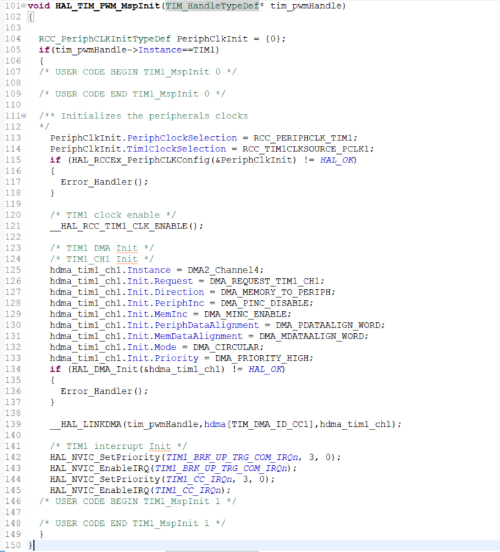
C-Code für STM32 PWM und DMA Konfiguration
void HAL_TIM_PWM_MspInit(TIM_HandleTypeDef *tim_pwmHandle) { RCC_PeriphCLKInitTypeDef PeriphClkInit = {0}; if(tim_pwmHandle->Instance==TIM1) /* USER CODE BEGIN TIM1_MspInit 0 */ /* USER CODE END TIM1_MspInit 0 */ /** Initializes the peripherals clocks */ PeriphClkInit.PeriphClockSelection = RCC_PERIPHCLK_TIM1; PeriphClkInit.TimClockSource = RCC_TIMCLKSOURCE_PCLK1; if (HAL_RCCEx_PeriphCLKConfig(&PeriphClkInit) != HAL_OK) { Error_Handler(); } /* TIM1 clock enable */ HAL_RCC_TIM1_CLK_ENABLE(); /* TIM1 DMA Init */ /* TIM1 CH1 Init */ hdma_tim1_chl.Instance = DMA2_Channel4; hdma_tim1_chl.Request = DMA_REQUEST_TIM1
in „STM32 Timer mehrere Compare Values mit DMA“ · Mikrocontroller und Digitale Elektronik · · Screenshots
-
 Bild
Bild
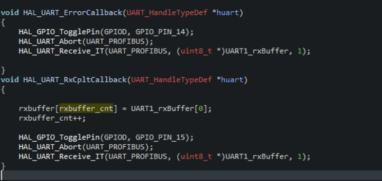
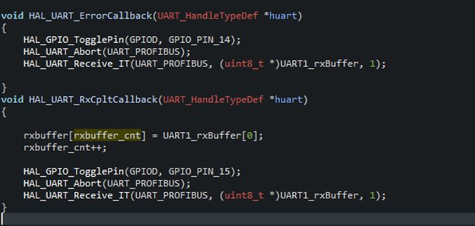
C-Code für STM32 HAL UART Callbacks
void HAL_UART_ErrorCallback(UART_HandleTypeDef *huart) { HAL_GPIO_TogglePin(GPIOD, GPIO_PIN_14); HAL_UART_Abort(UART_PROFIBUS); HAL_UART_Receive_IT(UART_PROFIBUS, (uint8_t *)UART1_rxBuffer, 1); } void HAL_UART_RxCpltCallback(UART_HandleTypeDef *huart) { rxbuffer[rxbuffer_cnt] = UART1_rxBuffer[0]; rxbuffer_cnt++; HAL_GPIO_TogglePin(GPIOD, GPIO_PIN_15); HAL_UART_Abort(UART_PROFIBUS); HAL_UART_Receive_IT(UART_PROFIBUS, (uint8_t *)UART1_rxBuffer, 1);
in „STM32F7 UART - Parität Problem“ · Mikrocontroller und Digitale Elektronik · · Screenshots
-
Datei
disasm.asm
l000030e4: 4770 bx lr l000030e6: 0000 lsls r0, r0, #0 l000030e8: 0000 lsls r0, r0, #0 l000030ea: C0C1 stm r0!, {r0, r6, r7} l000030ec: C181 stm r1!, {r0, r7} l000030ee: 0140 lsls r0, r0, #5 l000030f0: C301 stm r3!, {r0} l000030f2: 03C0 lsls r0, r0, #15 l000030f4: 0280 lsls r0, r0, #10 l000030f6: C241 stm r2!, {r0, r6} l000030f8: C601 stm r6!, {r0} l000030fa: 06C0 lsls r0, r0, #27 l000030fc: 0780 lsls r0, r0, #30 l000030fe: C741 stm r7!, {r0, r6} l00003100: 0500 lsls r0, r0, #20 l00003102: C5C1 stm r5!, {r0, r6, r7} l00003104: C481 stm
in „Flash im Cortex-M0 durch Codeinjektion ins SRAM auslesen“ · Mikrocontroller und Digitale Elektronik ·
-
Datei
linker.ld
/* Linker script for STM32F103 Cortex-M3 microcontroller */ /* $Id: linker.ld,v 1.5 2008/03/25 09:16:19 cvs Exp $ */ MEMORY { rom (rx) : ORIGIN = 0x00000000, LENGTH = 128K ram (rwx) : ORIGIN = 0x20000000, LENGTH = 20K } __rom_start
in „STM32x kein malloc mehr möglich“ · Mikrocontroller und Digitale Elektronik ·
-
Datei
images.h
#endif /* Includes ------------------------------------------------------------------*/ #include "stm32f10x.h" /** @addtogroup Embedded_GUI_Library * @{ */ /** @addtogroup Images * @{ */ /* Exported constants --------------------------------------------------------*/ /** @defgroup Images_Exported_Constants
in „STM32 24Bit Bmp nach 565RGB Format“ · Mikrocontroller und Digitale Elektronik ·
-
Datei
ds18b20.h
DS18B20_H_ /* Includes ------------------------------------------------------------------*/ #include "stm32f10x_lib.h" /* #define DS18B20_BIT GPIO_Pin_0 #define DS18B20_PORT GPIOC #define READ_DS18B20() GPIO_ReadInputDataBit(GPIOB, DS18B20_BIT) #define DIR_1WIRE_IN() {DS18B20_PORT->CRL &= 0xFF0FFFFF;DS18B20
in „STM32 DS1820“ · Mikrocontroller und Digitale Elektronik ·
-
Datei
ds18b20.c
/* Includes ------------------------------------------------------------------*/ #include "stm32f10x_lib.h" #include "ds18b20.h" #include "Param.h" #include <string.h> #include <stdio.h> #include <stdlib.h> #define in 1 #define out 0 void delay_us(vu32 nCount) { u16 TIMCounter = nCount; TIM_TimeBaseInitTypeDef
in „STM32 DS1820“ · Mikrocontroller und Digitale Elektronik ·
-
Datei
main.cpp
IO(DB4, B, 4); GPIO__IO(DB5, B, 5); GPIO__IO(DB6, D, 7); GPIO__IO(DB7, D, 6); using namespace xpcc::stm32; static bool initClock() { // use external 8MHz crystal if (!Clock::enableHse(Clock::HSE_CRYSTAL)) { return false; } Clock::enablePll(Clock::PLL_HSE, 4, 168); return Clock::switchToPll(); } void checkbusy
in „STM32F4_Discovery + LCD“ · Mikrocontroller und Digitale Elektronik ·
-
Datei
usbview.txt
---------------------------------- STM32 X-NUCLEO-LPM01A Firmware version: 1.0.1 ---------------------------------- Device Descriptor: bcdUSB: 0x0200 bDeviceClass: 0x00 bDeviceSubClass: 0x00 bDeviceProtocol: 0x00 bMaxPacketSize0: 0x40 (64
in „ST-LINK Zugriff von Mac M1 - Device nicht sichtbar“ · Mikrocontroller und Digitale Elektronik ·
-
Datei
main.c
#include "stm32f10x.h" uint32_t CRC32(uint8_t* buf, int len) { uint32_t crc = 0xFFFFFFFF; for(int i=0; i<len; i++) { uint32_t byte = buf[i]; crc = crc^byte; for(int j=7; j>=0; j--) { uint32_t mask = -(crc & 1); crc
in „STM32F103C8T6 - Fälschung von ST bestätigt“ · Mikrocontroller und Digitale Elektronik ·
-
Datei
nrf24l01_drv.h
Files ----------------- */ /* -------------- System Include Files / Librarys -------- */ #include "stm32f10x_conf.h" /* -------------- Projekt Include Files ---------------- */ /* -------------- Defintionen ---------------------------- */ #define IRQ_LINE EXTI_Line2 #define IRQ_HDL EXTI2_IRQn #define
in „[STM32F4xx] NRF24L01+ Funkmodul Source Code“ · Projekte & Code ·
-
Datei
lcd_init.h
Hardware (C) Christian Julius 3.2016 ------------------------------------------------------- */ #include "stm32f10x_conf.h" /* ------------ Standard Include Files --------------- */ #include <stdint.h> /* ------------ Special Include Files --------------- */ /* ------------ Projekt Include Files -----------
in „Basteltip: STM32F103 DIP40 Board“ · Mikrocontroller und Digitale Elektronik ·
-
Datei
dht22.c
#include "dht22.h" #include "uart.h" #include "stm32f1xx_hal.h" extern DHT22_TypeDef dht22_1; int dht22_Init(DHT22_TypeDef* dht22){ int ret = -1; #ifdef DEBUG UART_printf(dht22->debug_uart.Instance, "(I) dht22: init"); #endif ret = dht22_gpio_init(dht22
in „stm32f103 Timer Input Capture Interrupt“ · Mikrocontroller und Digitale Elektronik ·
-
Datei
lcd_init.h
Hardware (C) Christian Julius 3.2016 ------------------------------------------------------- */ #include "stm32f10x_conf.h" /* ------------ Standard Include Files --------------- */ #include <stdint.h> /* ------------ Special Include Files --------------- */ /* ------------ Projekt Include Files -----------
in „Lebensdauer von lokalen Variablen“ · Softwareentwicklung ·
-
Datei
main.cpp
mTimUserHandle); // check against system clock timeStart = us_ticker_read(); } int main() { printf("Hello from STM32F407VE\n"); initHardwareTimeout(); int timeout = 2000; // µs startHardwareTimeout(timeout); ThisThread::sleep_for(1000); // sleep for 1s and let timeout ISR execute int measuredDiff = timeNow-timeStart
in „STM32F407 OnePulse Timer“ · Mikrocontroller und Digitale Elektronik ·
-
Datei
st8readihx.c
n\n", filename); return 2; } byteanz= readhexfile(&filename[0],0)-0x8000; fprintf(stderr,"Device : STM8S103F3\n"); fprintf(stderr,"Program : at address 0x8000 %d Bytes (%.1f%% full)\n",byteanz, (float)(byteanz*100)/0x2000); return 0; }
-
PDF
pinout_blackpill.pdf
1 1 A A P P K S STM32F103C8T6 BLACKPILL C M J J K O D C D 3 G W W 3 S S 37 34 5V 5V CK3 T1BKIN NSS2 SMBAI2 PB12 B12 25 5V 22 5V B11 PB11 SDA2 RX3 T2C4N CTS3 T1C1N SCK2 PB13 B13 26 5V 21 5V B10 PB10 SCL2 TX3 T2C3N RTS3
in „pinout blackpill STM32F103C8T6“ · Mikrocontroller und Digitale Elektronik ·
-
PDF
corrupted-content-of-the-backup-domain.pdf
STM32G471xx/473xx/474xx/483xx/484xx System 2.2.6 Corrupted content of the backup domain due to a missed power-on reset after this domain supply voltage drop Description The backup domain reset may be missed
in „Auch bei den STM32 funktioniert Reset nicht richtig :(“ · Mikrocontroller und Digitale Elektronik ·
-
Datei
usart.c
------------------------------------------------------------------*/ #include <stdio.h> #include "stm32f10x.h" #include "usart.h" struct __FILE { int handle; }; FILE __stdout; FILE __stdin; /** Bevor Zeichen mit printf() ausgegeben werden, muss das Ausgabeziel * (USART1 bzw. USART2) festgelegt werden
in „[STM32] CMD0 liefert immer 0xFF zurück“ · Mikrocontroller und Digitale Elektronik ·
-
Datei
spi1.h
#endif /* Includes ------------------------------------------------------------------*/ #include "stm32f4xx.h" #ifndef NULL #define NULL 0 #endif /* SPI1 Interface pins */ #define SPI1_CLK RCC_APB2Periph_SPI1 #define SPI1_CLK_INIT RCC_APB2PeriphClockCmd #define SPI1_SCK_PIN GPIO_Pin_5 #define SPI1_SCK_GPIO_PORT
in „STM32 SPI Init“ · Mikrocontroller und Digitale Elektronik ·
-
Datei
LCD.h
Includes ------------------------------------------------------------------*/ #include <math.h> #include "stm32f4xx.h" #include "config.h" #include "AsciiLib.h" /* Private define ------------------------------------------------------------*/ #define USE_16BIT_PMP /*******************************************
in „STM32F4 mit TFT Codeverständnis“ · Mikrocontroller und Digitale Elektronik ·
-
Datei
LCD.h
Includes ------------------------------------------------------------------*/ #include <math.h> #include "stm32f4xx.h" #include "config.h" #include "AsciiLib.h" /* Private define ------------------------------------------------------------*/ #define USE_16BIT_PMP /*******************************************
in „STM32F4 Discovery + TFT + FSMC“ · Mikrocontroller und Digitale Elektronik ·
-
Datei
config.h
#ifndef _CONFIG_H #define _CONFIG_H #include <stdio.h> #include "stm32f4xx.h" /** * @brief Definition for COM port1, connected to USART1 */ #define Open207V_USART USART3 #define Open207V_USART_CLK RCC_APB1Periph_USART3 #define Open207V_USART_TX_PIN GPIO_Pin_10 #define
in „STM32F4 Discovery + TFT + FSMC“ · Mikrocontroller und Digitale Elektronik ·