-
PDF
Grillen_Fuchs_Beschreibung_V1_0.pdf
131, 122, 128, 127, 124, 129, 124, 128, 126, 128, 126, 126, 127, 124, 129, 124, 127, 128, 0 }; void pwm_setup (void) { // Set Timer 0 prescaler to clock TCCR0B |= (1 << CS00); // Set to 'Fast PWM' mode TCCR0A |= (1 << WGM01) | (1 << WGM00); // Clear OC0B output on compare match, upwards counting. TCCR0A
in „ATTINY 433MHz Fuchssender mit akustischem Grillen-Sound“ · Projekte & Code ·
-
PDF
Grillen_Fuchs_Beschreibung_V1_1.pdf
131, 122, 128, 127, 124, 129, 124, 128, 126, 128, 126, 126, 127, 124, 129, 124, 127, 128, 0 }; void pwm_setup (void) { // Set Timer 0 prescaler to clock TCCR0B |= (1 << CS00); // Set to 'Fast PWM' mode TCCR0A |= (1 << WGM01) | (1 << WGM00); // Clear OC0B output on compare match, upwards counting. TCCR0A
in „ATTINY 433MHz Fuchssender mit akustischem Grillen-Sound“ · Projekte & Code ·
-
PDF
ai8051u_extract_English.pdf
clock source, at 125°C it is recommended to keep the PWM input clock below 138 MHz; at 105°C the PWM input clock may use 144 MHz. (When the chip powers up normally, powers up after reset, watchdog reset, or low-voltage-detect reset, it initially executes
in „[8051/80251/STC32] Vorstellung AI8051U - eine "AI"-MCU aus China im DIP40 Package ;)“ · Mikrocontroller und Digitale Elektronik ·
-
Bild
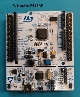
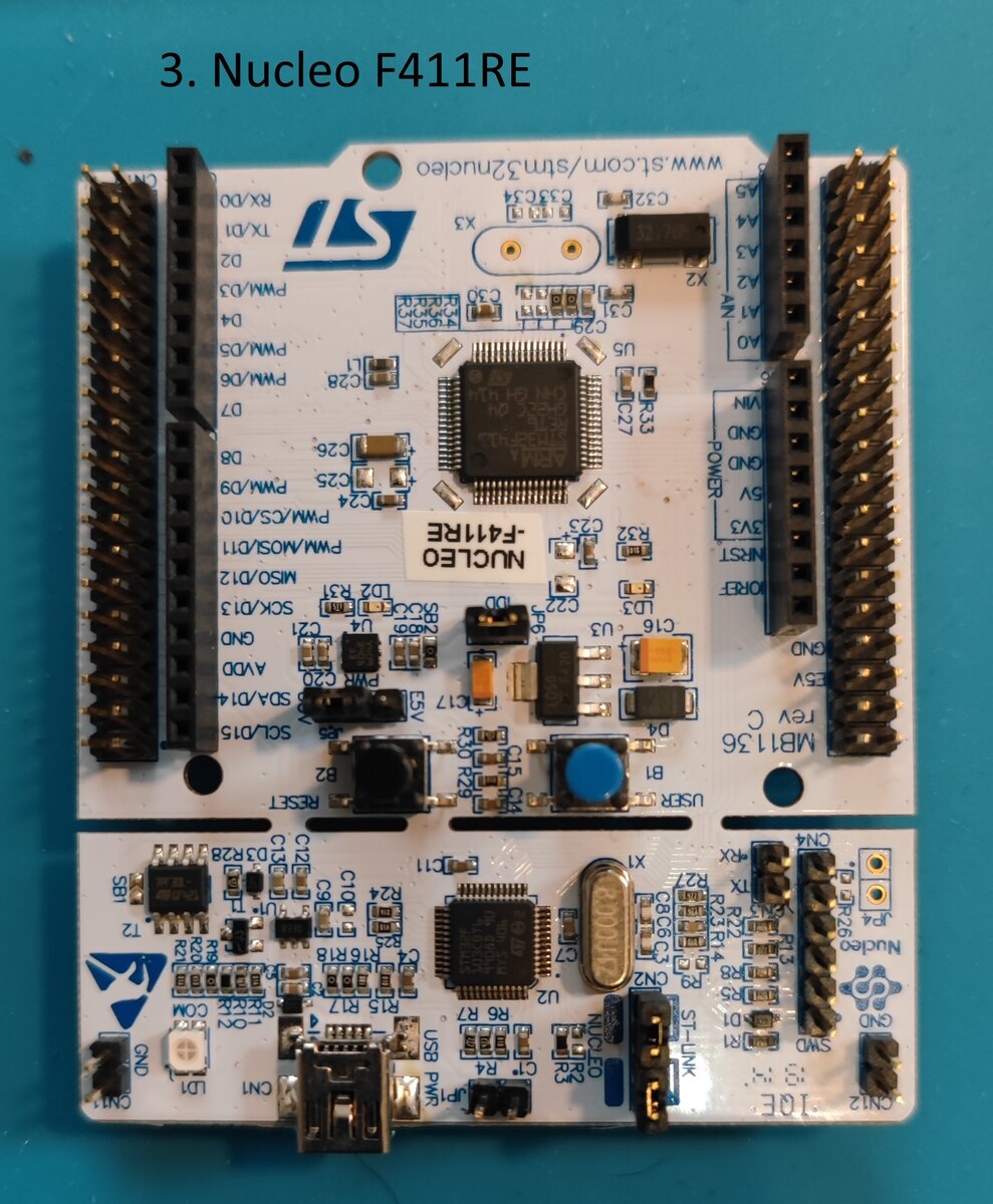
STM32 Nucleo-F411RE Development Board
3. Nucleo F411RE ST stm32.com/stm32nucleo RX/D0 TX/D1 D2 PWM/D3 D4 PWM/D5 CLK PWM/CS/D10 PWM/MOSI/D11 MISO/D12 SCK/D13 SCL/D15 AN0 bis AN7 GND 5V 3V3 NRST USER RESET USB ST-LINK NUCLEO-F411RE MB1136 rev C
in „[V] Sammlung diverser Entwicklungsboards“ · Markt · · Platinenfotos
-
Bild
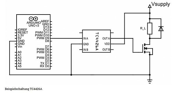
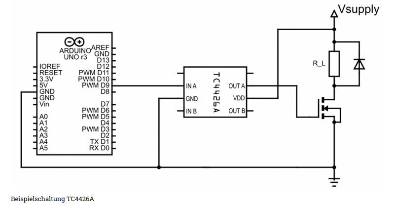
Schaltplan mit Arduino Uno und TC4426A Treiber
ARDUINO UNO r3, IOREF, RESET, 3.3V, 5V, GND, GND, Vin, A0, A1, A2, A3, A4, A5, AREF, D13, D12, PWM D11, D10, PWM D9, D8, D7, PWM D6, D5, D4, PWM D3, D2, TX D1, RX D0, TC4426A, IN A, OUT A, GND, VDD, IN B, OUT B, Vsupply, R_L, Beispielschaltung TC4426A
in „IGBT Modul SKM150GAL12T4 brennt durch“ · Analoge Elektronik und Schaltungstechnik · · Schaltpläne
-
Datei
sound.txt
" $crystal = 8000000 Config Portd = Output Config Serialin = Buffered , Size = 255 Config Timer1 = Pwm , Pwm = 8 , Compare A Pwm = Clear Up , Compare B Pwm = Clear Down , Prescale = 256 Dim A As Byte Enable Interrupts Do A = Inkey() If A > 0 Then Compare1a = A Compare1b = A End If Loop
in „sounddatei übertragen per uart“ · Mikrocontroller und Digitale Elektronik ·
-
Bild
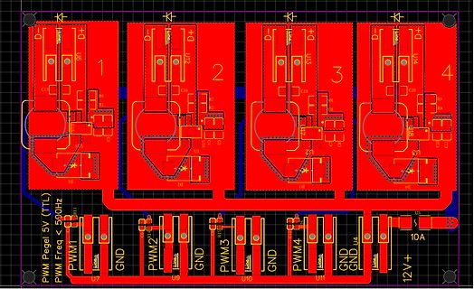
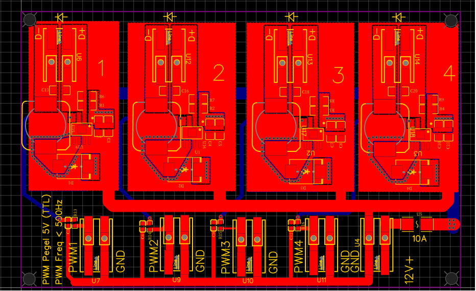
PCB-Layout einer Leistungselektronik-Schaltung
D+ D- U6 C15 R6 R1 1 U10 D1 D2 R23 PWM1 U7 GND PWM2 U9 GND PWM3 U10 GND PWM4 U11 GND GND U4 12V+ 10A U14 C26 R9 R4 U13 C11 C12 U2 R18 R17 C18 U3 D3 D4 2 3 4
in „Adressierbare High Power RGBW LEDs per DMX512“ · Mikrocontroller und Digitale Elektronik · · Layouts
-
Bild
Foto einer Leiterplatte und Schaltplan-Ausschnitt
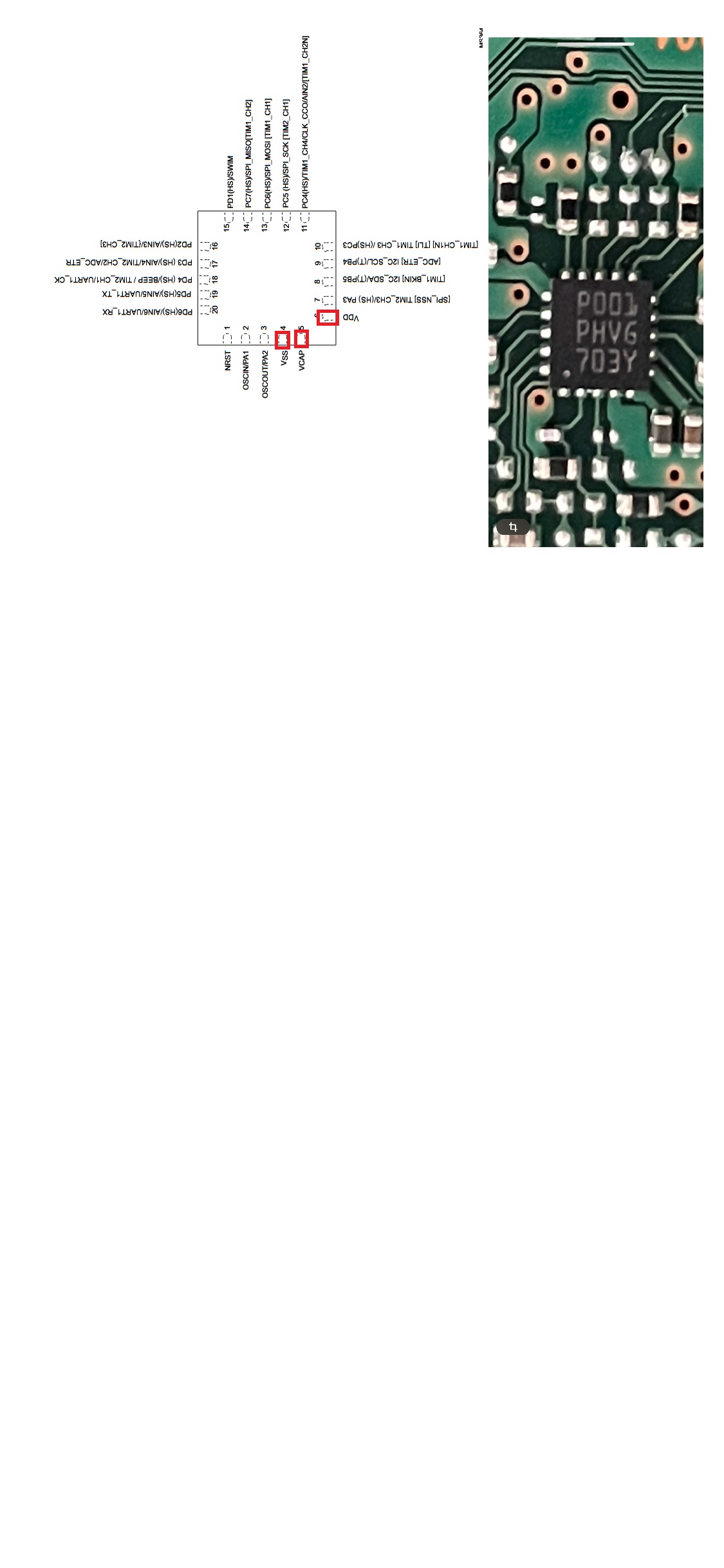
P05/PWM/MSTR_CH0 P04/PWM/MSTR_CH1 P11/PWM/CHECK_COGNSTR_CH0 TIM4_CH0/T12/T41/CH0_SPECS TIM4_CH1/T13/T42/CH1_PASS ADC_T1/GND/SC/T43/T44 VDD NCAP OSC1 OSC2 OSC3 OSC4 P06/UART/UART1_CK P03/UART/UART2_CK P02/UART/UART1_TX P01/UART/UART1_RX PWM PO03 PHVG 703Y
in „Was ist das für ein IC?“ · Mikrocontroller und Digitale Elektronik · · Fotos
-
Bild
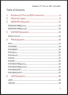
Inhaltsverzeichnis eines Dokuments über Raspberry Pi Pico SCPI
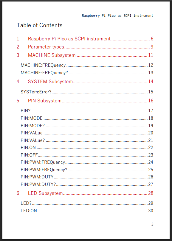
Subsystem 17 PIN? 17 PIN:MODE 18 PIN:MODE? 19 PIN:VALue 20 PIN:VALue? 21 PIN:ON 22 PIN:OFF 23 PIN:PWM:FREquency 24 PIN:PWM:FREquency? 25 PIN:PWM:DUTY 26 PIN:PWM:DUTY? 27 6 LED Subsystem 28 LED? 29 LED:ON 30 3
in „Skyworks kauft Qorvo, Neues von Nexperia und andere Lustigkeiten“ · Mikrocontroller und Digitale Elektronik · · Screenshots
-
Datei
SHIFTOUT_Test.bas
.3 = Input Config Portb = Output Clockeingang Alias Pinc.3 Bitausgabe Alias Pinc.4 Config Timer1 = Pwm , Pwm = 8 , Compare A Pwm = Clear Up , Compare B Pwm = Clear Down , Prescale = 64 Dim Bitzahl As Byte Compare1a = 200 Do Bitzahl = 137 Shiftout Bitausgabe , Clockeingang , Bitzahl , 0 Wait 1 Toggle
in „SHIFTOUT- Befehl in Bascom geht nicht“ · Mikrocontroller und Digitale Elektronik ·
-
PDF
s32k-belegung.pdf
RX1 PTC8 CAN-H PTA7 CAN-L SCL PTA3 PTB0 AIN2 SDA PTA2 PTB1 AIN3 AIN0 PTA0 PTC2 RX0 AIN1 PTA1 PTC1 PWM1 PTC5 (SWDIO) PTA4 PTC3 TX0 PWM3 PTD1 PTB4 MOSI0 PWM2 PTD0 PTB5 CS0 PTE11 PTD15 SCK0 (PWM0) PTE10 PTD16 MISO0 Reset SWD VCC
-
Datei
LCD_test.asm
mehr ;als 35ns hat !!! out MCUCR, temp ldi temp, 10 out OCR1AL, temp ldi temp, 128 out OCR1BL, temp ;PWM: 50% Duty Cycle ldi temp, (1<<COM1B1)|(1<<COM1B0)|(1<<WGM10) ;Enable PWM (Kontrast) out TCCR1A, temp ldi temp, (1<<CS10) ;31,25kHz PWM Frequenz out TCCR1B, temp ldi temp, Reload ;Timer Reloadwert out
in „Grafikfähiger LCD Controller für 320x240 LCD mit 4 Graustufen“ · Projekte & Code ·
-
Datei
Firmware_v1.3.c
########################################################################### { static unsigned char pwm_counter = 0; pwm_counter++; if(pwm_counter == 255) { pwm_counter = 0; } if(dmx_lost<DMX_LOST_TIMEOUT) { dmx_lost++; } } //############################################################################
in „DMX steuerbaren RGB LED PAR oder Pinnspot selber bauen“ · Mikrocontroller und Digitale Elektronik ·
-
PDF
iAQ-2000_interface_V33_high_I2C_12_09.pdf
This document describes the readout of the iAQ-2000 sensor module with I C, RS232 TTL, analog and PWM interface. 2 Chapter 1: I C Chapter 2: PWM Chapter 3: RS232 TTL Chapter 4: Analog output 0...5V During the first 6 hours of continuous operation (burn-in) the module will display 450ppm, 2.5VDC, 50%
in „Geruchssensor - Air Wick Fresh Matic“ · Mikrocontroller und Digitale Elektronik ·
-
Bild
Tabelle Timer Waveform Generation Mode
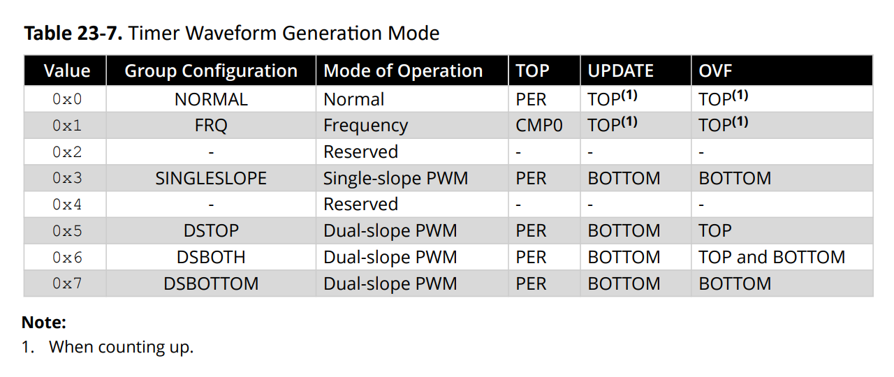
PER TOP(1) TOP(1) 0x1 FRQ Frequency CMP0 TOP(1) TOP(1) 0x2 - Reserved - 0x3 SINGLESLOPE Single-slope PWM PER BOTTOM BOTTOM 0x4 - Reserved - 0x5 DSTOP Dual-slope PWM PER BOTTOM TOP 0x6 DSBOTH Dual-slope PWM PER BOTTOM TOP and BOTTOM 0x7 DSBOTTOM Dual-slope PWM PER BOTTOM BOTTOM Note: 1. When counting up
in „ATmega Timer CTC ASM“ · Mikrocontroller und Digitale Elektronik · · Screenshots
-
Bild
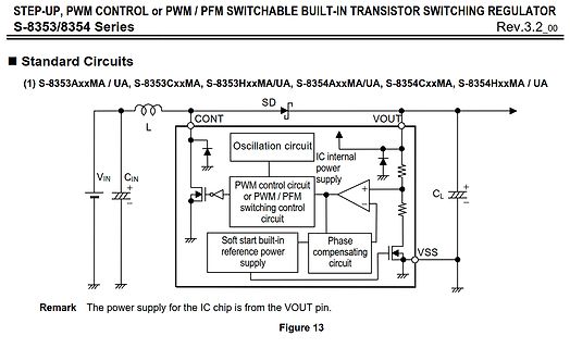
Schaltplan eines Step-Up-Reglers
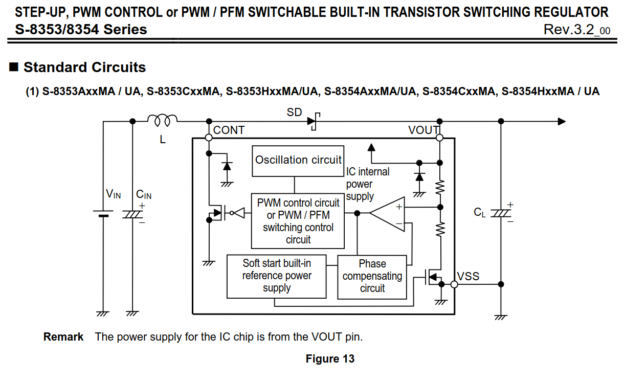
STEP-UP, PWM CONTROL or PWM / PFM SWITCHABLE BUILT-IN TRANSISTOR SWITCHING REGULATOR S-8353/8354 Series Rev.3.2_00 Standard Circuits (1) S-8353AxxMA / UA, S-8353CxxMA, S-8353HxxMA/UA, S-8354AxxMA/UA, S-8354CxxMA, S-8354HxxMA / UA SD L CONT VIN CIN VOUT CL VSS Oscillation circuit IC internal power supply PWM control circuit or PWM / PFM switching control circuit Soft start built-in reference power supply Phase compensating circuit Remark The power supply for the IC chip is from the VOUT pin. Figure 13
in „Suche bauteilbezeichnung SOT23-3 Beschriftung H??Fb“ · Analoge Elektronik und Schaltungstechnik · · Schaltpläne
-
Bild
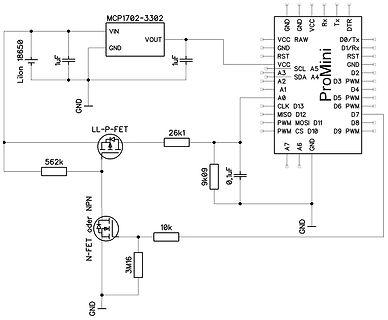
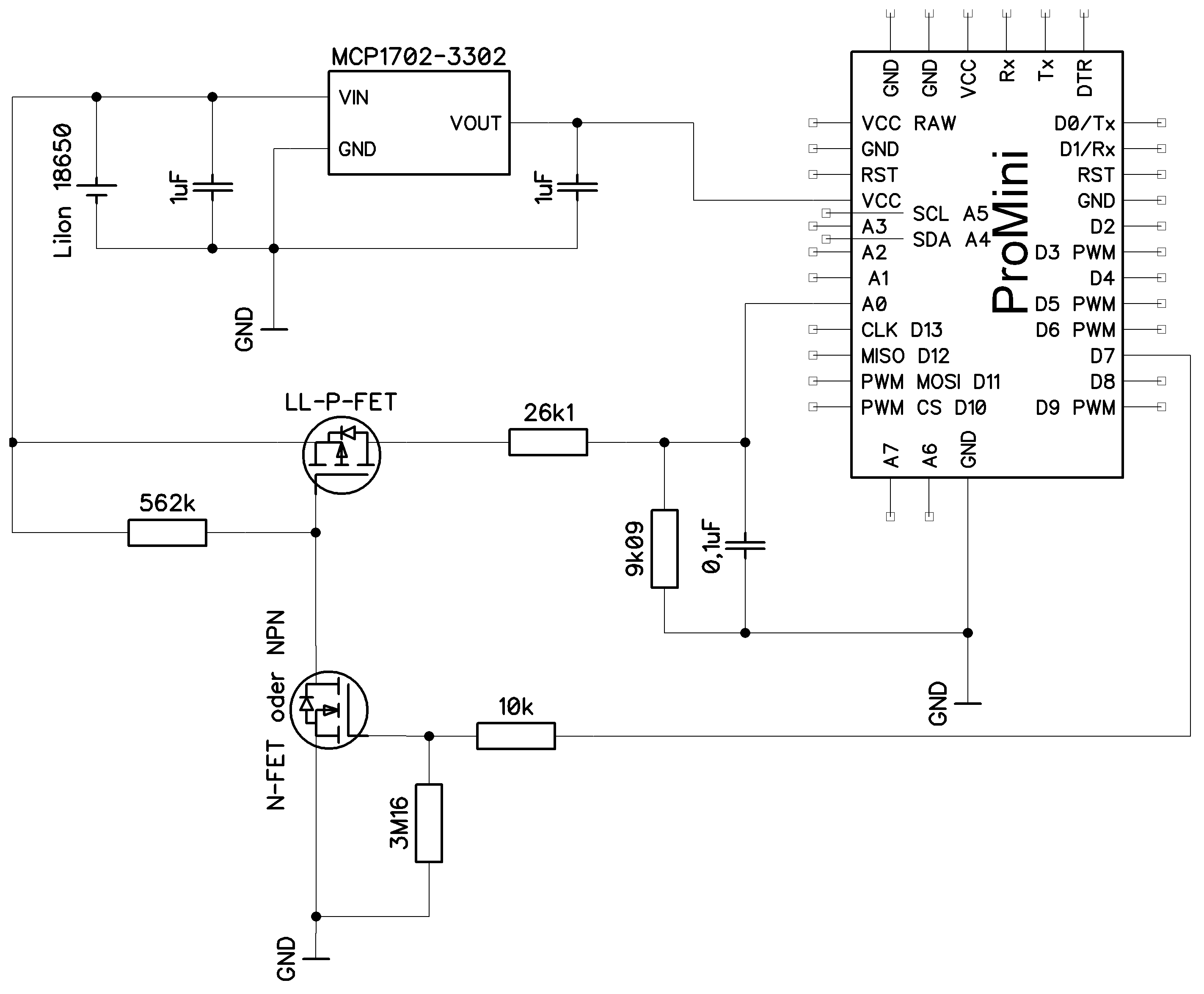
Schaltplan mit Pro Mini, MCP1702-3302 und MOSFETs
18650, 1uF, MCP1702-3302, VIN, VOUT, GND, 1uF, Pro Mini, GND, VCC, RAW, D0/Tx, D1/Rx, RST, GND, D2, D3 PWM, D4, D5 PWM, D6 PWM, D7, D8, D9 PWM, CS, D10, MOSI, D11, MISO, D12, CLK, D13, SDA, A4, A5, SCL, A3, A2, A1, VCC, A0, A7, A6, GND, LL-P-FET, 26k1, 562k, 9k09, 0,1uF, N-FET oder NPN, 10k, 3M16, GND
in „Stromsparende Schaltung Klimalogger auf Basis Rasp Pi Pico“ · Mikrocontroller und Digitale Elektronik · · Schaltpläne
-
Bild
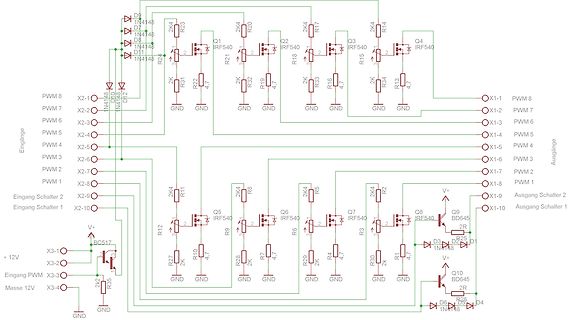
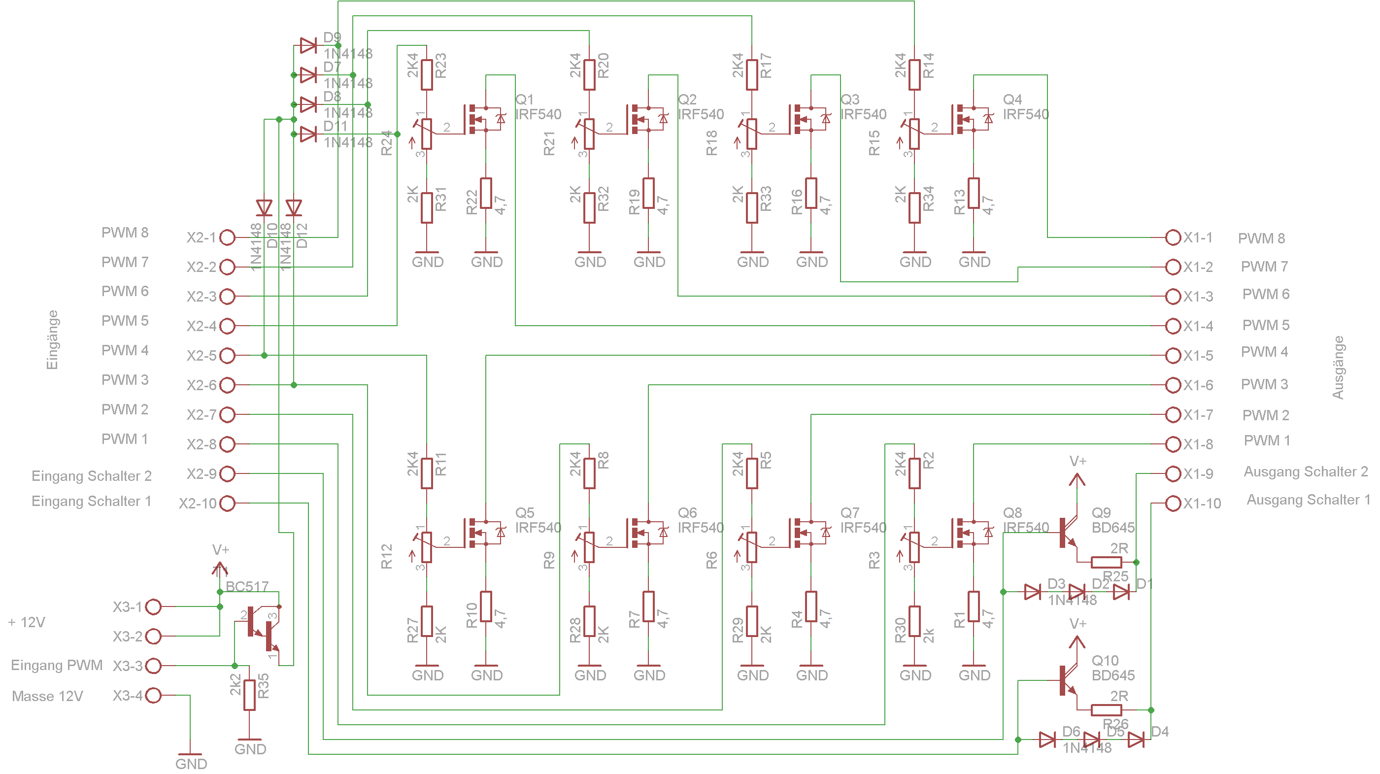
Schaltplan einer MOSFET-Leistungstreiberstufe
Eingänge PWM 8 bis PWM 1, X2-1 bis X2-10, Ausgang PWM 8 bis PWM 1, X1-1 bis X1-7, Eingang Schalter 2, Eingang Schalter 1, Ausgang Schalter 2, Ausgang Schalter 1, X3-1 bis X3-4, +12V, Masse 12V, GND, V+, Q1 IRF540
in „LED mit Konstanzstrom steuern“ · Analoge Elektronik und Schaltungstechnik · · Schaltpläne
-
Bild
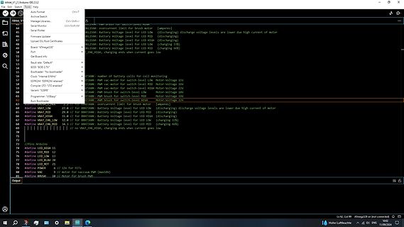
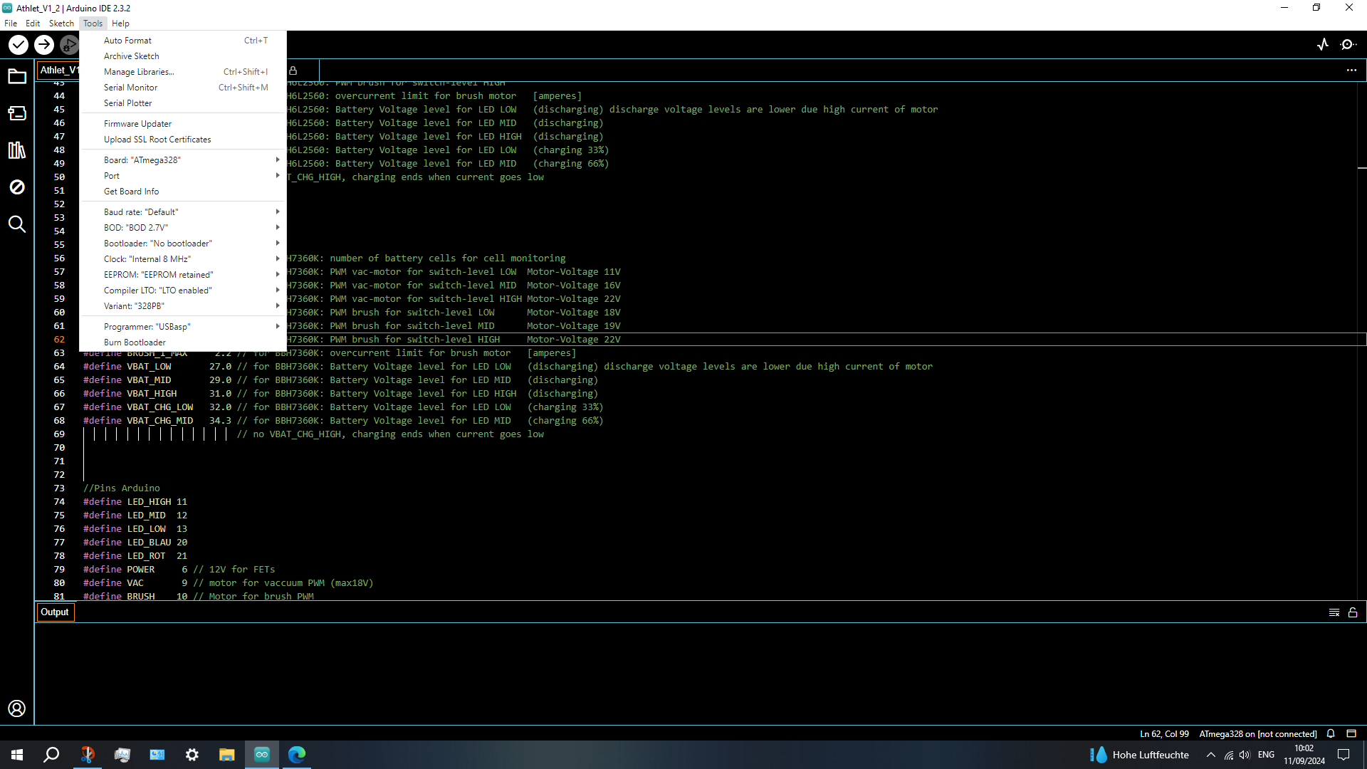
Code-Ausschnitt in der Arduino IDE
Arduino IDE 2.3.2 #define BRUSH_PWM 7360K: PWM brush for switch-low MID Motor-Voltage 22V #define LED_LOW 31 // LED LOW #define LED_MID 12 // LED MID #define LED_HIGH 11 // LED HIGH #define LED_BLAU 31 // LED BLAU #define VBAT_LOW 32
in „Bosch Athlet 25,2 V Akku 7 Stück Tauschen“ · Analoge Elektronik und Schaltungstechnik · · Screenshots
-
Bild
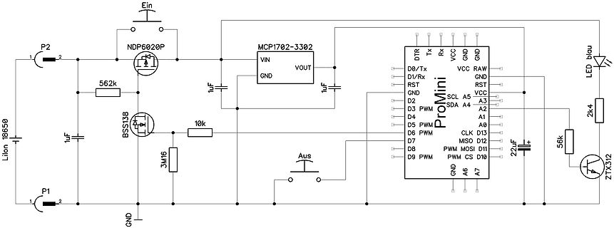
Schaltplan mit ProMini Mikrocontroller und LED-Steuerung
D0/Tx, Tx, Rx, VCC, RAW, GND, RST, VCC, SCL, A5, A3, D1/Rx, A4, A2, GND, A0, RST, D2, SDA, A1, D3, PWM, D4, A0, D5, PWM, D6, PWM, D7, D8, D9, PWM, CS, D10, MISO, D11, MOSI, D12, CLK, D13, A6, A7, LED blau, 2k4, 56k, ZTX312, 22uF, Aus, 3M16, P1, Liion 18650, GND
in „Arduino Nano, P-MOSFET & DC-DC StepUp für BobbyCar LEDs“ · Mikrocontroller und Digitale Elektronik · · Schaltpläne
-
Bild
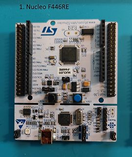
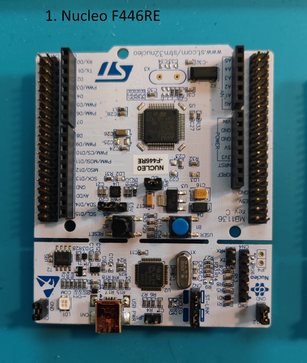
Nucleo F446RE Mikrocontroller-Entwicklungsboard
1. Nucleo F446RE ST RX/D0 TX/D1 D2 PWM/D3 D4 PWM/D5 D6 PWM/D7 D8 PWM/D9 MIS0/D10 SCK/D13 SCL/D14 SCL/D15 RESET AVDD GND C21 C22 U4 LD2 L2 C23 C24 C25 C26 C27 C28 C29 C32 U5 C35 C36 NUCLEO-F446RE ST-LINK USB JP1 SWD ST-LINK MB136 CN4 CN2
in „[V] Sammlung diverser Entwicklungsboards“ · Markt · · Platinenfotos
-
Datei
led_dimmen.bas
'Hardware PWM fürs LED dimmen mit Timer 1 $regfile = "m32def.dat" $framesize = 32 $swstack = 32 $hwstack = 32 $crystal = 8000000 Dim A As Integer Config Pind.5 = Output Config Timer1 = Pwm , Pwm = 8 , Compare A Pwm
in „PWM Versuche mit Bascom“ · Mikrocontroller und Digitale Elektronik ·
-
Datei
Led_funktionen.h
(void); void Led_Weiss_Aus(void); void Led_Blau_An(void); void Led_Weiss_Aus(void); void Led_Weiss_Pwm(uint16_t); void Led_Blau_Pwm(uint16_t); void Led_Weiss_An() { Led_Weiss = 0; } void Led_Blau_An() { Led_Blau = 0; } void Led_Weiss_Aus() { Led_Weiss = 1023; } void Led_Blau_Aus() { Led_Blau = 1023; } void Led_Weiss_Pwm(uint16_t helligkeit) { Led_Weiss = 1023 - helligkeit; } void Led_Blau_Pwm(uint16_t helligkeit) { Led_Blau = 1023 - helligkeit; } #endif // LED_FUNKTIONEN_H_INCLUDED
in „RS232 gibt kein Signal aus“ · Mikrocontroller und Digitale Elektronik ·
-
Datei
RGB-main.c
definieren #include <avr/interrupt.h> //Signal definieren //Funktionsprototypen void Timerinit(void); void PWM(void); //globale Variablen volatile char zaehler = 0; volatile char PWM1 = 100; int main(void) { cli(); Timerinit(); DDRB=0xFF; sei(); while(1) { if (zaehler <= PWM1) { PORTB &= ~(1<<PB0); } else { PORTB = (1<<PB0); } } } SIGNAL (SIG_OVERFLOW0) { zaehler++; if (zaehler == 255) {PWM1++;} } void Timerinit() { TCCR0 = (1<<CS00); TIMSK = (1<<TOIE0); }
in „Mal wieder 'ne Software PWM Frage“ · Mikrocontroller und Digitale Elektronik ·
-
PDF
Sharp_LQ065T5AR01.pdf
phase with VBS. If CLKC="Lo", this terminal will be external vertical sync. input terminal. 【Note5-4】 PWM signal is used for the PWM dimming frequency and it is possible to control the PWM signal dimming by combining both HSY and PWM signal. But, please use this PWM signal just in case of inputting standard
in „Monitor Travel Pilot DX-V“ · Mikrocontroller und Digitale Elektronik ·
-
PDF
EM6580.pdf
defined by the counter length selection BitSel[1:0] (see chapter 6.3). 8.4 Pulse Width Modulation (PWM) The PWM generator uses the behavior of the Compare function (see above) so EnComp must be set to activate the PWM function.. At each Roll Over or Compare Match the PWM state - which is output on port
in „Was ist aus dem Thread der MeteoData geworden?“ · Mikrocontroller und Digitale Elektronik ·
-
Datei
PPS5330_V15.c
1<<ADC_AD2); DDRB &= ~(1<<ADC_ADW); // extern INT0 for Meassurement DDRB |= (1<<PIN1); // PB1 OC1A PWM Voltage DDRB |= (1<<PIN2); // PB2 OC1B PWM Ampere DDRC |= (1<<PIN3); // Key "Standby" DDRD &= ~(1<<PIN0); // Regler DDRD &= ~(1<<PIN2); // Encoder Pin A DDRD &= ~(1<<PIN3); // Encoder Pin B DDRC &=
in „PPS5330 Labor-Netzteil hack“ · Mikrocontroller und Digitale Elektronik ·
-
PDF
AN-694_Motor_DC_PWM.pdf
and the direction of rotation depends on whether the duty cycle is greater than or less than 50%. PWM Dir Brake Active Output Drivers H H L A1, B2 One disadvantage of Locked Anti-phase control with the LMD18200 is that the current sense output is discontinuous H L L A2, B1 as shown in Figure 9. This
in „DC Motor Controller mit AtMega328 PWM + current limiting“ · Mikrocontroller und Digitale Elektronik ·
-
Datei
led_dimmen.bas
'Hardware PWM fürs LED dimmen mit Timer 1 $regfile = "m32def.dat" $framesize = 32 $swstack = 32 $hwstack = 32 $crystal = 8000000 Dim A As Integer Config Pind.5 = Output Config Timer1 = Pwm , Pwm = 8 , Compare A Pwm
in „PWM Versuche mit Bascom“ · Mikrocontroller und Digitale Elektronik ·
-
Datei
nixie-in13-1.bas
regfile = "m8def.dat" $crystal = 3685400 $hwstack = 64 $swstack = 64 $framesize = 64 Config Timer1 = Pwm , Pwm = 8 , Compare A Pwm = Clear Up , Compare B Pwm = Clear Up , Prescale = 1 Compare1a = 75 Compare1b = 255 Dim A As Byte Dim B As Byte Do Compare1b = 180 Wait 2 For A = 1 To 5 For B = 10 To 200 Step
in „Experiment mit IN9-Nixie“ · Mikrocontroller und Digitale Elektronik ·
-
Datei
Servo_Code.txt
$regfile = "m8def.dat" $crystal = 1000000 Config Timer1 = Pwm , Pwm = 10 , Compare A Pwm = Clear Down , Prescale = 8 Enable Timer1 Start Timer1 'Config Pinb.1 = Output 'Config Pinc.0 = Input Dim L As Single Dim S As Single Dim Pw As Word Config Adc = Single ,
in „Servo mit Pwm und Poti ansteuern, wo ist mein Fehler?“ · Mikrocontroller und Digitale Elektronik ·
-
PDF
2021_11_09_Projektierungshandbuch_de.pdf
Anschlusskabel PWM-Signal (3 x 0,75 mm , 1,5 m) (PWM – 2 x 0,5 mm , 2 m) L1 – Schwarze / braune Litze Braune Litze – PWM GND N – Blaue Litze Blaue Litze – PWM Eingangssignal PE – Gelb/grüne Litze Last- und Steuerkabel
-
PDF
mic23050.pdf
MIC23050 4MHz PWM Buck Regulator with HyperLight Load™ Switching Scheme General Description Features The Micrel MIC23050 is a high-efficiency, 600mA, PWM, • Input voltage: 2.7V to 5.5V HyperLight Load™ synchronous buck
in „LDO und Step-Down-Converter parallel“ · Analoge Elektronik und Schaltungstechnik ·
-
PDF
LGT8F328P.pdf
PWM waveform. Fast PWM The mode differs from other PWM modes in that it is a one-way operation. The counter is returned from the BOTTOM to the TOP BOTTOM recounting. When the count value TCNT3 reaches TOP
in „Neue 8-Bit Tinys vorgestellt: 417/814/816/817“ · Mikrocontroller und Digitale Elektronik ·
-
Bild
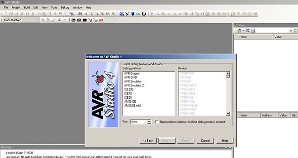
Startbildschirm der Software AVR Studio 4
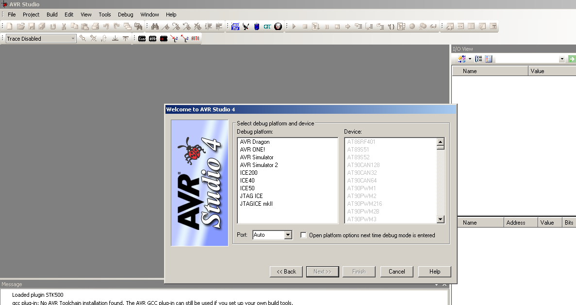
AVR Simulator AT89S52 AVR Simulator 2 AT90CAN128 ICE200 AT90CAN32 ICE40 AT90CAN64 ICE50 JTAG ICE AT90PWM1 JTAGICE mkII AT90PWM216 AT90PWM28 AT90PWM3 Port: Auto Open platform options next time debug mode is entered Name Address Value Bits Message Loaded plugin STK500 occ plug-in: No AVR Toolchain installation
in „AT89S52 mit AVRisp MKII auslesen / flashen“ · Mikrocontroller und Digitale Elektronik · · Screenshots
-
Bild
Screenshot einer Software zur Arduino-Programmierung und Debugging
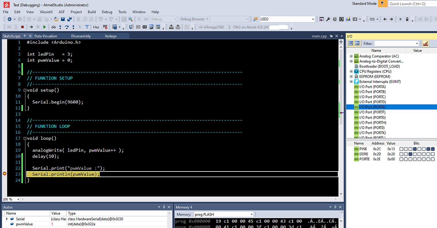
Build Debug Tools Window Help sketch.cpp LED2 main.cpp I/O Filter: Name Value int ledPin = 3; int pwmValue = 0; // // // FUNKTION SETUP // void setup() { Serial.begin(9600); } // // // FUNKTION LOOP // void loop() { analogWrite(ledPin, pwmValue++); delay(10); Serial.print("pwmValue : "); Serial.println(pwmValue); } Autos Name Value Type Memory prog FLASH Memory prog 0x000000 19 c1 00 45 c1 00 43 c1 00 .Á..ÉÁ..cÁ. 0x000008 00 41 c1 00 00 3f c1 00 3d c1 .á Áá 26
in „Mit dem ATMEL STUDIO 7 klarkommen“ · Mikrocontroller und Digitale Elektronik · · Screenshots
-
Datei
Mardenschreck.asm
AT15 Stairs light based on Nlite2 ; night light switch using LDR to sense light ; and Marderschreck pwm frequency sweep ultrasonic output 20-40kHz ; ; night light switch reading LDR on ADC3, fixed on-time ; light turns off after on-time elapsed or day ; light threshhold is calculated ; DayLow PB2 shows
in „Marderschreck Softwareproblem“ · Mikrocontroller und Digitale Elektronik ·
-
Datei
Mardenschreck.asm
AT15 Stairs light based on Nlite2 ; night light switch using LDR to sense light ; and Marderschreck pwm frequency sweep ultrasonic output 20-40kHz ; ; night light switch reading LDR on ADC3, fixed on-time ; light turns off after on-time elapsed or day ; light threshhold is calculated ; DayLow PB2 shows
in „Marderschreck Softwareproblem“ · Mikrocontroller und Digitale Elektronik ·
-
Datei
zusammen_fade_manuell.asm
equ key_port = PORTD .equ key_ddr = DDRD .equ led_port = PORTB .equ led_ddr = DDRB //Zuweisungen für PWM .def temp = r17 .def PWMCount = r19 .def ocr_r = r20 ; Helligkeitswerte der LED R/G/B .def ocr_g = r21 .def ocr_b = r22 .def level_r = r23 .def level_b = r24 .def level_g = r25 .def fadestatus= r26
in „Mega8 Assembler RGB Fader“ · Mikrocontroller und Digitale Elektronik ·
-
Datei
dtmf_geb_m8a.asm
DTMF Generator ;* Datum : 16.02.2006 ;* Version : a ;* Target MCU : Any AVR with SRAM, 8 I/O pins and PWM ;* ;* This Application note describes how to generate DTMF tones using a single ;* 8 bit PWM output. ;* ;*************************************************************************** .nolist ; ## .include
in „DTMF AVR314 nach mega8“ · Mikrocontroller und Digitale Elektronik ·
-
PDF
Amilo_Core_Erzeugung.pdf
PC108 PC111 1 2 PVID1 VID3 PWM4 VCC +5V LGATE 2.2_0603 820u/2.5V_8*13 820u/2.5V_8*13 Z2625 PVID0 1 23 PR148 ISL6207 4 G 4 G 4 G OS-SEPC OS-SEPC VID2 ISEN4 549_1 PD22 Z2624 + 2 22 Z2609 PC140 PR146 S S S SK34A PC112 PC107 VID1 ISEN1
in „Laptop geht nicht an: MOSFET 4C06N?“ · Analoge Elektronik und Schaltungstechnik ·
-
PDF
recommended.pdf
to an external clock signal with CMOS level: SYNC = HIGH: Low-noise mode enabled, fixed frequency PWM operation is forced SYNC = LOW (GND): Power save mode enabled, PFM/PWM Mode enabled VIN 2, 3 I Supply voltage input (power stage) VINA 8 I Supply voltage input (support circuits) PowerPAD™ Connect to
in „Kurz vorm Verzweifeln“ · Analoge Elektronik und Schaltungstechnik ·
-
PDF
TPS6211.pdf
to an external clock signal with CMOS level: SYNC = HIGH: Low-noise mode enabled, fixed frequency PWM operation is forced SYNC = LOW (GND): Power save mode enabled, PFM/PWM Mode enabled VIN 2, 3 I Supply voltage input (power stage) VINA 8 I Supply voltage input (support circuits) PowerPAD™ Connect to
in „DC DC Wandler Pins“ · Analoge Elektronik und Schaltungstechnik ·
-
PDF
TPS6211.pdf
to an external clock signal with CMOS level: SYNC = HIGH: Low-noise mode enabled, fixed frequency PWM operation is forced SYNC = LOW (GND): Power save mode enabled, PFM/PWM Mode enabled VIN 2, 3 I Supply voltage input (power stage) VINA 8 I Supply voltage input (support circuits) PowerPAD™ Connect to
-
PDF
TPS6211.pdf
to an external clock signal with CMOS level: SYNC = HIGH: Low-noise mode enabled, fixed frequency PWM operation is forced SYNC = LOW (GND): Power save mode enabled, PFM/PWM Mode enabled VIN 2, 3 I Supply voltage input (power stage) VINA 8 I Supply voltage input (support circuits) PowerPAD™ Connect to
in „QFN Gehäuse.“ · Analoge Elektronik und Schaltungstechnik ·
-
PDF
TPS6211.pdf
to an external clock signal with CMOS level: SYNC = HIGH: Low-noise mode enabled, fixed frequency PWM operation is forced SYNC = LOW (GND): Power save mode enabled, PFM/PWM Mode enabled VIN 2, 3 I Supply voltage input (power stage) VINA 8 I Supply voltage input (support circuits) PowerPAD™ Connect to
in „Trennung von analoger und digitaler Spannung“ · Analoge Elektronik und Schaltungstechnik ·
-
Datei
rgbfade.c
; move on to the next state2++; state2%=6; } } void mode1(void){ rainbowfade(1); //Fade 1 step per PWM Cycle } void mode2(void){ state++; if (state%128==0){//Every 128 PWM cycles //Save old colors char r=red; char g=green; char b=blue; //Rotate colors red=g; green=b; blue=r; } } void mode3(void){ state++; if (state%128==0){ //Every 128 PWM Cycles rainbowfade(255); //Skip to the next color } } void mode0(void); #define NUM_MODES 4 //Array of mode function pointers typedef void(*modefn)(void); modefn modefns[NUM_MODES]={ mode0, mode1, mode2
in „Attiny 13 RGB Steuerung“ · Mikrocontroller und Digitale Elektronik ·
-
Datei
hardwaredef.h
VERT_BRAKE_OFF PORTC &= ~(1<<VERT_STOP) #define VERT_BRAKE_ON PORTC |= (1<<VERT_STOP) #define VERT_PWM PD4 #define VERT_SPEED OCR1B // others #define VERT_MAXPOS 20000 // 0,04225 mm / Tick + 2,553mm / DVD -> 60.5 Tick / DVD #define DVD_MACHINE_FACTOR 60.5 //-------------------------------------------
in „ATMega32 Absturz bei Zeicheneingang“ · Mikrocontroller und Digitale Elektronik ·
-
Bild
GitHub Release Notes für Software-Patch
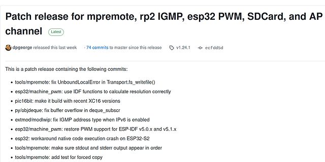
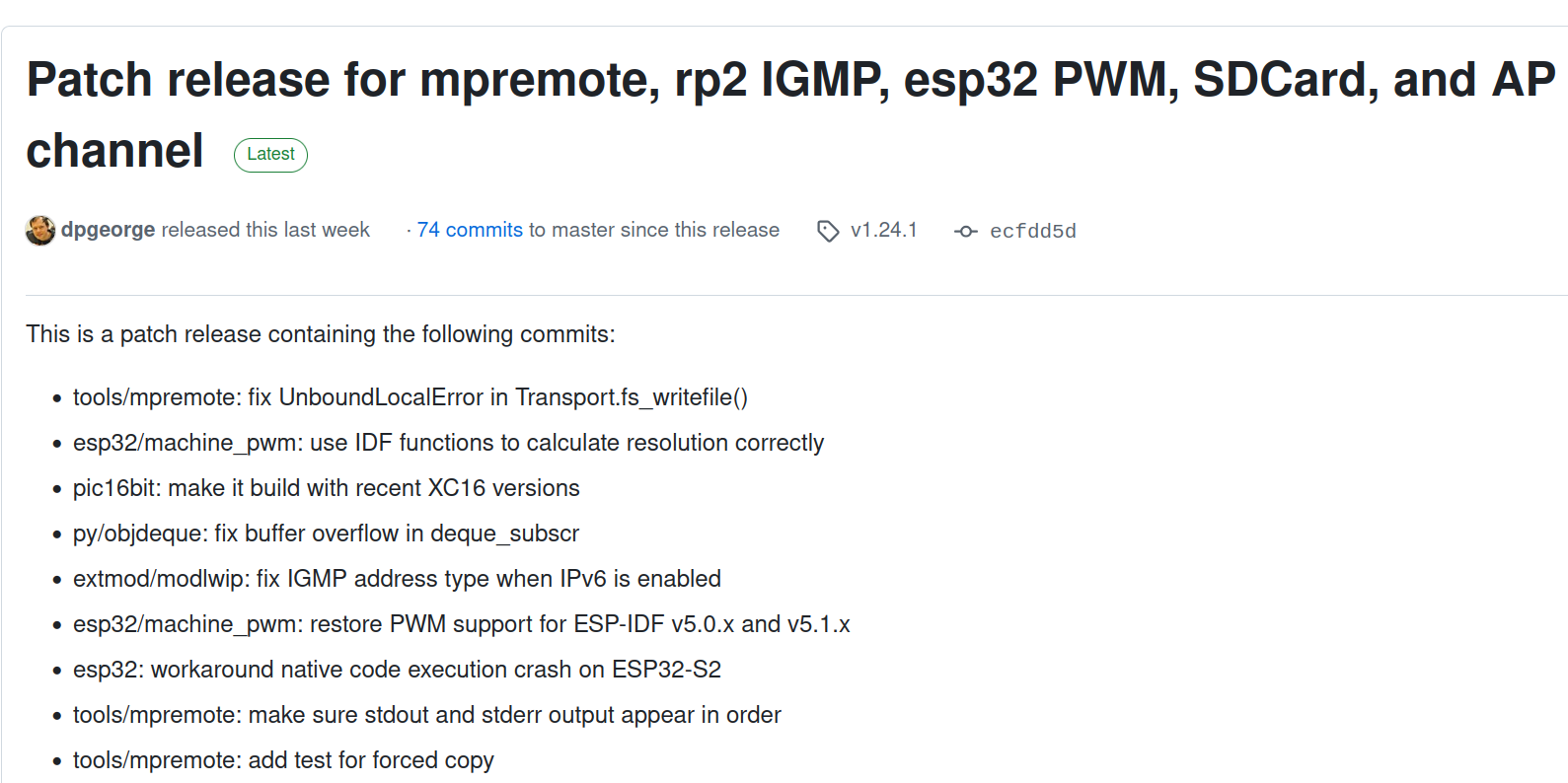
Patch release for mpremote, rp2 IGMP, esp32 PWM, SDCard, and AP channel Latest dpgeorge released this last week · 74 commits to master since this release · v1.24.1 · ecfdd5d This is a patch release containing the following commits: • tools/mpremote

in „Eclipse-Entwicklerumfrage, MicroPython und Arduino-Cores auf Basis von Zephyr“ · Mikrocontroller und Digitale Elektronik · · Screenshots