1.32 V atFI = 50 mA) V F - F = 5 mA voltage Maximum 1.5 V Typical 0.035 Ω 0.08 Ω F = 5 mA R on A L = Max. Maximum 0.08 Ω 0.12 Ω Within 1 s Typical 0.018 Ω 0.04 Ω F = 5 mA t On resistance R on B L = Max. t Maximum 0.04 Ω 0.06 Ω Within 1 s u O Typical 0.01 Ω 0.02 Ω F = 5 mA R on C L = Max. Maximum 0.02 Ω
generated when the counter is equal to TOP. If TOP is updated to a value lower than count upon reaching MAX, the counter restarts from BOTTOM. Figure 21-3. Periodic Interrupt Mode MAX and Event) Request TOP CNT BOTTOM TOP changed to CNT set to BOTTOM a value lower than CNT 21.3.3.1.2 Time-Out Check Mode In
Transfer Capacitance ––– 52 ––– pF ƒ = 1.0MHz rss Avalanche Characteristics Symbol Parameter Typ. Max. Units EAS Single Pulse Avalanche Energy ––– 213 mJ AR Avalanche Current ––– 62 A Diode Characteristics Symbol Parameter Min. Typ. Max. Units Conditions S Continuous Source Current MOSFET symbol D –
Pout is 200W The typical junction-to-case thermal resistance of (MusicPower). the TDA7294S is 1 oC/W (max=1.5 C/W). To avoid that, in worst case conditions, the chip temperature exceedes 150 oC, the thermal resis- APPLICATION NOTE: (ref. fig.7) tance of the heatsink must be 0.038 C/W (@ max ambient temperature
DELAY Switch Off Delay Time 300 ns Internal Time Control Section T OFF_MIN Minimum OFF Time 3 us T OFF_MAX Maximum OFF Time 340 us T ON_MAX Maximum On Time 53 us MOSFET Section Static Drain-source RDSON Vcc=7V/Id=0.5A 12.8 16 ohm On-resistance Drain-Source Breakdown V DS_BD Vgs=0V/Id=250uA 500 V Voltage
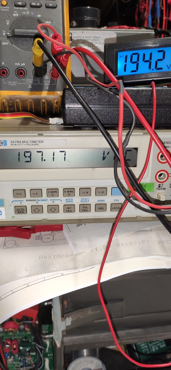
mV Ω mA OFF V mA µA 10A MAX FUSED CAT III 1000V 194.2 V 3478A MULTIMETER HEWLETT PACKARD 197.17 V RANGE/N. DIGIT 2 WIRE Ω 4 WIRE Ω AUTO ZERO TEST/RESET ADRS CAL SGL TRIG SRQ LOCAL AUTO MAN INT TRIG Bestückplan 04:02:97
175W Aufnahmeleistung" angegeben, erwarten würde ich bei einem einwandfreien Netztrafo im Leerlauf max. 250mA bei 230V Einspeisung... Was ist Dein Messergebnis?
33k 3) +8.94V über R200 / 62k 4) +15V über R225 10k in Reihe mit D101 24V-Z-Diode 5) 45,5V über R197 in Reihe mit D120 und D119 ("71V over") 6) +-66V über R198, R199 als virtuelle Masse jetzt musst du die Spannungen abklappern, irgendeine wird falsch sein, R198 oder R199 könnten auch schuld sein
PARAMETER SYMBOL UNIT MIN MAX (1) VCC (min) to /CS Low tVSL 20 µs (1) Time Delay Before Write Instruction tPUW 5 ms (1) Write Inhibit Threshold Voltage V WI 1.0 2.0 V Note: 1. These parameters are characterized only. VCC VCC (max
Byrearrangingthisformula,aminimumvalueforMcanbe V IN(LOW) found: V = D1 and D2 forward voltage V IN(MAX) F M (MIN)= V IN(LOW)= minimuminput voltage V M V IN(MAX) − VSNUB For the circuit shown, with V = 0.6V, V = 20V: F IN(LOW) VM= maximumLT1070 switch voltage VIN(MAX)= maximuminput voltage ( . + 5)( +
VD-01 VD-02 VD-03 VD-04 Max.cooling area 80litres 30 litres 170 litres 130 litres contentat 35 mm PU insulation: Max.cooling area 100 litres 50 litres 200litres 170 litres contentat 50 mm PU insulation: Power consumption: 35W
Einschaltberechtigung 2 Nummer des Schaltbefehls (max. 8) ändern. Werk- seinstellung: Schaltbefehl 1 D7001_581_01_DE.fm Seite 2 Dienstag, 14. Oktober 2008 1:31 13 Schaltkontakt Technische Daten Die ersten beiden Parameter können nicht einge- Versorgungsspannung
50 J0(jx)= I 0x) (Dwight p195, 813.1) J1(jx)= jI 1x) (Dwight p195, 813.2) H (jx)=−j K (x)2 (Dwight p197, 817.2) 0 π 0 (1) 2 H 1jx)=− K (xπ 1 (Dwight p197, 817.5) Where I nnd K arn modified Bessel functions of the first and second kind. Thus, noting the 2 cancellations that occur, and that j =-1 : (1)
coordinates exceed the maximum pattern size, the repeat, cramp or border color option is selected. S (max. ±8192) ) 9 8 max. 4096 pixels . a ( T Origin e p Texture 6 pattern 0 x a m 8.1.3 Frame buffer For drawing, the following area must be assigned to the Graphics Memory. The frame size (count of pixels
UMICH (J H-H 4) REA RVIEW R 4 1 3 1 E X T E R N A L V I EW R 4131E X T171 1-A ) 0 0 LCL RMT —WRITE 0 - MAX STORE ~VIEW RECALL SAVE —SHIFT INPUT ATTENUATOR - — SWEEP VIDEO I0kHz- .5GHz ( r n i r l R4131A SPECTRUM ANALYZER FREERUN 0 TDE/DIV FLTR +20dBMAX S T A R T H 25VDC MAX P E R /RESET LINE OFF ON PHONE
Meine inzwischen fast 20 Jahre alten "Max!"-Ventile funzen wie am ersten Tag. Jeden Sonntag morgen gegen 3 Uhr fahren die einmal ganz auf und ganz zu, eben um das Festrotten zu verhindern. Als "Basis-Temperatur" habe ich überall 17 Grad
4.2, VDD = 1.8V, VDDIO = 1.8V, T =25°C, unless otAerwise noted. PARAMETERS CONDITIONS MIN TYPICAL MAX UNITS NOTES I C TIMING I C FAST-MODE fSCLSCL Clock Frequency 400 kHz 1, 2 tHD.STA, (Repeated) START Condition Hold 0.6 µs 1, 2 Time tLOW , SCL Low Period 1.3 µs 1, 2 tHIGH, SCL High Period 0.6 µs 1,
129.9 137.8 145.7 V 10˚ 10˚ 0046067/H 19/28 LD1117 SERIES SO-8 MECHANICAL DATA mm. inch DIM. MIN. TYP MAX. MIN. TYP. MAX. A 1.35 1.75 0.053 0.069 A1 0.10 0.25 0.04 0.010 A2 1.10 1.65 0.043 0.065 B 0.33 0.51 0.013 0.020 C 0.19 0.25 0.007 0.010 D 4.80 5.00 0.189 0.197 E 3.80 4.00 0.150 0.157 e 1.27 0.050 H 5.80 6.20 0.228 0.244 h 0.25 0.50 0.010 0.020 L 0.40 1.27 0.016 0.050 k 8˚ (max.) ddd 0.1 0.04 0016023/C 20/28 LD1117 SERIES DPAK MECHANICAL DATA mm. inch DIM. MIN. TYP MAX. MIN. TYP. MAX. A 2.2 2.4 0.086 0.094 A1 0.9 1.1 0.035 0.043 A2 0.03 0.23 0.001 0.009 B 0.64 0.9 0.025 0.035
name Pin I/O Description DC features Note number USIM_DATA 15 IO USIM card data 1.8V USIM: - bus V max=0.6V IL V IHn=1.2V V OLx=0.45V V min=1.35V OH 3.0V USIM: V max=1.0V IL V IHn=1.95V V OLx=0.45V V min=2.55V OH USIM_CLK 16 DO USIM card clock 1.8V USIM: - line V OLmax=0.45V V min=1.35V OH 3.0V USIM:
voltage VF IF= 50 mA Maximum 1.5 V IF = 10 mA Typical 0.11 Ω 0.23 Ω 0.7 Ω 2.1 Ω On resistance R on IL=Max. Output Maximum 0.18 Ω 0.34 Ω 1.1 Ω 3.2 Ω Within 1 s on time IF = 0 mA Off state leakage current Maximum — 10 μA VL = Max. Typical 2.46 ms 2.40 ms 1.12 ms 1.65 ms IF = 10 mA IL= 100 mA Maximum 5.0 ms
powerdissipationhasa fixedlimitvalue (P tot max K usuallypresentedformountingbasetemperaturesof25 ˚C. is the maximum d.c. power dissipation below T ). If the mb K At higher temperatures, operating conditions must be transistor is subjected to a mounting-base
1543-650 Actuating Force....................0.8 to 2.4 N Bounce Time ....................45 μsec. max. Switch Function........1 pole push switch Switch Rating.......................24 V/0.01 A without inductive load L ± 0.2 L ± 0.2 Temperature Range......-25 °C to +70 °C (L ± .008) (L ± .008) Switch
.................................... 3. Revise Max t , t RromF15ns to 40ns in Table 11 - 8080-Series MPU Parallel Interface Timing Characteristics .......................................................................................................................................... 4. Revise Max t , t RromF15ns to 40ns in Table 12 – Serial Interface Timing Characteristics.....................d Table 1 - Ordering Information....................................................................
: 0] Operating mode TOP value Update OCR0X moments Set TOV0 at all times 0 Normal 0xFF immediately MAX 1 PCPWM 0xFF TOP BOTTOM 2 CTC OCR0A immediately MAX 3 FPWM 0xFF TOP MAX 4 Keep it - - - 5 PCPWM OCR0A TOP BOTTOM 6 Keep it - - - 7 FPWM OCR0A TOP TOP The following table shows the polarity control of
The maximum allowable continuous power dissipation at any ambient temperature is calculaDed by PTJ(MAX)- Lead Temperature ....................................260C TA/ JA. Exceeding the maximum allowable power dissipation Storage Temperature.............. –65°C to +150C will cause excessive die temperature
CHARACTERISTICS V = 12V, T = +25°C, unless otherwise noted. IN A Parameter Symbol Condition Min Typ Max Units Shutdown Supply Current VEN = 0V 0.3 3.0 µA Supply Current V = 2.0V, V = 1.0V 1.3 1.5 mA EN FB Feedback Voltage V FB 4.75V ≤ VIN≤ 23V 0.900 0.925 0.950 V Feedback Overvoltage Threshold 1.1 V Error
otherwise specified. Table 3.3. GPIO Output Specifications Parameter Symbol Test Condition Min Typ Max Unit RS-485 Active Time After Stop BittACTIVE — 1 — bit time TX Toggle Rate fTXTOG — 15 — Hz RX Toggle Rate fRXTOG — 15 — Hz Clock Output Rate fCLOCK ~158k — 20M Hz Note: 1.Bit-time is calculated as
Condition Pb-Free assembly (see figure at right) -Temperature Min (T ) +150℃ s(min) Pre -Temperature Max(T s(max) +200℃ Heat Reflow condition -Time (Min to Max) (ts) 60-180 secs. tp TP Average ramp up rate (Liquidus Temp Ramp-up Critical Zone 3℃/sec. Max TLto P (TL)to peak) TL L T s(max) to TL- Ramp-up Rate 3℃/sec. Max rS(max) r Ramp-down -Temperature(T L)(Liquidus) +217℃ p Preheat Reflow eS(min) -Temperature(t ) 60-150 secs. T s L 25 time to peak temperatue Peak Temp (T ) p +260(+0/-5)℃ (t 2℃ to peak) Time Time within
and M is milliseconds. tempminmax - Raw Attribute is the disk temperature in Celsius. Info about Min/Max temperature is printed if available. This is the de- fault for Attributes 190 and 194. The recording interval (lifetime, last power cycle, last soft reset) of the min/max values is device specific.
as ambient temperature varies. Wetted contacts Wetted contacts PARAMETER CONDITIONS SYMBOL MIN TYP MAX MIN TYP MAX UNITS Contact Ratings Switching Voltage Max DC/PeakAC Resistive VL - - 500 - - 500 Volts Switching Current Max DC/PeakAC Resistive IL - - 2 - - 2 Amps Carry Current Max DC/PeakAC Resistive
current Typical IIN 6.5 mA VIN= 5 V Typical 0.066 Ω 0.180 Ω 0.64 Ω 2.4 Ω VIN= 5 V On resistance Ron IL= Max. Maximum 0.18 Ω 0.34 Ω 1.1 Ω 3.2 Ω Output Within 1 s on time VIN= 0 V Off state leakage current Maximum leak 10 μA VL = Max. Typical 5.8 ms 4.2 ms 2.7 ms 2.3 ms VIN= 5 V Turn on time* Ton IL= 100 mA
NeoPixelBus-Bibliothek (https://github.com/Makuna/NeoPixelBus) über I2S und DMA angesteuert. Elektret-Module mit MAX4466 und MAX9814 sind vorhanden. Einzelne Elektret-Mikrofonkapseln und NE567D sind im Zulauf. Gibt es noch andere Optionen? Der ADC des ESP8266 scheint ungeeignet zu sein, da er bei aktivem WLAN
scheint aber der zu geringe Eingangspegel der Kapsel gewesen zu sein. Ich habe jetzt stattdessen ein MAX4466-Elektret-Mikrofonmodul (Schaltplan ähnlich https://github.com/adafruit/Adafruit-MAX4466-Electret-Mic-Amplifier-PCBs/blob/master/Adafruit%20MAX4466%20Mic%20Amp.sch) über 1nf an Pin 3 angeschlossen
analoge Platine stammte: > https://audiocreativ.de/index.php?route=product/product&path=59&product_id=197 Ok. Das heisst ich bräuchte noch einen 225VA Trafo mit max 18V AC. Schade das keinen weiteren Angaben zum Modul gemacht werden. Man bräuchte die max Betriebsspannung.
Table 9: Recommended Operating Conditions Symbol Parameter Min Typ Max Unit VDDA, VDD3P3, Voltage applied to power supply pins per power domain2.8 3.3 3.6 V VDD3P3_RTC VDD_SPI (working as 1 — 1.8 3.3 3.6 V input power supply) VDD3P3_RTC_IO 2 — 3.0 3.3 3.6 V VDD3P3_CPU
request->send(request->beginChunkedResponse("application/json",[zeile=0](uint8_t *buffer, size_t maxLen, size_t index) mutable -> size_t { if (maxLen < 50) return RESPONSE_TRY_AGAIN; // Wenn nicht genug platz im Buffer ist, warten wir lieber nochmal. String json_part; if (zeile

 Bild
Bild