-
Datei
irsndconfig.h
------------------------------------------------------------------------------------------------ * PIC C18 section: * * Change hardware pin here: IRSND_PIC_CCP1 = RC2 on PIC 18F2550/18F4550, ... * IRSND_PIC_CCP2 = RC1 on PIC 18F2550/18F4550, ... *------------------------------------------------------
in „IR Signal falsch“ · Mikrocontroller und Digitale Elektronik ·
-
Datei
Ind_Adr_V0_0.lst
Bit IRP aus dem STATUS- 00051 ; Register setzt. 00052 ; Will man auf Speicher in den Bänken 0 und 1 zugreifen muss also IRP 00053 ; gelöscht (=0) sein, will man dagegen auf die Bänke 2 und 3 zugreifen, 00054 ; muss man vorher IRP setzen (=1). 00055 ; 00056 ; DATENBLATTAUSZUG PIC 16F628 00057 ; 4.2
in „PIC16F628 und FSR“ · Mikrocontroller und Digitale Elektronik ·
-
Datei
benchmark.c
// dsPIC@30MIPS = 64.26µs // ATMEGA@16MIPS = 329µs // LPC2103@60MIPS = 23.47µs pa16 = (short*)a; for (i=0; i<128; i++) { *pa16++=0; } // fill 128 16bit words // PIC18@10MIPS = // PIC24@40MIPS = 48.20µs // dsPIC
in „LPC2103 63MIPS?“ · Mikrocontroller und Digitale Elektronik ·
-
 Bild
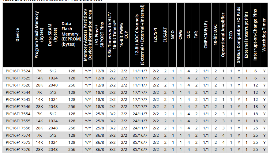
Vergleichstabelle von PIC16F Mikrocontrollern
, Interrupt-on-Change Pins, Watchdog Timer PIC16F17524, 7K, 512, 128, Y/Y, 12/8, 2/2, 2/2, 11/11/7, 2/2, 2, 1, 1, 4, 2, 1/1, 2, 1, 1, Y, 1, 6, Y PIC16F17525, 14K, 1024, 128, Y/Y, 12/8, 2/2, 2/2, 11/11/7, 2/2, 2, 1, 1, 4, 2, 1/1, 2, 1, 1, Y, 1, 6, Y PIC16F17526, 28K, 2048, 256, Y/Y, 12/8, 2/2, 2/2, 11/11/7, 2/2, 2, 1, 1, 4, 2, 1/1, 2, 1, 1, Y, 1, 12, Y PIC16F17544, 7K, 512, 128, Y/Y, 18/8, 2/2, 2/2, 17/17/7, 2/2, 2, 1, 1, 4, 2, 1/1, 2, 1, 1, Y, 1,
in „Neue Bauteile: Zenerdioden, Steckverbinder, PIC16-Nachwuchs und mehr“ · Mikrocontroller und Digitale Elektronik · · Screenshots
-
Datei
irmpconfig.h
1 // JVC >= 10000 ~150 bytes #define IRMP_SUPPORT_NEC16_PROTOCOL 1 // NEC16 >= 10000 ~100 bytes #define IRMP_SUPPORT_NEC42_PROTOCOL 1 // NEC42 >= 10000 ~300 bytes #define IRMP_SUPPORT_MATSUSHITA_PROTOCOL
in „IRMP - Infrared Multi Protocol Decoder“ · Projekte & Code ·
-
PDF
Airframe-Esp32.pdf
PIR302 P023CI PI3 PI32 2013CIP 2 2 2 2 2 1 1 17 C 23COC L4 +2.4V CIP P1043 2 PPPIIC P PP 2 PP TPS65261RHBR 023CIP 1PL1 PL22 VDD 3V3 C3 CC3 LQM18FN4R7M00D GND 25 5202CIIP 1 1 1 3 3 3 2 1 1 P 22uF P0 22uF 26 BST1 S P B N S B P S 16 GND LQM18FN4R7M00D
in „CP2102 ESP32-S3 USB Verbindung“ · Mikrocontroller und Digitale Elektronik ·
-
PDF
TKM32F499_______.pdf
P 1 1 N N CO5 COD PIC1302 PIC1301 / / 5 / S S 1 C P P / C/ P6 BHEADSMD1x4 2 0 1 P C P P M C P P R DR B 61 P I P 5 0 1PA15 PID101 PID10P2IR8PIR802 22pF Y1Y R1R 3.3V PIU1021 VDD P P P 9 /B VDD P I U 1 0 9
in „TKM32F499 Board mit Display“ · Mikrocontroller und Digitale Elektronik ·
-
PDF
Taz_Altium_Version.pdf
PJ32 GND AIn1 16 1 H2_CS PP01 PJ12 IP806 AIN1 NSLEEP PIC801 RXD PP03 PJ14 TXD M1_BOut2 35 36 M1_BOut1 +5VIO AIn2 IP805 AIN2 AOUT1 PIC802 3705 PJ38 +3V3 M1_AOut2 PP07 PJ18 M1_AOut1 AAT3220 CC4 M2_BOut2 PP09 PJ10 M2_BOut1 PC IP804 VINT AISEN PIC803 ISEN PI43 VI VO PIC0 PC 2u2 13,17 4 CO6 GND GND IPI1010 GND AOUT2 PIC804 PI PCO5 1P4CR1 1 CIC4 R IP802 PIC805 NM2_BOut2 PI1uF PCu7 +9VBUF 10uPC 10n P7 VM BOUT2 P4 IP801 VCP
in „Schaltplan richtig zeichnen“ · Mikrocontroller und Digitale Elektronik ·
-
PDF
picaxe_manual3.pdf
: to print the text ‘Hello’ the instruction is simply serout 7,T2400,(“Hello”) 5V 5V serial single PIC LCD LCD pin firmware 0V 0V +5V Pin 9 14 D7 Pin 8 13 D6 4k7 r 12 1 18 4 MHz w Pin 7 D5 2 17 m Pin 6 11 D4 serial 3 16 f input R D Pin 1 4 RS 4 W 15 L 6 5 R 14 t Pin 2 E Vdd V0 Vss R/W D0 D1 D2 D3 F n
in „8 leds an einen prot eines mc?“ · Mikrocontroller und Digitale Elektronik ·
-
PDF
PCB_Project_DC11.pdf
(PCINT6/XTAL1/TOSC1) PIU107 Q1 *Q0 I2150 6150 PIU102GND PB7 (PCINT7/XTAL2/TOSC2) PIU108 PI0Q02CR 100nF +5 S3S 30pFCO8 C9 P I S 3 0LED1+ SW0 P I S 3 0 0 +5 ATmega88-20AU 33 PIC80PIC802 PIC902 PIC901 PIS304 LED2+ GND SW1 P I S 3 0 1 ISP Cap Semi 100nF MOSI MOSI 30pF GND C5 P I S 3 0LED1- ISPS PIC502 PIC501 P I S 3 0LED2- GND Reset RPIISP055 4 PIISP04 2000-4000µF I0COR1 R0COR1 SCK SPIISP033 2 PIISP02 +5 VCC R17 R18 MISO
in „PWM Frequenz für den VNH3SP30-E“ · Mikrocontroller und Digitale Elektronik ·
-
Datei
beispiel.html
> 8051 </b></span> OK </li> </ul> kicadlib.org/zip/pbrc_h_emp.zip <br> <ul> </ul> kicadlib.org/zip/pic16f737.lib.zip <br> <ul> <li><b> pic16f737.lib </b> 1505 Bytes - <span style="color: blue;"><b> PIC16F737 </b></span> OK </li> </ul> kicadlib.org/zip/pic18f2431.lib.zip <br> <ul> <li><b> pic18f2431.lib
in „[KiCad] Bibliotheksaufbau - Konzeptideen gesucht“ · Platinen ·
-
PDF
how_to_use_cdm_2.pdf
experiment D7 D6 D5 D4 D3 D2 D1 D0 E R/W RS Vee VddVss with the PIC16C84 since it is the 14 13 12 11 10 9 8 7 6 5 4 3 2 1 EEPROM (Electrically Erasable Pro- +5V grammable Read Only Memory) version of the microcontroller. The use of
in „Dokumentation gesucht (UC121902-TNARX-A)“ · Mikrocontroller und Digitale Elektronik ·
-
PDF
___MPASM_USER_S_GUIDE_with_MPLINK_and_MPLIB.pdf
f W .XOR. f → d Table E.10 PIC16CXX Bit Oriented File Register Operations Hex Mnemonic Description Function 1bff BCF f,b Bit clear f 0 → f(b) 1bff BSF f,b Bit set f 1 → f(b) 1bff BTFSC f,b Bit test, skip if clear skip if f(b) = 0 1bff BTFSS f,b Bit test, skip if set skip if f(b) = 1 Table E.11 PIC16C5X/PIC16CXX Special Instruction Mnemonics Equivalent Status Mnemonic Description Operation(s) ADDCF f,d Add Carry to File
in „Anfängerfrage zu Assembler“ · Mikrocontroller und Digitale Elektronik ·
-
PDF
PIC24FJ256DA210_Development_Board_User_s_Guide__.pdf
Key features are identified in Figure 1-2. FIGURE 1-1: PIC24FJ256DA210 DEVELOPMENT BOARD 2010 Microchip Technology Inc. DS51911A-page 11 PIC24FJ256DA210 Development Board User’s Guide FIGURE 1-2: PIC24FJ256DA210 DEVELOPMENT BOARD LAYOUT 20 21 22 1 2 3 4 5 19 18 6 17 16 15 7 M 14 13 12 11 10 9 8 1. PIC24FJ256DA210 Microcontroller (U2) 2. Potentiometer for analog input (R3) 3. Prototyping area 4. Three red user-defined LEDs, multiplexed with (8)
in „VGA Display am PIC24FJ256DA210 läuft nicht“ · Mikrocontroller und Digitale Elektronik ·
-
Datei
Cam_Viewer-test.ino
" #include <JPEGDecoder.h> #define SD_CS 16 #define TFT_BL 13 // LED back-light #define TOUCH_BUSY 27 #define TOUCH_IRQ 25 // Return the minimum of two values a and b #define minimum(a,b) (((a) < (b)) ? (a) : (b)) const int picBufferSize = 80*
in „M5StackFire und M5Stack“ · Mikrocontroller und Digitale Elektronik ·
-
PDF
ADD9910_Design.pdf
PRPIC?3 PIC?8 0 C? 0 PIIC?4 PG SET PIC?7 PC C? PIC?4 EN/UV GND_1 PIC?7 P R? P Cap PIIC?5 ILIM PGFB PIC?6 C? 0 5 PG SET 6 C? C? PI C? P0 C? P0 PR0 PRPID?1 PID?02 10µF PC Cap P0Cap PIC?5 ILIM PGFB PIC?6 2 GND 10µF
in „PCB -Frequenzrampe 100khz-360 MHz“ · Analoge Elektronik und Schaltungstechnik ·
-
Datei
Bemerkungen.txt
Richtungs-Zugverkehr (Rv + Lv) besteht ein Haltebereich aus folgenden Schienen-Modulen (Normalfall): 1) 1 Modul: Sk/Gbm/Hs-Eb_Rv für den Ausfahrtbereich bei _Rv (SLAVE- PIC 16F684) 2) 1 Modul: Sk/Gbm/Hs-Eb_Lv für den Ausfahrtbereich bei _Lv (SLAVE- PIC 16F684) 3) 2 Module: Sk/Zu-Eb (Zusatzmodul 1 Schienenschalter -Sk-Rel-_Rv/_Lv) ohne PIC 4) 1 Modul: AHSS-ESTP-2Ri (Hauptmodul für Haltestellensteuerung) (MASTER-PIC 16F877) 5) 1 Modul: 8-fach Encoder-ESTB (I2C-Verbindung mit Interface --> PC) 6) 2 Module: Div. Led-Lichtsignale mit/ohne
in „HO-Eisenbahn-Schaltmodule“ · Mikrocontroller und Digitale Elektronik ·
-
Datei
irsnd.c
* SIEMENS_OR_RUWIDO_FRAME_REPEAT_PAUSE_TIME + 0.5) // use uint16_t! #ifdef PIC_C18 // PIC C18 # define IRSND_FREQ_TYPE uint8_t # define IRSND_FREQ_30_KHZ (IRSND_FREQ_TYPE) ((F_CPU / 30000 / 2 / Pre_Scaler / PIC_Scaler) - 1) # define IRSND_FREQ_32_KHZ (IRSND_FREQ_TYPE
in „IRMP - Infrared Multi Protocol Decoder“ · Projekte & Code ·
-
PDF
MINI-STM32-Schematic-Diagram.pdf
PIC602 VBAT 1 36 PA2A2IP8033 4PIP80PA3A3 10pF PC13P I U 1 PC13-TAMPER-RTC VSS_2 P I U 1 0 3 5 GND PA4APIP8077 8PIP808A5A5 PC14P I U 1 PC14-OSC32_IN PA13 P I U 1 0 3 4 PA6APIP8099 10PIP80107A7 PIC70PIC702
in „Löttemperatur STM32“ · Mikrocontroller und Digitale Elektronik ·
-
PDF
PIC2550Config.pdf
PIC18F2550 Seite 1 von 5 PIC18F2550 PLL Prescaler Selection bits: PLLDIV = 1 No prescale (4 MHz oscillator input drives PLL directly) PLLDIV = 2 Divide by 2 (8 MHz oscillator input) PLLDIV = 3 Divide by
in „Oszillator- und Timerkonfiguration PIC 18F4550“ · Mikrocontroller und Digitale Elektronik ·
-
PDF
AY0438a.pdf
1 DS tDH Data out PD Load PW 1995 Microchip Technology Inc. DS70010I-page 3 AY0438 1.4 General 1.5 Interfacing to a LCD Module and PIC16CXX Device In order to avoid any race conditions, the Data In and
in „Suche Datenblatt HC0438A“ · Mikrocontroller und Digitale Elektronik ·
-
PDF
MB997.pdf
0 P2 C2 32 01C595 PIU701VA AIN4B PIU7022 C5151 100K C525 C400 CO41 C535 1uF PIU703VD AIN4A PIU7021 PIR5PIR530P1IC5101 PIC5102 0110PIR540PIR54P0PIR55013 PDM_OUT P1 0.1uFC00.1uF 310.1uF 02 100 1uF(X7R) 1.2K 0 PIU702TSTO VQ PIU7019 R494 NLPC 3V P33703TSTO AFILTB PI27028 2 PIR490PIR4901 POPC4 I0 P35703VL AFILTA PI18027 42 C57 0 C422 P41703DGND FILT+PI17018 I2 C464 1uF(X5R) Not Fitted I1 0.1uFPIU704GND/Thermal Pad AGND PIU7017 02 COC48 410pF(COG) CS43L22 C565 I150pF(COG) I2C address 0x94 01F(X5R) C C 3V 3V COC6 PIC6100nFIC6002 Not Fitted PIC5801 PIC5802 R2 10uF R646
in „Mit STM32F4 einen Laser ansteuern“ · Mikrocontroller und Digitale Elektronik ·
-
Datei
Rechnung.asm
******* ; This file is a basic code template for object module code * ; generation on the PICmicro PIC16F873A. This file contains the * ; basic code building blocks to build upon. As a project minimum * ; the 16F873A.lkr file will also be required for this file to * ; correctly build. The .lkr files
in „Rechnen mit AN617, PIC“ · Mikrocontroller und Digitale Elektronik ·
-
PDF
Sheet1.pdf
PIU105GND PB6 (PCINT6/XTAL1/TOSC1)PIU107 I1 *Q0 12150 R2150 PIU102GND PB7 (PCINT7/XTAL2/TOSC2)PIU108 PI0Q02CR 100nF +5 S3S 30pFC5 C7C P I S 3 LED1+ SW0 P I S 3 0 0 +5 ATmega88-20AU 33 PIC50PIC502 PIC702 PIC701 PIS304 LED2+ GND SW1 P I S 3 0 1 ISP Cap Semi 100nF MOSI MO II COIS 30pF GND C5 P I S 3 LED1- ISP PIC502 PIC501 10 10I S 3 LED2- GND ResetNLSCKSP05 4 PIISP04 2000-4000µF VCC CR17 CR18 SCK NLMOISP03 2 PIISP02 +5 GND Res2
in „[Artikel] Motoransteuerung mit PWM“ · Mikrocontroller und Digitale Elektronik ·
-
Datei
DEE_Emulation_16-bit.c
* It is designed for Microchip Technology 16-bit PIC and dsPIC J devices * which currently include PIC24F, PIC24H and dsPIC33 products. The * project is initially configured to use PIC24FJ128GA010 on the Explorer * 16 Development Board. To use
in „PIC24xxxEP + emulating EEPROM (AN1095)“ · Mikrocontroller und Digitale Elektronik ·
-
Datei
irmpconfig.h
1 // RC6 & RC6A >= 10000 ~250 bytes #define IRMP_SUPPORT_JVC_PROTOCOL 1 // JVC >= 10000 ~150 bytes #define IRMP_SUPPORT_NEC16_PROTOCOL 1 // NEC16 >= 10000 ~100 bytes #define IRMP_SUPPORT_NEC42_PROTOCOL
in „ATmega resettet dauernd“ · Mikrocontroller und Digitale Elektronik ·
-
PDF
AN1152_Achieving_Higher_ADC_Resolution.pdf
3 AN1152 EQUATION 8: SNR overall6-bit ADC = SNR overall2-bit ADC with oversampling f 6.02 16 + 1.77 = 6.02 12 + 1.77 +10log ⎛---⎞ ⎝fN ⎠ f ----= 255.8585 = 256 fN The analog signal should be oversampled at a rate of A low-pass FIR filter is used to filter the quantization 256 times more
in „Berechnung zur Auflösung ADC - wie richtig?“ · Mikrocontroller und Digitale Elektronik ·
-
PDF
ADD9910_Design.pdf
PRPIC?3 PIC?8 0 C? 0 PIIC?4 PG SET PIC?7 PC C? PIC?4 EN/UV GND_1 PIC?7 P R? P Cap PIIC?5 ILIM PGFB PIC?6 C? 0 5 PG SET 6 C? C? PI C? P0 C? P0 PR0 PRPID?1 PID?02 10µF PC Cap P0Cap PIC?5 ILIM PGFB PIC?6 2 GND 10µF
in „PCB -Frequenzrampe 100khz-360 MHz“ · Analoge Elektronik und Schaltungstechnik ·
-
PDF
MRF89XAM8A.pdf
— — C7 33 pF Capacitor, Ceramic, 50V, ±5%, C0G, SMT Murata GRM1555C1H330JZ 0402 01D C8 0.1 µF Capacitor, Ceramic, 16V, ±10%, X7R, SMT Murata GRM155R71C104KA 0402 88D C9 680 pF Capacitor, Ceramic, 50V, ±5%, C0G, SMT Murata GRM1555C1H681JA 0402 01D C10 0.01 µF Capacitor, Ceramic, 16V, ±10%, X7R, SMT Murata GRM155R71C103KA 0402 01D C11 4.3 pF Capacitor, Ceramic, 50V, ±0.1 pF, UHIJohanson Technology 500R07S4R3BV4 NP0, SMT 0402 C12
in „Was darf man von einer PCB-Antenne erwarten?“ · HF, Funk und Felder ·
-
PDF
Pic-testboard.pdf
RA3 1 PL2-5 1 R1 1 RA2 18 PL2-4 RA1 PL2-3 G1 JP1 5 VSS RA0 17 PL2-2 X2 C K K C PIC16F84AP C R 1 R 2 V GND C V PL2-10 D1 10K 1N4148 4 3 PL2-1 1 R6 1 D 2 P C6 +C4 + C3 S GND PL2-7 L D Z 2 1 100n 47µF 10µF PL2-8 PL2-9 GND Processing 03.02.2009 09:33:52 C:\Programme\eagle415\projects\Pic-Testplatine\Pic-testboard.sch (Sheet: 1/3) SV1-7 SV1-5 SV1-4 SV1-3 SV1-2 SV1-10 0 1 2 3 R R R R SV1-1 2 2 2 2 3 1 3 1 3 1 3 1 R14 R15 R16 R17 1 2 3 4 5 6 7 8 1 1 1 1 1 1 1 1 1 S2 S3 S4 S5 N N N N N
in „Anschlüsse kontrollieren?“ · Mikrocontroller und Digitale Elektronik ·
-
Datei
Ind_Adr_V0_0.asm
gelöscht (=0) sein, will man dagegen auf die Bänke 2 und 3 zugreifen, ; muss man vorher IRP setzen (=1). ; ; DATENBLATTAUSZUG PIC 16F628 ; 4.2 Data Memory Organization ; The data memory (Figure 4-2 and Figure 4-3) is partitioned into four ; banks, which contain the General Purpose Registers (GPRs) and
in „PIC16F628 und FSR“ · Mikrocontroller und Digitale Elektronik ·
-
PDF
STM32_Breakout_Assembly.pdf
STM32breakout Dokument: 1.0, Hardware 13/1 STM32 Breakoutboard für die F1-Serie [ Assembly ] Version mit STM32F105RB Engineer: C. Hediger, 01.12.2013 1 2 3 4 links rechts GND +3.3V C111 X1011 VDD X100 PIC1 01 PIC1 02 IC1010 4.7uF
in „[V] STM32 Breakoutboard passend für Breadboard, tolle sache!“ · Markt ·
-
Datei
memory.c
Name memory.c @Summary This is the generated driver implementation file for the MEMORY driver using PIC10 / PIC12 / PIC16 / PIC18 MCUs @Description This file provides implementations of driver APIs for MEMORY. Generation Information : Product Revision : PIC10 / PIC12 / PIC16 / PIC18 MCUs - 1.81.7 Device : PIC18F16Q41 Driver Version : 1.1.0 The generated drivers are tested against the following: Compiler : XC8 2.31 and above MPLAB : MPLAB X 5.45 */ /* (c) 2018 Microchip Technology Inc. and its subsidiaries
in „MPLab X IDE und Hi-Tech Compiler PICC18“ · Mikrocontroller und Digitale Elektronik ·
-
Datei
irsnd.c
(uint16_t)(F_INTERRUPTS * IRMP16_FRAME_REPEAT_PAUSE_TIME + 0.5) // use uint16_t! #define A1TVBOX_START_BIT_PULSE_LEN (uint8_t)(F_INTERRUPTS * A1TVBOX_START_BIT_PULSE_TIME + 0.5) #define A1TVBOX_START_BIT_PAUSE_LEN
in „IR Fernbedienung mit IRSND“ · Mikrocontroller und Digitale Elektronik ·
-
PDF
uC51_UEdit_T_Deck_s.pdf
|Dallas DS80C390|Dallas DS80C400|Freescale/Motorola HC08|Zilog Z80|GameBoy Z80|Atmel AVR|Microchip PIC 14- bit (p16f84-family)|Microchip PIC 16-bit (p18f452-family)|Toshiba TLCS-900H|Phillips XA51 Compiler Options = Category&02 = LINKER OPTIONS Output Format = Intel HEX|Motorola S19 Linker Options =
in „Wickenhäuser uC51 und UltraEdit“ · Mikrocontroller und Digitale Elektronik ·
-
PDF
PCB_Project_11.pdf
RENE 1 S 1 PR52k3 CO13 C14 1 VSS DB0 7 1 PIIN1 Res2 - P0 Cap P1 Cap PIE1 PRN0 O VFB PIU301 PR P1 Cap P0 Cap P15D11 PIC817 CIN 8A 2 PI 10uF 10uF Res2 3 B RB1 10uF 10uF Title PIC105 A DB1 PIC918 D 8 1M PIU303 EN 6 DB2 PIC109 D CVCC 1 PGND PIU305 Res2 PICD16 E DB3 PICD01 PC10 PCPIU302 VCC AGND PIU308 PR10k PICD15 R/W DB4 PICD01 Size Number PICD14 RS Revision DB5 PICD01 1uF U3 DB6 PICD01 GND GND GND GND MCP16311/2 GND
in „VNH3sp30 Revision?“ · Mikrocontroller und Digitale Elektronik ·
-
Datei
main.c
Company: Microchip Technology Inc. File Name: main.c Summary: This is the main file generated using PIC10 / PIC12 / PIC16 / PIC18 MCUs Description: This header file provides implementations for driver APIs for all modules selected in the GUI. Generation Information : Product Revision : PIC10 / PIC12 / PIC16 / PIC18 MCUs - 1.65.2 Device : PIC18F46K42 Driver Version : 2.00 */ /* (c) 2018 Microchip Technology Inc. and its subsidiaries. Subject to your compliance with these terms, you may use Microchip software
in „Problem mit VS1053“ · Mikrocontroller und Digitale Elektronik ·
-
Datei
Liste.txt
?????? 1x 9316 PC/F7403 ?????? (Dip 16) 1x S7404 ????????? 3x PAL16R8DCN ???? 3x Tl082 JFET-Input Operational Amplifiers 5x NE555 Timer 7x 74F109N Positive J-K positive edge-triggered flip-flops 10x 74166N 16
-
Datei
IDA5_Processorliste.txt
line) h8s300 - H8S in normal mode h8s300a - H8S in advanced mode h8500 - H8/500 (Hitachi H8/500 line) pic12cxx- Michrochip PIC 12Cxx pic16cxx- Michrochip PIC 16Cxx (PIC line) pic18cxx- Michrochip PIC 18Cxx sparcb - SPARC big endian sparcl - SPARC little endian (SPARC line) alphab - DEC Alpha big endian
in „Assembler aus Hex-Dump“ · Mikrocontroller und Digitale Elektronik ·
-
Datei
main.c
Company: Microchip Technology Inc. File Name: main.c Summary: This is the main file generated using PIC10 / PIC12 / PIC16 / PIC18 MCUs Description: This header file provides implementations for driver APIs for all modules selected in the GUI. Generation Information : Product Revision : PIC10 / PIC12 / PIC16 / PIC18 MCUs - 1.65.2 Device : PIC18F46K42 Driver Version : 2.00 */ /* (c) 2018 Microchip Technology Inc. and its subsidiaries. Subject to your compliance with these terms, you may use Microchip software
in „Problem mit VS1053“ · Mikrocontroller und Digitale Elektronik ·
-
PDF
RF12B_programming_guide.PDF
: v1.1 Function: Package send Demo Processor PIC16F73 DIP-28 Clock: 10MHz Crystal Operate frequency: 434MHz Data rate: 4.8kbps Package size: 23byte Author: Simon.Yang Company: Hope microelectronic Co.,Ltd
in „RFM12b ideale Konfiguration“ · Mikrocontroller und Digitale Elektronik ·
-
Datei
bauteile_003.txt
TSSOP 50 5,00 30 74HCT138 SO Philips 30 2,00 50 NE555 SO TI 25 2,00 7 SX28AC/DP DIL Ubicom 7 5,00 3 PIC18F4539-I/P DIL Microchip 3 6,00 3 PIC16F88-I/P DIL Microchip 3 3,00 3 PIC16C58B/JW DIL Microchip 3 3,00 2 PIC16C56A/JW DIL Microchip 2 2,00 6 PIC18F242-I/SP DIL Microchip 3 3,00 3 LPC2101F TQFP 3 3,00 9 MSP430F1121A TSSOP TI 9 4,00 5 MSP430F149I LQFP TI 5 9,00 60 29F040C-70 PLCC 60 6,00 1 10 25P10AVG ST 10 3,00 1) Hierbei handelt es sich um Schüttgut, möglicherweise schon programmiert.
in „Verkaufe diverse Bauteile“ · Markt ·
-
PDF
CLC_Configurable_Logic_Cell_Tips__n_Tricks.pdf
detectors to industrial, automotive and medical products. The PIC16(L)F150X and PIC10(L)F32X families of Input Selection devices with on-chip confi®urable logic cells merge all For all CLC modules, there are eight signals available the advantages of the PIC MCU architecture
in „Funktionsgenerator, NCO, PIC“ · Mikrocontroller und Digitale Elektronik ·
-
PDF
CAN-BootloaderPIC18F.pdf
Technology Inc. AN247 APPENDIX A: A SIMPLE The Firmware PROGRAMMING The firmware is an extension of the PIC18F serial boot- INTERFACE loader discussed in Microchip Application Note AN851, “A FLASH Bootloader for PIC16 and PIC18 Devices”. To demonstrate the functionality of the CAN bootloader, Two new commands
in „CAN-Bootloader für PIC18F“ · Mikrocontroller und Digitale Elektronik ·
-
Datei
bauteile_002.txt
30 2,00 50 NE555 SO TI 25 2,00 10 AT89C4051-24PI DIL Atmel 5 2,00 7 SX28AC/DP DIL Ubicom 7 5,00 3 PIC18F4539-I/P DIL Microchip 3 6,00 3 PIC16F88-I/P DIL Microchip 3 3,00 3 PIC16C58B/JW DIL Microchip 3 3,00 2 PIC16C56A/JW DIL Microchip 2 2,00 6 PIC18F242-I/SP DIL Microchip 3 3,00 3 LPC2101F TQFP 3 3,00 9 MSP430F1121A TSSOP TI 9 4,00 5 MSP430F149I LQFP TI 5 9,00 60 29F040C-70 PLCC 60 6,00 1 10 25P10AVG ST 10 3,00 1) Hierbei handelt es sich um Schüttgut, möglicherweise schon programmiert.
in „Verkaufe diverse Bauteile“ · Markt ·
-
 Bild
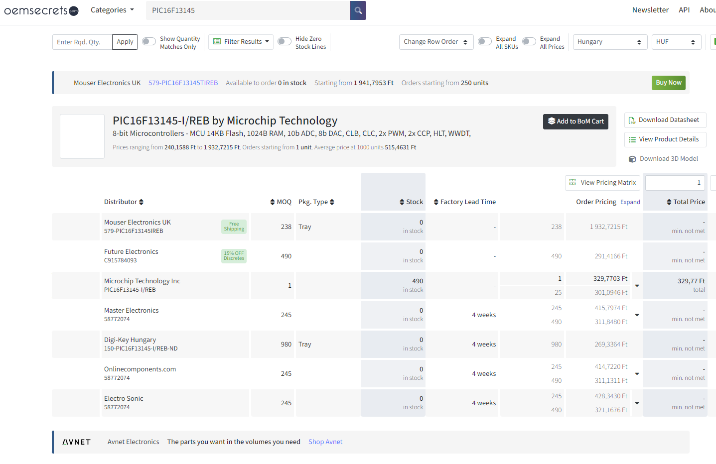
Preisvergleich für Microchip PIC16F13415-I/REB Mikrocontroller
UK 579-PIC16F13415TIREB 238 Tray 0 in stock 238 1 932,7215 F 1932,7215 F Future Electronics C915784093 490 0 in stock 490 291,4166 F Microchip Technology Inc PIC16F13415-I/REB 1 245 329,7703 F 329,7703 F Master Electronics 58772074 245 0 in stock 4 weeks 490 415,7974 F 311,8480 F Digi-Key Hungary 150-PIC16F13415-I/REB-ND 980 Tray 0 in stock 4 weeks 980 269,3364 F 311,8480 F Onlinecomponents.com 58772074 245 0 in stock 4 weeks 245 414,7220 F 311,1311 F Electro Sonic
in „Microchip CLB – erste Versuche zur „FPGA-Zelle“ im Achtbitter“ · Mikrocontroller und Digitale Elektronik · · Screenshots
-
Datei
LED_Blink.asm
konfiguriert: Ein-Ausgänge der Ports, Anfangszustand von Variablen, ;zuschalten von Funktionen wie Timer1 (bei anderen PICs ADC,PWM,I2C usw). ; ;Zur Belegung von PORTA, PORTB Datenblatt beachten: ;"TABLE 1-1: PIC16F84A PINOUT DESCRIPTION" und "4.0 I/O PORTS" ;Auf jeden Fall müssen erst mal die verwendeten
in „PIC16f84a: startet nicht/nur bei quarz berühren“ · Mikrocontroller und Digitale Elektronik ·
-
PDF
Elektronikladen07.pdf
Assemblercode verzichtet werden kann. PROGRAMMVERSIONEN Sie können sich entscheiden zwischen folgenden PIC-C Versionen: ▯ PCM: Commandline-Compiler für alle Typen mit 14 Bit breitem Befehlswort, z.B. PIC16C6x, PIC16C7x, PIC16C84, PIC16C92x und PIC14000 ▯ PCB: Commandline-Compiler für alle Typen mit 12 Bit
in „MC68000 von Motorolla“ · Mikrocontroller und Digitale Elektronik ·
-
PDF
si-prog-v2_2.pdf
C21 1 1K U9 PIC16Fxx J8 B U4 2 1 RA2 RA1 18 100nF 1 B U13 8 VCC CS 1 3 2 RA3 RA0 17 R17 1K 2 1 A0 VCC 8 7 PE CLK 2 4 3 RA4/T0CKI OSC1/CLKIN 16 3 2 7 C7 6 3 4 15 C16 3 A1 TEST 6 100nF 5 ORG DI 4 5 5 MCLR OSC2
in „Grundlagen: Teilen binär Teil 1 - Vorzeichenlose Ganzzahlen“ · Projekte & Code ·