-
PDF
en.x-nucleo-iks01a2_quick_start_guide.pdf
for NUCLEO-F401RE or NUCLEO-L053R8 or NUCLEO-L152RE or NUCLEO-L476RG \STM32CubeExpansion_MEMS1_V3.0.0\Projects\Multi\Examples\IKS01A2\DataLog\Binary\STM32F401RE-Nucleo \STM32CubeExpansion_MEMS1_V3.0.0\Projects\Multi\Examples\IKS01A2\DataLog\Binary\STM32L053R8-Nucleo \STM32CubeExpansion_MEMS1_V3.0.0\Projects\Multi\Examples\IKS01A2\DataLog\Binary\STM32L476RG-Nucleo 6 drag and drop DataLog.bin for F4 or for L0 or for L1 or for L4 on Nucleo drive Open
in „LSM6DSL Gyro+Accelerometer, Gyro gibt keine Werte aus.“ · Mikrocontroller und Digitale Elektronik ·
-
PDF
fiostdv20_datasheet.pdf
laboratories as well as a stand-alone system for used in-the-field in MINIMUM REQUIREMENTS any student’s science and engineering Minimum requirements for FiO Std to fully projects. function with RapidSTM32 Blockset. TM When used together with RapidSTM32 Matlab 2009a (v7.8) Blockset, FiO Std offers several
in „Aimagin FioStd wird nicht mehr erkannt.“ · Mikrocontroller und Digitale Elektronik ·
-
Datei
Files.txt
); LCD_WR_DATA(0xef); // EXIT SLEEP (S-101) LCD_WR_REG(0x11); CS_Inactive(); HAL_Delay(120); CS_Active(); // DISPLAY ON (S-109) LCD_WR_REG(0x29); } // Das ist die Display.h #ifndef SRC_DISPLAY_H_ #define SRC_DISPLAY_H_ #include "stm32f3xx_hal.h
in „Probleme das Ili9341 Board zum laufen zu bekommen“ · Mikrocontroller und Digitale Elektronik ·
-
Datei
stm32746g_discovery_lcd.h
** @defgroup STM32746G_DISCOVERY_LCD_Exported_Types STM32746G_DISCOVERY_LCD Exported Types * @{ */ typedef struct { uint32_t TextColor; uint32_t BackColor; sFONT *pFont; }LCD_DrawPropTypeDef; typedef struct { int16_
in „STM32F7 Disco und das Display-->hard fault error“ · Mikrocontroller und Digitale Elektronik ·
-
Datei
ws2812.c
>50us >50us >280us * * WS2813 is not supported (timing values out of range). * * WS2812 format : (8G 8R 8B) * 24bit per LED (24 * 1.25 = 30us per LED) * 8bit per color (MSB first) * * After each frame of n LEDs there has to be a pause of >= 50us (WS2812S chinese version: >= 280us) * * This program
in „WS2812B mit Lib von Martin Hubáček auf F103“ · Mikrocontroller und Digitale Elektronik ·
-
PDF
STM32F746G_Discovery.pdf
PB_USERR_USEPISPISPIR1PIR1502 POUSD0CLK SB6B6 10K 2 PuSD_CMDD P2 R1616 NI2040CP78 100nF 10K 1 2 3 4 5 6 7 8 P0 0 PJS008-2003 SMS064FF or SMS128FF 3V3 2 1 92 S S COR9 9 0 91NA] P91 PUSD_tect PIR8PIR802 Input pin with pull-up402 TitJoystick, ACP, LEDs and Push Button ProjSTM32F746G-DISCO Size: AReference: MRevision
in „STM32F7 Discovery Board“ · Mikrocontroller und Digitale Elektronik ·
-
PDF
MB997.pdf
R1313 D2D L E PIR50PIR502 _ _ _ _ J SWD 10K10 R2R2 AIN_10 U R I I IMR I M P I D P I D 2 01002021 F S S S S S S S OCN BAT60JFILM E E Not Fitted 3V 8 7 6 5 4 3 2 1 0 9 8 7 CN2 R1212 T_JTCKC D R P4 4 4 4 4 4 4 4 4 3 3 3 U2U 2 PICN202 PIR12P221202 PISB3B3ISB302 PISB2B2ISB202 3V __ B B T B B B SO D K STM32F103C8T6
in „Mit STM32F4 einen Laser ansteuern“ · Mikrocontroller und Digitale Elektronik ·
-
Datei
startup_stm32f4xx.c
/** ****************************************************************************** * @file startup_stm32f4xx.s * @author Coocox / UB (angepasst fuer STM32F429) * @version V1.1 * @date 10/27/2013 * @brief STM32F429 Devices vector table for RIDE7 toolchain. * This module performs: * - Set the initial SP
in „STM32F429 Disco Board: SDRAM benutzen“ · Mikrocontroller und Digitale Elektronik ·
-
Datei
startup_stm32f429x.c
/** ****************************************************************************** * @file startup_stm32f4xx.s * @author Coocox / UB (angepasst fuer STM32F429) * @version V1.1 * @date 10/27/2013 * @brief STM32F429 Devices vector table for RIDE7 toolchain. * This module performs: * - Set the initial SP
in „STM32F4 GCC Toolchain: syscalls.c printf und malloc Errors“ · Mikrocontroller und Digitale Elektronik ·
-
Datei
startup_stm32f429x.c
/** ****************************************************************************** * @file startup_stm32f4xx.s * @author Coocox / UB (angepasst fuer STM32F429) * @version V1.1 * @date 10/27/2013 * @brief STM32F429 Devices vector table for RIDE7 toolchain. * This module performs: * - Set the initial SP
in „STM32F4 Linker Scripte: Ich will es jetzt kapieren!“ · Mikrocontroller und Digitale Elektronik ·
-
Datei
startup_stm32f429.c
/** ****************************************************************************** * @file startup_stm32f4xx.s * @author Coocox / UB (angepasst fuer STM32F429) * @version V1.1 * @date 10/27/2013 * @brief STM32F429 Devices vector table for RIDE7 toolchain. * This module performs: * - Set the initial SP
in „STm32Fxxx: Kleiner Gefallen vom einem Profi erbeten“ · Mikrocontroller und Digitale Elektronik ·
-
Datei
system_stm32f0xx.c
whenever the core clock is changed * during program execution. * * 2. After each device reset the HSI (8 MHz Range) is used as system clock source. * Then SystemInit() function is called, in "startup_stm32f0xx.s" file, to * configure the system clock before to branch to main program. * * 3. If the system
in „STM32 Takt Frage“ · Mikrocontroller und Digitale Elektronik ·
-
PDF
stm32h745_timer_and_dma_and_dac.pdf
r3, =_si_dma_data ldr r3, [r3, r1] str r3, [r0, r1] adds r1, r1, #4 LoopDMACopyDataInit: ldr r0, =_s_dma_data ldr r3, =_e_dma_data adds r2, r0, r1 cmp r2, r3 bcc CopyDMADataInit ldr r2, =_sbss b LoopFillZerobss /* Zero fill the bss segment. */ STM32H745 Timer & DMA& DAC 1. Mar. 2021 8/11 Figure 14: Diff of the startup_stm32h745zitx.s with added initialization. STM32H745 Timer & DMA& DAC 1. Mar. 2021 9/11 Implementation In this example the implementation is in main.c . In order to place a variable into theAXI it requires
in „komplexes Problem mit Grafik und Dateisystem auf Disco-F746NG“ · Mikrocontroller und Digitale Elektronik ·
-
Datei
stm32f0xx_hal_conf.h
" #endif /* HAL_DAC_MODULE_ENABLED */ #ifdef HAL_FLASH_MODULE_ENABLED #include "stm32f0xx_hal_flash.h" #endif /* HAL_FLASH_MODULE_ENABLED */ #ifdef HAL_I2C_MODULE_ENABLED #include "stm32f0xx_hal_i2c.h" #endif /* HAL_I2C_MODULE_ENABLED */ #ifdef HAL_I2S_MODULE_ENABLED #include "stm32f0xx_hal_i2s.h" #endif /* HAL_I2S_MODULE_ENABLED */ #ifdef HAL_IRDA_MODULE_ENABLED #include "stm32f0xx_hal_irda.h" #endif /* HAL_IRDA_MODULE_ENABLED */ #ifdef HAL_IWDG_MODULE_ENABLED #include "stm32f0xx_hal_iwdg.h" #endif /* HAL_IWDG_MODULE_ENABLED
in „STM32F0 Verständnisproblem Clock Konfiguration bzw. Clock Tree“ · Mikrocontroller und Digitale Elektronik ·
-
PDF
en.DM00072315.pdf
embedding bootloader versions V5.x, V6.x,V7.x, V8.x, V9.x, V10.x, V11.x and V13.x, as specified in the application note AN2606 “STM32 microcontroller system memory boot mode”, available on www.st.com. These products are listed in Table 1, and are referred
in „STM32 I2C zu Bootloader“ · Mikrocontroller und Digitale Elektronik ·
-
Datei
oled_demo.c
nicht zwischen den Controllern // unterschieden werden muss #define readfont(a,c) pgm_read_byte(&font8x8[(a)-32][c]) #elif defined(STM8S) /* ------------------------------------------------------------ STM8S-Mikrocontroller mit SDCC Compiler ------------------------------------------------------------
in „I2C Display einfache Frage“ · Mikrocontroller und Digitale Elektronik ·
-
Datei
main.c
configured, this is done through SystemInit() function which is called from startup file (startup_stm32f2xx.s) before to branch to application main. To reconfigure the default setting of SystemInit() function, refer to system_stm32f2xx.c file */ /* Initialize LEDs on STM322xG-EVAL board */ STM_EVAL_LEDInit
in „STM3220G-EVAL + Kamera OV2460“ · Mikrocontroller und Digitale Elektronik ·
-
PDF
STMxx-Discovery-Versaloon-How2-pict.pdf
The finished STM8S SWD debugger Blue wires on JTAG , and SWDwires on CN7 Purple = SWDIO - Green = GND – White= SWCLK And the STM32VL end of the wires from the STM8S above Here i haven't modified the STM32VL , and is using the STM8S as SWD programmer for the value-line chip Shows both boards There the wires used on the signalyzer-lite JTAG dongle And the other end of the Signalyser wires The complete STM8S conversion/test setup
in „Use your STMxx-Discoveryboard as JTAG (SWD)“ · Mikrocontroller und Digitale Elektronik ·
-
Datei
parse_ioc.py
schematic.", file=sys.stderr) return lib_block = sch_content[lib_start:lib_end] # Find the specific STM32 symbol template inside lib_symbols # e.g., (symbol "MCU_ST_STM32F4:STM32F411CEUx" ... ) symbol_match = re.search(r'\(\s*symbol\s+"([^"]*STM32[^"]*)"', lib_block, re.IGNORECASE) if not symbol_match
in „Skript zur Synchronisierung KiCAD/STM32CubeMX“ · Platinen ·
-
Datei
main.c
configured, this is done through SystemInit() function which is called from startup file (startup_stm32f4xx.s) before to branch to application main. To reconfigure the default setting of SystemInit() function, refer to system_stm32f4xx.c file */ /* Initialize Leds mounted on STM32F4-Discovery board
in „STM32F4 SysTick Fehler ?“ · Mikrocontroller und Digitale Elektronik ·
-
Datei
system_stm32f0xx.c
whenever the core clock is changed * during program execution. * * 2. After each device reset the HSI (8 MHz Range) is used as system clock source. * Then SystemInit() function is called, in "startup_stm32f0xx.s" file, to * configure the system clock before to branch to main program. * * 3. If the system
in „STM32F030F4P6 und USART1“ · Mikrocontroller und Digitale Elektronik ·
-
Datei
stm32f4xx_conf.h
include "stm32f4xx_adc.h" #include "stm32f4xx_can.h" #include "stm32f4xx_crc.h" #include "stm32f4xx_cryp.h" #include "stm32f4xx_dac.h" #include "stm32f4xx_dbgmcu.h" #include "stm32f4xx_dcmi.h" #include "stm32f4xx_dma.h" #include "stm32f4xx_exti.h" #include "stm32f4xx_flash.h" #include "stm32f4xx_fsmc.h" #include "stm32f4xx_hash.h" #include "stm32f4xx_gpio.h" #include "stm32f4xx_i2c.h" #include "stm32f4xx_iwdg.h" #include "stm32f4xx_pwr.h
in „STM32F4 SPI Problem“ · Mikrocontroller und Digitale Elektronik ·
-
PDF
en.DM00091010.pdf
/x6/x8/xC and STM32F070x6/xB microcontroller memory and peripherals. It applies to STM32F030x4/x6/x8/xC and STM32F070x6/xB devices. For the purpose of this manual, STM32F030x4/x6/x8/xC and STM32F070x6/xB microcontrollers
in „EFM32F030 und Standby“ · Mikrocontroller und Digitale Elektronik ·
-
Datei
External_Interrupts_H7_HAL_bindings.txt
for h in `cat startup_stm32h743xx.s | grep 'Handler ' | grep '.word' | awk '{print $2}'`; do echo $h; find ./STM32H7xx_HAL_Driver -name \*.h -exec /usr/bin/grep -H $h {} \;; done WWDG_IRQHandler ./STM32H7xx_HAL_Driver/Inc/stm32h7xx_hal_wwdg.h
in „Q: STM32H743 External Interrupts HAL bindings“ · Mikrocontroller und Digitale Elektronik ·
-
Datei
main.c
============== - this file must be inserted in a project containing the following files : o system_stm32l0xx.c, startup_stm32l053xx.s o stm32l0xx.h to get the register definitions o CMSIS files =============================================================================== ##### How to test this example
in „STM32: SysTick_Config“ · Mikrocontroller und Digitale Elektronik ·
-
Datei
system_stm32f4xx.c
SystemCoreClock >>= tmp; } #if defined (DATA_IN_ExtSRAM) && defined (DATA_IN_ExtSDRAM) #if defined(STM32F427xx) || defined(STM32F437xx) || defined(STM32F429xx) || defined(STM32F439xx) ||\ defined(STM32F469xx) || defined(STM32F479xx) /** * @brief Setup the external memory controller. * Called in startup_stm32f4xx.s
in „STM32F4 Discovery Audio CS43L22 I2C Problem“ · Mikrocontroller und Digitale Elektronik ·
-
Datei
Quellcode.c
#include <stm32f10x_lib.h> // STM32F10x Library Definitions #include "STM32_Init.h" // STM32 Initialization #define S3 0x00002000 // PC13: S3 #define S2 0x00000001 // PA0 : S2 #define UNBOUNCE_CNT 5 // unbounce the
in „Unverständnis bei Pinauswahl ARM“ · Mikrocontroller und Digitale Elektronik ·
-
Datei
debugme.c
_PB13_PB14, }; #define SPI_CALIPER spi_caliper_STM32F4XX_SPI2_PB13_PB14 /** Messschieber per SPI einlesen - simplex mode (RM0390 S. 850f.) - Steigende Flanke, Zweite Flanke -> CPHA=0, CPOL=0 - MOSI bleibt drin, bis alles getestet ist */ void spi_caliper_init
in „STM32F4XX SPI Slave“ · Mikrocontroller und Digitale Elektronik ·
-
PDF
STM_DEV.pdf
Title SizeA4 Number7. Revision: Date: 16.01.2010Time: 17:31:15Sheet 7 of 7 FileC:\Projekte\ALTIUM\STM-DEV\JTAG.SchDoc 1 2 3 4 COSS7 A2PS4A06S8A1PS2A04S6P78S2 A1PS3A05S7A09S1A03S5PS7S9 COSS5 COSS4 55A1351A09S7A0 S3PS1 S5P03S1 S9A07S5A03S1 56A1452A1PS8A06S4PS2 S6P04S2P41A08S6A0PS2 COSS1 COSS6 S0A02 COCK1COUC1
in „STM32 Development Board“ · Mikrocontroller und Digitale Elektronik ·
-
Datei
Code_Test_23062023.txt
Incremental Build of configuration Debug for project Schwarze Platine - Thermoelement_23062023 **** make -j8 all arm-none-eabi-gcc "../Core/Src/LM235Z.c" -mcpu=cortex-m4 -std=gnu11 -g3 -DDEBUG -DUSE_HAL_DRIVER -DSTM32F411xE -c -I../Core/Inc -I../Drivers/STM32F4xx_HAL_Driver/Inc -I../Drivers/STM32F4xx_HAL_Driver
in „DAC mit STM32CubeIDE und STM32F411CEU unter Linux“ · Mikrocontroller und Digitale Elektronik ·
-
PDF
reference_manual.pdf
settable TIM8_CC TIM8 Capture Compare interrupt 0x0000_00F8 Doc ID 13902 Rev 14 197/1096 Interrupts and events RM0008 Table 63. Vector table for other STM32F10xxx devices (continued) n t i r Type of s r priority Acronym
in „I2S zwischen STM32F103RET6 und PCM3168A möglich?“ · Mikrocontroller und Digitale Elektronik ·
-
Datei
onoff.c
################################### STM8S103F3P6 Pinout ################################################################## ------------ UART1_CK / TIM2_CH1 / PD4 | 1 20 | PD3 / AIN4 / TIM2_CH2 / ADC_ETR UART1_TX / AIN5 / PD5 | 2 19 | PD2
in „STM8S - Ein-und Ausschalten der Betriebsspannung“ · Projekte & Code ·
-
PDF
stm32f4_xtal_168mhz_test.pdf
interrupt unused RCC global interrupt unused FPU global interrupt unused * User modified value Page 7 stm32f4_xtal_168mhz_test Project Configuration Report 7. Power Consumption Calculator report 7.1. Microcontroller Selection Series STM32F4 Line STM32F407/417 MCU STM32F407VGTx Datasheet 022152_Rev8 7.2. Parameter Selection Temperature 25 Vdd 3.3 Page 8 stm32f4_xtal_168mhz_test Project Configuration Report 8. Software Project 8.1. Project Settings Name Value Project Name stm32f4_xtal_168mhz_test Project Folder C:\Users\Megaport\Documents\stm32cubemx
in „STM32 Clock Configuration“ · Mikrocontroller und Digitale Elektronik ·
-
PDF
MINI-STM32-Schematic-Diagram.pdf
PI3103RXBDM PB121IP80113 14 PIP80PB1B11 Y1Y NRSTPIU176 PD1 OSC_OUT PA10 PI3003TX PB141IP80115 16 PIP80PB1313 8MHZ P I U 1 0 8T PA9 P I U 1 0 2 9 PA8APIP80197 18 PIP80201515 GND PIC80PIC802 12 GND VDDAP I U 1 VDDA STM32F103 PB15 P I U 1 0 2 8 RX PIP80221 22 PIP8022 20pF PA0 PIU1010 PA0-WKUP PB14 PIU1027B14 GND
in „Löttemperatur STM32“ · Mikrocontroller und Digitale Elektronik ·
-
Datei
spi_caliper_stm32f4xx.c
; GPIO_TypeDef *SCK_GPIOx, *MISO_GPIOx; uint32_t SCK_Pin_x, MISO_Pin_x; uint8_t SPIx_IRQn; switch( SPI_CALIPER ) { case spi_caliper_STM32F4XX_SPI2_PB13_PB14: /* Enable the SPI clock */ RCC_APB1PeriphClockCmd(RCC_APB1Periph_SPI2, ENABLE); SCK_GPIOx = GPIOB; SCK_Pin_x = GPIO_Pin
in „STM32 "SPI"-Slave 24 Bit ohne Chip Select“ · Mikrocontroller und Digitale Elektronik ·
-
Datei
system_stm32f0xx.c
whenever the core clock is changed * during program execution. * * 2. After each device reset the HSI (8 MHz Range) is used as system clock source. * Then SystemInit() function is called, in "startup_stm32f0xx.s" file, to * configure the system clock before to branch to main program. * * 3. If the system
in „STM32F0 Discovery und UART1“ · Mikrocontroller und Digitale Elektronik ·
-
PDF
STM32H7-Disco_full.PDF
Gnd 2 2 2 R41 R42 C36 P81Gnd_Therm P3 150nF 820R P51k P20k P222nF L7987 C37 GND P +14.8V_bat +14.8V 2 2 2 P3820pF R43 SW1 0 1 2 P2k4 J18 2 PW0 2 PI8 1 2 PJ8 4S0 3 P2 Fuseclip 5S0 PW0 PP0TP 1.5mm GND GND J2 PS0 TP19 + SS 13PLP HA 1X18650 - GND P2 +11.1V 2 +5V Imax = 2A P7 P0 J7 +14.8V R44
in „STM32H7-Disco erster Test“ · Mikrocontroller und Digitale Elektronik ·
-
PDF
STM32F746-DISCO-OSCI.pdf
after losing also some hair – found the answer here: (see “mollyandchloe1”) https://community.st.com/s/question/0D50X00009XkY6vSAF/dacadc-conversion-timer-triggering - The STM32F746 has another silicon bug, that can cause frustration and head-(to-table)-banging while debugging. I was wondering that I
in „STM32F746G-DISCO-OSCI mit WAV-Recording auf SD-Karte“ · Projekte & Code ·
-
PDF
Clock_Tree.pdf
) VCO /N TIM15 PLLQCLK / R PLLR PLLRCLK HSI48 PLLQ PLLQCLK PLLQCLK / Q to RNG PLLP PLLPCLK HSI16 / 8 /1,2,4,8 / P SYSCLK SYSCLK async clock to ADC HSI16 PLLPCLK SYSCLK PLLPCLK to I2S1 HSI16 I2S_CKIN I2S_CKIN I2S2 HSI48 (2) HSE to USB PLLQCLK PCLK HSE to FDCAN (2) PLLQCLK BOLD: clock origin 1. Only applies to STM32G071xx and STM32G081xx and to STM32G0B1xx and STM32G0C1xx. 2. Only applies to STM32G0B1xx and STM32G0C1xx. 166/1390 RM0444 Rev 5
in „Problem mit Clock Configuration beim STM32G031“ · Mikrocontroller und Digitale Elektronik ·
-
 Bild
Bild
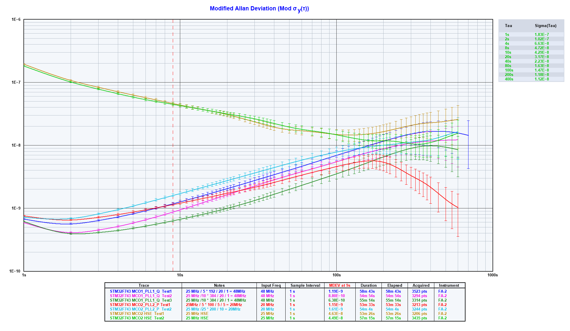
Modified Allan Deviation Diagram
Modified Allan Deviation (Mod σy(τ)) Tau Sigma(Tau) 1s 1.83E-7 2s 1.63E-7 4s 1.32E-7 8s 1.02E-7 10s 9.10E-8 40s 2.23E-8 80s 2.00E-8 100s 1.47E-8 200s 1.12E-8 600s Trace Notes Input Freq Sample Interval MEDEV at 1s Duration Elapsed Acquired Instrument STM32F743
in „STM32H743 PLL“ · Mikrocontroller und Digitale Elektronik · · Diagramme
-
Datei
stm32f429i_discovery_lcd.h
#define LCD_BACKGROUND_LAYER 0x0000 #define LCD_FOREGROUND_LAYER 0x0001 /** * @} */ /** @defgroup STM32F429I_DISCOVERY_LCD_Exported_Macros * @{ */ #define ASSEMBLE_RGB(R, G, B) ((((R)& 0xF8) << 8) | (((G) & 0xFC) << 3) | (((B) & 0xF8) >> 3)) /** * @} */ /** @defgroup STM32F429I_DISCOVERY_LCD_Exported_Functions
in „STM32F429 Display per SPI ansteuern“ · Mikrocontroller und Digitale Elektronik ·
-
Datei
f_mess.c
/* STM32F407 Beispielprogramm für Frequenz- und Pulsweitenmessung an PC6 mit Timer 8. Das Ergebnis wird 6-stellig mit typ. 3 Mess./s oder minimal 1 Periodendauer auf einem LCD-Modul in der 1. Zeile angezeigt
in „Frequenz- und Pulsweitenmessung mit STM32F407“ · Projekte & Code ·
-
Datei
system_stm32f0xx.c
whenever the core clock is changed * during program execution. * * 2. After each device reset the HSI (8 MHz Range) is used as system clock source. * Then SystemInit() function is called, in "startup_stm32f0xx.s" file, to * configure the system clock before to branch to main program. * * 3. If the system
in „uint16_t Division compilerabhängig? HardFault bei bestimmtem Compiler“ · Mikrocontroller und Digitale Elektronik ·
-
Datei
system_stm32l1xx.c
Table base offset field. This value must be a multiple of 0x200. */ /** * @} */ /** @addtogroup STM32L1xx_System_Private_Macros * @{ */ /** * @} */ /** @addtogroup STM32L1xx_System_Private_Variables * @{ */ uint32_t SystemCoreClock = 16000000; __I uint8_t PLLMulTable[9] = {3, 4, 6, 8, 12, 16, 24, 32, 48}; __I uint8_t AHBPrescTable[16] = {0, 0, 0, 0, 0, 0, 0, 0, 1, 2, 3, 4, 6, 7, 8, 9}; /** * @} */ /** @addtogroup STM32L1xx_System_Private_FunctionPrototypes * @{ */ static void SetSysClock(void); /** * @} */ /**
in „STM32L1 + Makefile. Linkerproblem?“ · Mikrocontroller und Digitale Elektronik ·
-
Datei
system_stm32f0xx.c
whenever the core clock is changed * during program execution. * * 2. After each device reset the HSI (8 MHz Range) is used as system clock source. * Then SystemInit() function is called, in "startup_stm32f0xx.s" file, to * configure the system clock before to branch to main program. * * 3. If the system
in „STM32F0 Discovery und UART1“ · Mikrocontroller und Digitale Elektronik ·
-
Datei
system_stm32f0xx.c
whenever the core clock is changed * during program execution. * * 2. After each device reset the HSI (8 MHz Range) is used as system clock source. * Then SystemInit() function is called, in "startup_stm32f0xx.s" file, to * configure the system clock before to branch to main program. * * 3. If the system
in „STM32F0 Discovery und UART1“ · Mikrocontroller und Digitale Elektronik ·
-
PDF
TestArmTurtorialDeu.pdf
Entwicklungsboards mit diesen Controllern verfügbar, zum Beispiel: Nucleo-F103, „/ users / hudakz / code / STM32F103C8T6_Hello / Blue Pill (suchen Sie nach „stm32f103c8t6“ auf AliExpress, Ebay oder Amazon), Quellhardware Olimexino-STM32, STM32-P103, / STM32-H103 / STM32-H103, STM3210E-EVAL. Prozessortyp & Dokumentation
in „ARM-Assembler-Tutorial“ · Mikrocontroller und Digitale Elektronik ·
-
PDF
STM32_5VtolerantIO.pdf
VDD • The voltage higher than VDD is simply translated as high level Application example : I2C 7 • STM32 supplied by 1.8V or 3.3V can directly communicate with 5V I2C bus. VDD=1.8V or 3.3V VDDX=5.0V (max 5.4V when VDD=1.8V) VDDX=5.0V SDA STM32 5V IC SCL • If there is condition when VDD=0V, VDDX=5V(even
in „ESP32 3.3V Logik Level Mosfet“ · Analoge Elektronik und Schaltungstechnik ·
-
Datei
main.c
============== - this file must be inserted in a project containing the following files : o system_stm32f0xx.c, startup_stm32f072xb.s o stm32f0xx.h to get the register definitions o CMSIS files =============================================================================== ##### How to test this example
in „RS485 - viele Teilnehmer - hohe Geschwindigkeit“ · Mikrocontroller und Digitale Elektronik ·
-
Datei
irmp-stm8.diff
SDCC_stm8) // SDCC stm8 target +# define SDCC_STM8 #elif defined(unix) || defined(WIN32) || defined(__APPLE__) // Unix/Linux or Windows or Apple # define UNIX_OR_WINDOWS #else @@ -116,6 +118,15 @@ # define PROGMEM # define memcpy_P memcpy +#elif defined(SDCC_STM8) + +# include "stm8s.h" +# define PROGMEM +# define memcpy_P memcpy +# define __attribute__(x) +# define uint_fast8_t uint8_t +# define uint_fast16_t uint16_t + #else # define PROGMEM