SN74CBTLV3253DR 3689 Stück sofort verfügbar > ... Gehe einen Schritt weiter, da steht was von 6W *. Nach meinen (seltenen) Erfahrungen mit Mouser kommen am Ende 2-3w rum.
I- und Q-Signal, also aller 4us ein I- oder Q-Sample mit einem Jitter von maximal 2us. Das ist bei den auf maximal 12kHz begrenzten I-/Q-Signalen vernachlässigbar. Dies insbesondere auch, weil in der nachfolgenden
1 = ----------------------- 152 PSC0 = 151 Set PWM0 duty cycle to 50 %: 80h -WM0 = 0.5 256 PWM0 = 128 Set prescaler PCS1 to dim at maximum frequency: 00h Blink period = max PSC1 = 0 Set PWM1 output duty cycle to 25 %: 40h -WM1 = 0.25 256 PWM1 = 64 Set LED0 on, LED1 off; LED2 set to blink at PSC0, PWM0
CLKIN OUTPUT-VOLTAGE LOW POWER-SUPPLY CURRENT vs. OUTPUT CURRENT vs. SCL FREQUENCY 0.4 4 200 5 T = +25°C, t T = +25°C, t A 3 A 3 OUT = ECLK = SQWE = 0 D ) OUT = 0mA D µ ) 0.3 T ( E G R 150 T VCC = 1.3V U O Y V 0.2 L 5.0V U U T - O V CC= 3.0V E 100 0.1 W V CC= 5.0V P 3.0V 0 50 0 1 2 3 4 0 100 200 300 400
byte data to register SDA S 1 1 0 0 A2 A1 A0 0 A 0 0 0 AI B3 B2 B1 B0 A DATA 1 A START condition R/W acknowledge acknowledge acknowledge from slave from slave from slave write to register tv(Q) data out from port DATA 1 VALID 002aae526 Fig 11. Write to register slave address command byte (cont.) SDA
1 = ----------------------- 152 PSC0 = 151 Set PWM0 duty cycle to 50 %: 80h -WM0 = 0.5 256 PWM0 = 128 Set prescaler PCS1 to dim at maximum frequency: 00h Blink period = max PSC1 = 0 Set PWM1 output duty cycle to 25 %: 40h -WM1 = 0.25 256 PWM1 = 64 Set LED0 on, LED1 off; LED2 set to blink at PSC0, PWM0
important enough to warrant further investigation, so the equation forBZ is given be- low. ȡ sb 0 ȣ R 1 ) w Z B h ) ib B ȧ T ȧ (8–25) b0) 1 Sb 0 Ȣ 1 ) b )1 w Ǔ ȱ 0 T At low frequencies hib50Ω and R /(βB+1)0= 25 Ω, so Z =7BΩ. Z varieB in accordance with Equation 8–25 at high frequencies. Also, the transistor
wiring plan R PE 1 1 7 Pour les options, reportez-vous O aux schémas complémentaire W W H A1 X1 W5 KSL 4/ 3 2 A121 W , 5 2 W101 H07VVH6-F 8G1,5 M 4 A100 J Z Funkempfänger X100 - 0 Ö radio receiver 2 M 5 2 2 x / W W121 FLGöu-JZ 18x1,5 8 2 1 M Z - W T Q1 Netzanschlussschalter Y M mains
7 R R C D 7 7 7 6 6 6 6 R C R D R767 R655 R W Q D R W R 6 J 8 0 3 (Page 25) C506 R517 JWB03 R R R R R R R R R648 Q R R J 7 J R W 7 7 8 C740 R673 9 1 C822 J 3 JW R 0 0 0 2 2 2 0 4 5 C540 6 4 2 7 5 5 1 4 2 7 4 0 2 5 C640 0 Q656 5 5 7 8 5 9 R6562 H
upon failure of input or output circuitry. PARAMETER TEST CONDITIONS MIN TYP MAX UNIT RθJA = 56.8°C/W, VI= 5.5 V, J = 150°C, 400 TA= 25°C, see Figure 7-1 IS Safety input, output, or supply current mA RθJA = 56.8°C/W, VI= 3.6 V, J = 150°C, 611 TA= 25°C, see Figure 7-1 (1) RθJA = 56.8°C/W, TJ= 150°C, TA
hexadecimal value. This parameter must be written: Group Menu Parameter Parameter name Unit Type Bytes R/W Range Setpoints 004 001 Voltage setpoint V FLOAT32 4 R/W From 0 to 100000 Table 14 - Parameter list line extract Document type : Q1 T xxx – Révision A du 07/12/2020Réf. NT180220 01 RDE FJ A 15/31 Electric
1 = ----------------------- 152 PSC0 = 151 Set PWM0 duty cycle to 50 %: 80h -WM0 = 0.5 256 PWM0 = 128 Set prescaler PCS1 to dim at maximum frequency: 00h Blink period = max PSC1 = 0 Set PWM1 output duty cycle to 25 %: 40h -WM1 = 0.25 256 PWM1 = 64 Set LED0 on, LED1 off; LED2 set to blink at PSC0, PWM0
Bausteine, wie sie für BIOS-Speicher benutzt wurden, zwischen 1 MByte und 16 MByte, gängige ICs waren z.B. W25X80, W25Q80, MX25L80, W25X128x, W25Q128x, MX25L128x, o.ä., auch Zwischenwerte, nur DIP-8-Gehäuse, nur 25er Typen. Fundstelle könnte z.B. ein altes ausrangiertes Motherboard sein. Zweck ist Test einer
Hab ich für dich, 2x 25X80, 1x 25Q80 und einen 25Q16. Wenn du Interesse hast, die stammen alle aus Sockeln, alte Mainboard waren die Quelle. Ich hab sie gerade "geprüft", alle haben noch jungfräuliche Statusregister.
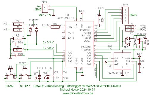
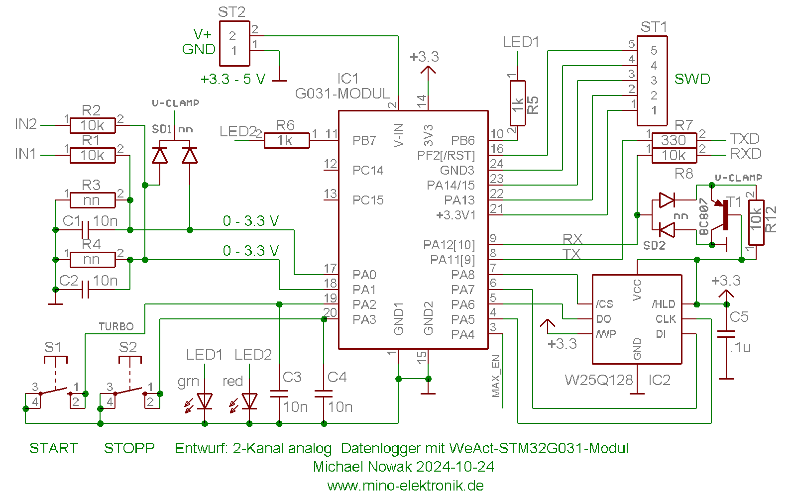
mino-elektronik.de/Gemischtes/2-Kanal%20Datenlogger.html) möchte ich 3 Platinen nebst STM32G031-µC-Modul, W25Q128 und je zwei Stück zum Layout passende Taster für 5 Euro das Set zzgl. Briefversand anbieten. Bei Interesse bitte eine PN mit eigener email-Adresse abschicken.
programmieren, erhalte ich die Fehlermeldung: >>>: avrdude.exe -c arduino -p m328p -P COM3 -b 115200 -U lfuse:w:0x62:m -U hfuse:w:0x00:m -U efuse:w:0x00:m Processing -U lfuse:w:0x62:m Reading 1 byte for lfuse from input file 0x62 Writing 1 byte (0x62) to lfuse *** failed Error: unable to write lfuse (rc
-c avrisp -p com3 -P atmega328p -B 10 -b 19200 -U lfuse:w:0xd2:m -U hfuse:w:0xd9:m -U efuse:w:0xff:m Danach läuft dein 328er eben mit 8Mhz. Allerdings bezweifle ich, dass das ausreichend für WS2812 ist (abgesehen davon dass die Libraries -wie oben gesagt
photo of the transducer is shown in Figure 3.24. Its layout is also shown in Figure 3.25. 101 Maximum displacement +/-5 jm Number of sense fingers, 50 Number of feedback fingers Number of drive fingers, 100 Number of sense fingers Co 60 fF CM 25 fF Cp 1pF Total mass 5.6e-9 kg 451 Q Resonant
1 = ----------------------- 152 PSC0 = 151 Set PWM0 duty cycle to 50 %: 80h -WM0 = 0.5 256 PWM0 = 128 Set prescaler PCS1 to dim at maximum frequency: 00h Blink period = max PSC1 = 0 Set PWM1 output duty cycle to 25 %: 40h -WM1 = 0.25 256 PWM1 = 64 Set LED0 on, LED1 off; LED2 set to blink at PSC0, PWM0
Rainer W. schrieb im Beitrag #7793318: > Na ja, zumindest Mikroprozessoren wie den 6502 oder den Z80 gibt es seit > 1975/76. Da war die Zukunft, wo alles als µC auf einem Chip sitzt, nicht > mehr so fern.
digitalRead (7)) xor digitalRead (14));[/c] so viel schlimmer lesbar als [avrasm]in r24,PINB in r25,PIND in r18,PINC lsr r24 bst r25,7 clr r25 bld r25,0 and r24,r25 eor r24,r18 sbrs r24,0 rjmp 1f sbi PORTB,5 ret 1:cbi PORTB,5 ret[/avrasm] ist? Ich weiß ja nicht. Also wenn schon dann
0.94mm 3.52mΩ Source: by the author The main inductance on the primary side of the transformer WMPP77Q55-1u25 can be calculated by L M,pri,L2 n pri,L2A L,L2and is 61.25➭H (A L,L2= 1.25➭H). The primary side leakage inductance L σ,pri,L2s 241nH (measured directly in the circuit). Transformer WMPP66Q44-1.25
USB CONTROL IC ASS'Y 704-MC7K-B194 1 30 IO-Main P.C.B Ass'y Part List REF NO. DESCRIPTION PART NO. Q'TY REMARK IC(W25Q80DVSNIGT,SOIC-8) 417-MC7K-1222 1 IC7001, CONTROL IC ASS'Y 704-MC7K-B195 1 IC(MKL15Z128VLK4,LQFP-80) 417-SR-1102 1 31 TFT Display L P.C.B Ass'y Part List REF NO. DESCRIPTION PART NO.
W W 5 7 5 R R R JW719 H C J JW822 R W 8 0 IC501 6 6 W 5 C732 7 W J J J 5 7 3 0 0 C750 Q750 C680 R681 W 1 JW823 J C D801 (Page 25) P 0 C C J 5 3 3 2 4 7 4 4 W J C733 8 5 6 J R 7 7 5 5 7 7 5 8 8 0 5 5 7 J 7 N R R573 5 5 6 6 1 7 7 R C D J 4 4 4 6 R667 4 6 6 R R C R D R767 R655 6 W Q 6 6 5 6 6 J 1 3 C C506 JWB03 R R J J R R R R R R R R648 Q R R R J D R J R R W 0 7 (Page 25) 8 C822 J 7 R 5 0 5 1 2 5 8 R517 C540 0 4 2 7 C740 R673 0 C640 0 Q656 6 5 2 R656 W 1 5 R JW501 1 5 5 5 5 6
Enhancement Mode Power MOSFET Thermal Characteristic R Thermal Resistance, Junction-to-Case (Note 2) 2.0 ℃/W θJC Electrical Characteristics (T =25℃unless otherwise noted) C Symbol Parameter Condition Min Typ Max Unit Off Characteristics BV DSS Drain-Source Breakdown Voltage V GSV I =D50μA 100 110 - V DSS Zero
intervention and boosting radio efficiency. With receive sensitivity of -132 dBm @300 bit/s 433 MHz OOK and -128 Bm @300 bit/s 868 MHz 2(G)FSK, the radio ensures robust communication over long distances. At +20 dBm output power and -128 dBm of sensitivity at 868 MHz, 300 bps GFSK makes it possible to achieve a
and Tolls to Software. Secure your free ticket for the trade fair now with the voucher code OEM4ew25 in the TicketShop. [/c]
8 10 12 14 16 18 20 22 24 26 28 30 32 34 36 38 40 SNR (dB) w=24, x=15, y=0, z=0 (Default) w=24, x=15, y=1, z=0 w=30, x=15, y=1, z=0 Figure 6. HiCut Controlled by SNR Metric 9 8 z H ( 7 y n e 6 q r F n 5 t s n 4 r r t 3 i t u i 2 H w = 0x1A00: FM_HICUT_SNR_HIGH_THRESHOLD
026 16 TAB AB 1 2 Transfer A to B 23 00010111 027 17 TBA AB 1 2 Transfer B to A 24 00011000 030 18 ! 25 00011001 031 19 DAA A 1 2 Decimal Adjust A 26 00011010 032 1A ! 27 00011011 033 1B ABA AB 1 2 Add B to A 28 00011100 034 1C ! 29 00011101 035 1D ! 30 00011110 036 1E ! 31 00011111 037 1F ! 32 00100000
Dergute W. schrieb im Beitrag #7769258: > Evtl. steht dann unter /var/log/wassweissichwiedasasfileheisst.log mehr > Info? Nein. Nicht, wenn pulseaudio als per-user Instanz ausgeführt wird.
/share/applications/mate-color-select.desktop $ for i in /proc/*/fd/*; do readlink $i | grep -q /dev/snd/pcm && echo $i | awk -F '/' '{print $3}'; done | uniq $ # keine Ausgabe [/pre]
umstrittenes Thema :-). Ein Kollege hat seine Konstruktionen jahrelang von seinem PC auf eine alte W95-Kiste kopiert. Die hatte ein 5,25"-Laufwerk mit 720k. Mit der Diskette ist er dann in den Keller zur CP/M-basierten Sinumerik, die die Fräse steuerte. Ich habe ihm mal einen Gotek mitgebracht, aber
Köpfe und deren Oberflächen sehen. Ist keine Diskette eingelegt, ist der obere Kopf eh' angehoben, ein Q-Tip o.ä. mit Isopropylakohol wirkt hier besser und gründlicher als so eine Diskette. Wenn man die gebraucht kauft, ist da auch der Dreck der vorherigen Benutzer mit drauf ....
1 ESP-RISC-V CPU GoBack Register 1.6. misa (0x301) d) re X ee M ( Z Y X W V U T S R Q P O N M L K J I H G F E D C B A 31 3029 26 25 24 23 22 21 20 19 18 17 16 15 14 13 12 11 10 9 8 7 6 5 4 3 2 1 0 0x1 0x0 0 0 0 0 0 1 0 0 0 0 0 0 0 1 0 0 0 1 0 0 0 0 0 1 0 0 Reset MXL Machine
es heute mit Sone ausgedrückt. Nach Zwicker und Sone suchen. https://www.startpage.com/do/dsearch?q=sone++zwicker&cat=web&language=deutsch https://de.wikipedia.org/wiki/Lautheit https://de.wikipedia.org/wiki/Sone Ich sehe gerade, während ich noch geschrieben habe, hat laberkopp schon links auf
Dergute W. schrieb im Beitrag #7772381: > Sowas? Oder ganz was anderes? Das ist quasi schon die Lösung mit Schleifchen. Aber wow, geht genau in die Richtung, ja, und ob ich da noch nen ATTiny verbaue, tut
1 = ----------------------- 152 PSC0 = 151 Set PWM0 duty cycle to 50 %: 80h -WM0 = 0.5 256 PWM0 = 128 Set prescaler PCS1 to dim at maximum frequency: 00h Blink period = max PSC1 = 0 Set PWM1 output duty cycle to 25 %: 40h -WM1 = 0.25 256 PWM1 = 64 Set LED0 on, LED1 off; LED2 set to blink at PSC0, PWM0
wohl dem Grafikdisplay geschuldet. Chris H. schrieb im Beitrag #7761774: > IMG_2301.jpeg Ein IS25LP032 SPI 32Megabit EEPROM. An dem müsste Spannung dran sein und bei startenden/laufendem Mikrocontroller auch rege Kommunikation. Pinout siehe Datenblatt https://www.issi.com/WW/pdf/IS25LP032-064-128
Stelle (siehe Foto) messe ich 4,85V, die habe ich bisher auf der Platine nicht wiedergefunden. An dem IS25LP032 liegen 3,3V an. An dem M24512-W liegen 3,3 V an. Wenn ich das Display anschließe, leuchtet es hell (siehe Bild). Am V850 liegt an Pin 1 3,3V an. Wenn ich auf Pin 14 (Reset) 3,3V gebe, geht das Display
später per PC auszuwerten. Hierzu ein Schaltungsvorschlag mit einem STM32G031F µC und einen SPI-Flash W25Q128, der mit einer passenden Batterie oder besser LiIon-Zelle betrieben werden kann. Mit bis zu 1000 Messungen/s und einem Kanal reicht der Speicherplatz für gut zwei Stunden. Mit 1 Messung/s für
Schaltung verwendet ein fertiges µC Modul (WeACT STM32G031), welches noch mit einem SPI-Flash (hier W25Q128) und ein paar diskreten Bauteilen nach Bedarf ergänzt werden muß bzw. kann. Damit ist ein Aufbau auf Lochrasterplatine möglich. Eine genauere Beschreibung findet sich hier: http://mino-elektronik.de
keine Probleme gibt wenn VCC stabil ist und Pullups an den wichtigen Leitungen dran sind. @Rick und W25Q128: War warm == heiss ( > 85°C )?
Udo K. schrieb im Beitrag #7760915: > W25Q128: War warm == heiss ( > 85°C )? Schwer zu sagen. Eher so zwischen 60°C und 75°C. Falk B. schrieb im Beitrag #7760919: > Das klingt nach Latch Up. Da ist was beim Einschalten schief gegangen
avrdude: Device signature = 0x2e6176 avrdude: Expected signature for ATmega328P is 1E 95 0F avrdude> q >>> q avrdude done. Thank you. Meine Frage ist beim ersten Bespiel etwas besonderes zu beachten oder ist mein erster IC einfach direkt kaputt? Vielen Dank schonmal für Antowrten....
-2345678-1-2345678-2-2345678-3-2345678-4-2345678-5-2345678-6-2345678-7-23456 von: Dergute W. (derguteweka)schrieb im Beitrag #7913295: 25.07.2025 19:31 Günter K. schrieb: >> also nur mit logischen Befehlen. > > Wenn du nur mit logischen Befehlen rechnen wuerdest, braeuchtest du ja > nur
CPU + VIA (reichelt, ca. 20EUR beide), die Raspi Pico (ca 12EUR sowohl ein RP2040 und einen RP2040W), Ram 128k, 3v3: 6,00EUR, Huehnerfutter: 10Eur = 65EUR (wenn man bedenken tut, dass der Junior 1980 450DEM(*) gekostet hat bekommt man Pippi im Auge). Das ist kein Bausatz, Eigenverantwortung ist
1 ESP-RISC-V CPU GoBack Register 1.6. misa (0x301) d) re X ee M ( Z Y X W V U T S R Q P O N M L K J I H G F E D C B A 31 3029 26 25 24 23 22 21 20 19 18 17 16 15 14 13 12 11 10 9 8 7 6 5 4 3 2 1 0 0x1 0x0 0 0 0 0 0 1 0 0 0 0 0 0 0 1 0 0 0 1 0 0 0 0 0 1 0 0 Reset MXL Machine
specification. OH1 OH 10.Pin capacitance is characterized but not tested. Pin capacitance is less than 25pF. Pin capacitance of ceramic package is less than 15pF (except EA is 25pF). 2000 Jan 20 21 Philips Semiconductors Product specification 80C51 8-bit microcontroller family 4K/128 OTP/ROM/ROMless, low

 Bild