-
 Bild
Bild
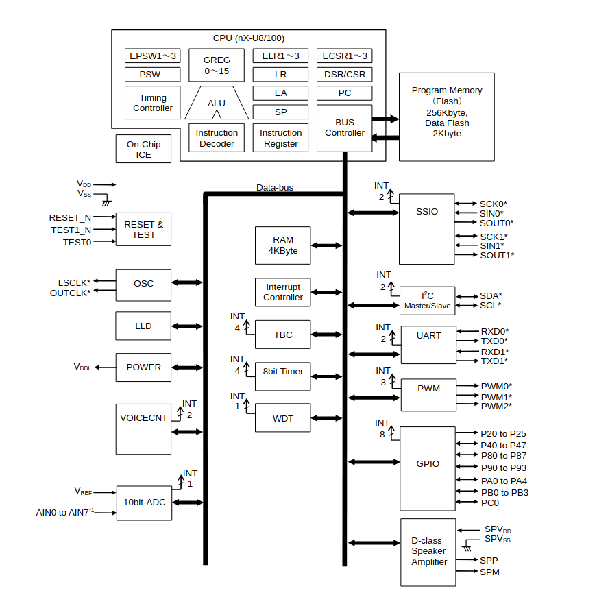
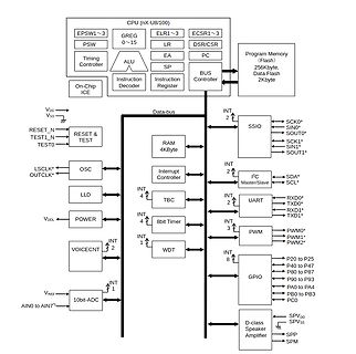
Blockschaltbild eines Mikrocontrollers
INT 2 I2C Master/Slave SDA* SCL* UART RXD0* TXD0* RXD1* TXD1* INT 4 Interrupt Controller TBC INT 3 PWM PWM0* PWM1* PWM2* INT 4 8bit Timer WDT INT 1 OSC OUTCLK* LSCLK INT 2 VOICECNT INT 1 10bit-ADC AIN0 to AIN7* VREF VDD VSS LLD POWER P20 to P25 P40 to P47 P80 to P87 P90 to P93 PA0 to PA4 PB0 to PB3 PC0
in „Neue Bauteile: Steckplatinen-PCB, medizinische Piepser und vieles andere mehr“ · Mikrocontroller und Digitale Elektronik · · Diagramme
-
Datei
freqpwm2.c
/* Title: AVR-GCC test program freqpwm1 for the STK200 eva board Purpose: small PWM generator needed Software: AVR-GCC */ #include <io.h> #include <io2313.h> #include <sig-avr.h> #include <interrupt.h> #define OC1 PB3 SIGNAL(SIG_OVERFLOW1) { __outw(3000,OCR1); //setzt das Output-Compare
-
Datei
freqpwm2_c.c.txt
/* Title: AVR-GCC test program freqpwm1 for the STK200 eva board Purpose: small PWM generator needed Software: AVR-GCC */ #include <io.h> #include <io2313.h> #include <sig-avr.h> #include <interrupt.h> #define OC1 PB3 SIGNAL(SIG_OVERFLOW1) { __outw(3000,OCR1); //setzt das Output-Compare
in „Resetschaltung/PWM“ · Mikrocontroller und Digitale Elektronik ·
-
Datei
IOConfig.h
A R E */ #define DCC_Input RB3 #define initPorts() TRISB = 0b00001000; TRISA = 0b11000000; #define PWM_Port1 RB1 #define PWM_Port2 RB0 #define LED_FRONT RB2 #define LED_REAR RB4 #define LED_EXTRA RB5 //#define DCC_Input GPIO3 //#define initPorts() TRISIO = 0b00001000; //#define PWM_Port1 GPIO0 //#define PWM_Port2 GPIO1 //
in „DCC Lokdecoder PIC16F628“ · Mikrocontroller und Digitale Elektronik ·
-
 Bild
Bild
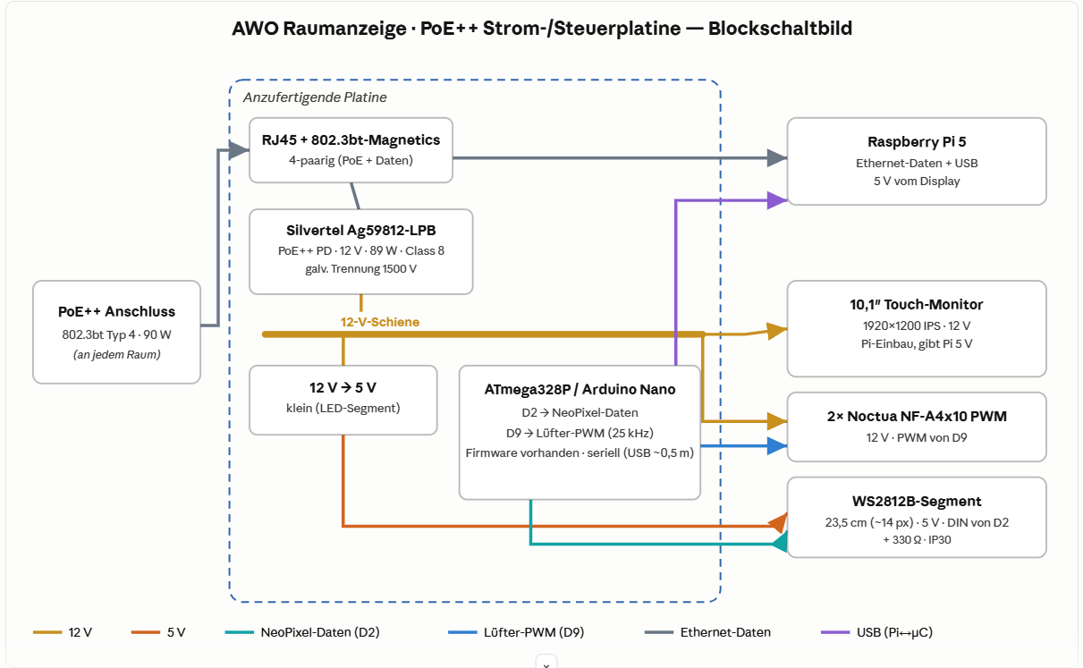
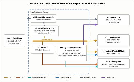
Blockschaltbild einer Strom- und Steuerplatine
Pi 5 V 12 V -> 5 V klein (LED-Segment) ATmega328P / Arduino Nano D2 -> NeoPixel-Daten D9 -> Lüfter-PWM (25 kHz) Firmware vorhanden · seriell (USB ~0,5 m) 2x Noctua NF-A4x10 PWM 12 V · PWM von D9 WS2812B-Segment 23,5 cm (~14 px) · 5 V · DIN von D2 + 330 Ω · IP30 12 V 5 V NeoPixel-Daten (D2) Lüfter-PWM
in „Projekt AWO-Raumanzeige — Hilfe/Umsetzung einer PoE++ Strom- & Steuerplatine gesucht (Raspberry Pi)“ · Platinen · · Diagramme
-
PDF
STC12C2052AD-english.pdf
counter 0 input ECI PCAcount input P3.5 common I/O port PORT3[5] T1 Timer/counter 1 input P3.5/T1/PCA1/PWM1 9 13 11 9 PCA1 PCAmodule 1 Capture input PWM1 PWM module 1 output P3.7 common I/O port PORT3[7] P3.7/PCA0/PWM0 15 19 17 11 PCA0m iPCAmodule 0 Capture input L PWM0 PWM module 0 output RST 31 3 3 1 Reset
in „Uhrzenbausatz mit At89C2051 funktioniert nicht“ · Mikrocontroller und Digitale Elektronik ·
-
PDF
TPS40060_TPS40061.pdf
PROGRAMMING THE RAMP GENERATOR CIRCUIT The ramp generator circuit provides the actual ramp used by the PWM comparator. The ramp generator provides voltage feed-forward control by varying the PWM ramp slope with line voltage, while maintaining a constant ramp magnitude. Varying the PWM ramp directly with
in „Parameter-Berechnung für Schaltregler“ · Analoge Elektronik und Schaltungstechnik ·
-
Datei
Configuration.h
=========================================================== // @section extras // Increase the FAN PWM frequency. Removes the PWM noise but increases heating in the FET/Arduino //#define FAST_PWM_FAN // Use software PWM to drive the fan, as for the heaters. This uses a very low frequency // which is not as annoying as with the hardware PWM. On the other hand, if this frequency // is too low, you should also increment SOFT_PWM_SCALE. //#define FAN_SOFT_PWM // Incrementing this by 1 will double the software PWM frequency, // affecting heaters
in „Marlin Firmware mit dem ATMEL STUDIO 7 auf das Arduino Mega 2560 Board flashen“ · Mikrocontroller und Digitale Elektronik ·
-
Datei
Configuration.h
=========================================================== // @section extras // Increase the FAN PWM frequency. Removes the PWM noise but increases heating in the FET/Arduino //#define FAST_PWM_FAN // Use software PWM to drive the fan, as for the heaters. This uses a very low frequency // which is not as annoying as with the hardware PWM. On the other hand, if this frequency // is too low, you should also increment SOFT_PWM_SCALE. //#define FAN_SOFT_PWM // Incrementing this by 1 will double the software PWM frequency, // affecting heaters
in „Marlin Firmware mit dem ATMEL STUDIO 7 auf das Arduino Mega 2560 Board flashen“ · Mikrocontroller und Digitale Elektronik ·
-
Datei
Configuration.h
=========================================================== // @section extras // Increase the FAN PWM frequency. Removes the PWM noise but increases heating in the FET/Arduino //#define FAST_PWM_FAN // Use software PWM to drive the fan, as for the heaters. This uses a very low frequency // which is not as annoying as with the hardware PWM. On the other hand, if this frequency // is too low, you should also increment SOFT_PWM_SCALE. //#define FAN_SOFT_PWM // Incrementing this by 1 will double the software PWM frequency, // affecting heaters
in „Marlin Firmware mit dem ATMEL STUDIO 7 auf das Arduino Mega 2560 Board flashen“ · Mikrocontroller und Digitale Elektronik ·
-
PDF
CSR1010_Data_Sheet_CS-231985-DS.pdf
release note. CSR1010 QFN has 3 general-purpose analogue interface pins, AIO[2:0]. 5.5 LED Flasher / PWM Module CSR1010 QFN contains an LED flasher / PWM module. Note: The LED flasher functions in Deep Sleep and Active modes only. The PWM functions in all modes except Hibernate and Dormant. These functions
in „I²C Daten über Bluetooth übertragen?“ · Mikrocontroller und Digitale Elektronik ·
-
 Bild
Bild
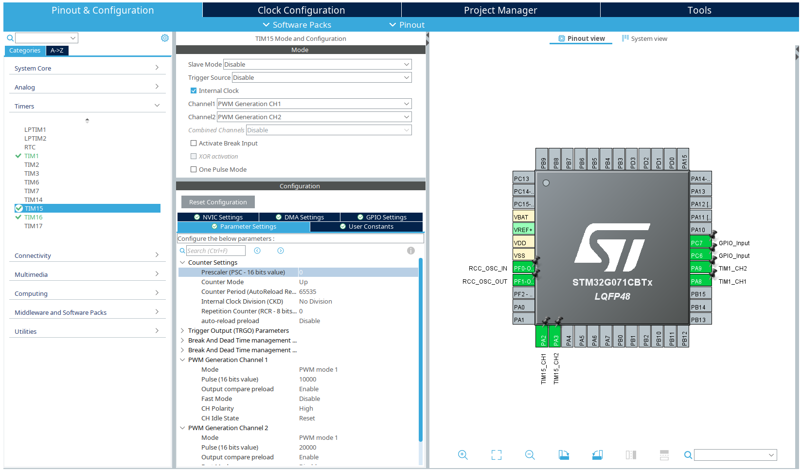
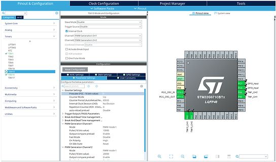
Software-Konfiguration und Pinout-Ansicht eines STM32 Mikrocontrollers
Mode and Configuration, Mode, Slave Mode Disable, Trigger Source Disable, Internal Clock, Channel1 PWM Generation CH1, Channel2 PWM Generation CH2, Combined Channels Disable, Activate Break Input, XOR activation, One Pulse Mode, Configuration, Reset Configuration, NVIC Settings, DMA Settings, GPIO Settings
in „STM32 - Timer steht still“ · Mikrocontroller und Digitale Elektronik · · Screenshots
-
 Bild
Bild
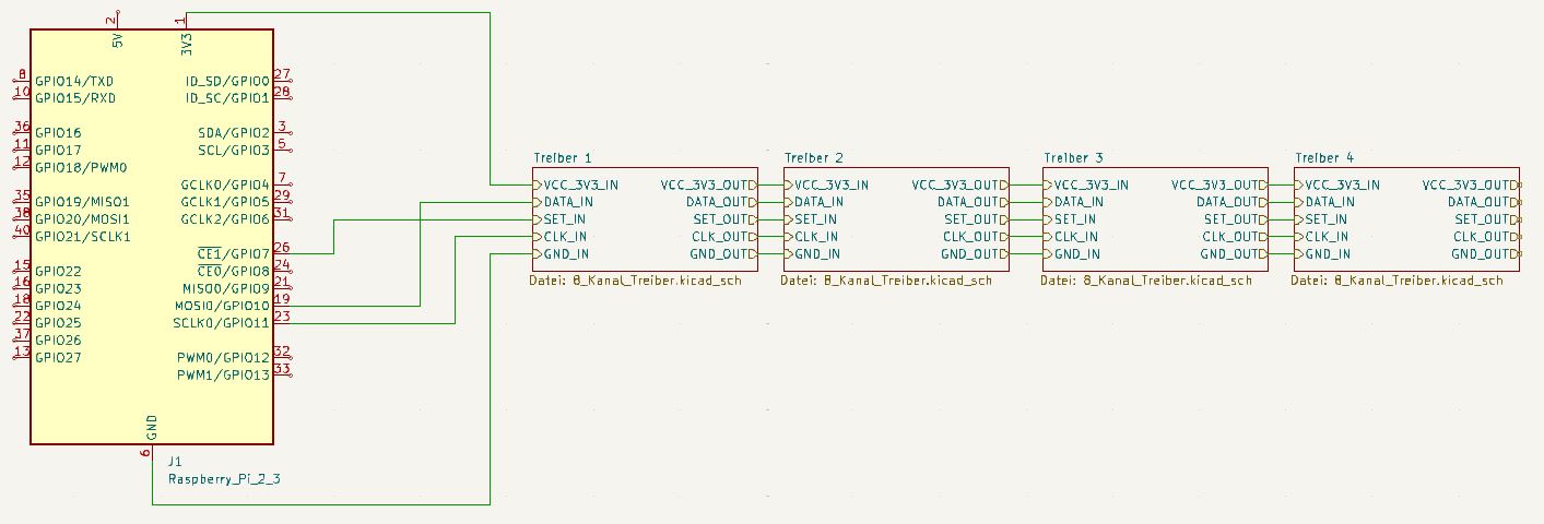
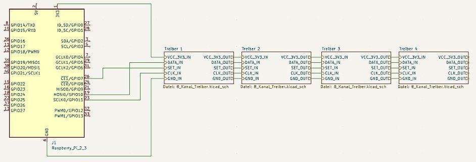
Schaltplan einer Treiberbeschaltung mit Raspberry Pi Anschlüssen
8 GPIO14/TXD 10 GPIO15/RXD 36 GPIO16 SDA/GPIO2 17 GPIO18/PWM0 5 SCL/GPIO3 7 GCLK0/GPIO4 29 GCLK1/GPIO5 35 GPIO19/MI501 31 GCLK2/GPIO6 26 CE1/GPIO7 15 GPIO22 CEO/GPIO8 24 GPIO24 MI500/GPIO9 22 GPIO23 MOSIO/GPIO10 17 GPIO25 SCLK0/GPIO11 32 PWM0/GPIO12 33 PWM1/GPIO13 27 ID_5D/GPIO00 28 ID_SC/GPIO1 21 MI500/GPIO9 19 MOSIO/GPIO10 23 SCLK0/GPIO11 32 PWM0/GPIO12 33 J1 Raspberry_Pi_2_3 GND Treiber 1 VCC_3V3_IN DATA_IN CLK_IN GND_IN Treiber 2 VCC_3V3_OUT DATA_OUT CLK_OUT GND_OUT Treiber 3 VCC_3V3_IN DATA_IN CLK_IN GND_IN Treiber 4 VCC_3V3_OUT DATA_OUT
in „Schieberegister mit UDN2981A an Raspberry PI“ · Mikrocontroller und Digitale Elektronik · · Schaltpläne
-
Datei
MAIN.C
#include <avr/io.h> void pwm_init (void); void EEPROM_write (unsigned short EEPROM_adresse, unsigned char EEPROM_data); unsigned char EEPROM_read (unsigned short EEPROM_adresse); int main(void) { pwm_init(); EEPROM_write(0x00,0xF0); EEPROM_read(0x00); OCR1A = EEDR; for(;;) { } } //End of main void pwm_init (void) { sbi(DDRD,PD5); sbi(PORTD,PD5); TCCR1A = _BV(WGM10) | _BV(COM1A1) | _BV(COM1A0) |_BV(COM1B1) | _BV(COM1B0); TCCR1B = _BV(CS11) | _BV(WGM12); } //End of pwm_init void EEPROM_write (unsigned
in „Problem mit Atmega-EEPROM“ · Mikrocontroller und Digitale Elektronik ·
-
Datei
led_dimmen.bas
'Hardware PWM fürs LED dimmen mit Timer 1 $regfile = "m32def.dat" $framesize = 32 $swstack = 32 $hwstack = 32 $crystal = 8000000 Dim A As Integer Dim B As Bit Dim C As Bit Dim D As Bit Config Pind.5 = Output Config Timer1 = Pwm , Pwm = 8 , Compare A Pwm = Clear Down , Prescale = 1 'Timer 1 einrichten: 8bit Modus Waitms 100 Do If Pind.3 = 1 Then Waitms 10 If Pind.3 = 1 Then A = 254 End If End If If Pind.2 = 1 Then Waitms 10
in „PWM Versuche mit Bascom“ · Mikrocontroller und Digitale Elektronik ·
-
PDF
Analyse_Federwiege.pdf
PWM (ident zu A3) • A7 Abhängig von Po� (rechts) 0-5V • A8 5V Abgefeilter 24-Pin IC • IC wird sehr warm, auch bei minimaler Stufe & ausgesteckten Motoren • Eingänge der PWMs aus 8-Pin IC auf der linken Seite (Pin 15 & Pin23) • PWM von 8-Pin IC ist auch auf Pin 11 & 12, solange kein Motor angesteckt ist • Ausgänge zum Motoren-Stecker auf der rechten Seite. 0V keine Veränderung bei Verstellung der Stufe Verbindung Motoren
in „Hilfe bei Reparatur von Federwiegen-Motor“ · Analoge Elektronik und Schaltungstechnik ·
-
 Bild
Bild
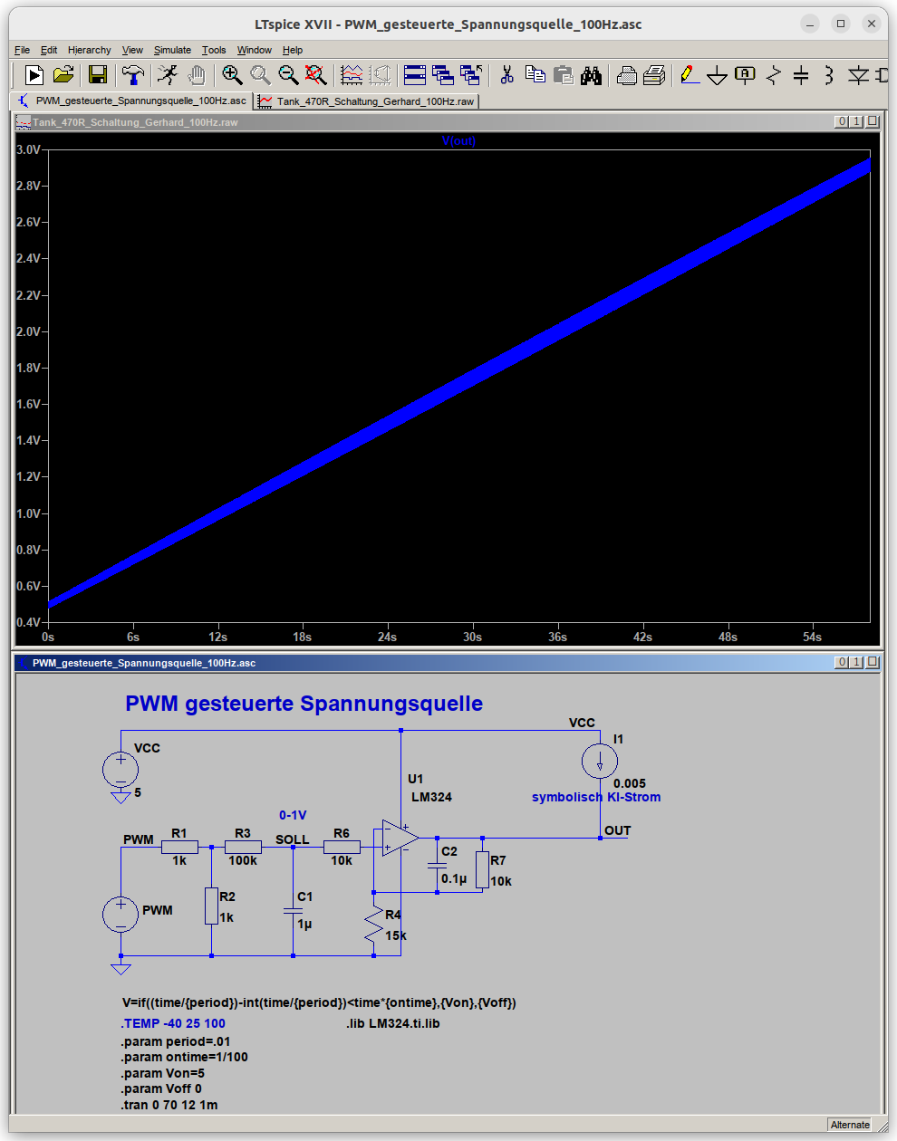
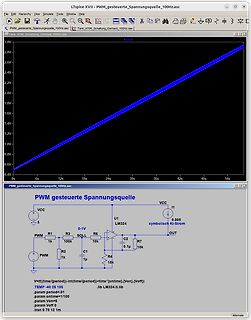
LTspice Simulation Schaltplan und Spannungsverlauf
LTspice - PWM_gesteuerte_Spannungsquelle_100Hz.asc File Edit Hierarchy View Simulate Tools Window Help PWM_gesteuerte_Spannungsquelle_100Hz.asc Tank 470R_Schaltung_Gerhard_100Hz.raw V[out] 3.0V 2.8V 2.6V 2.4V 2.2V 2.0V 1.8V 1.6V 1.4V 1.2V 1.0V 0.8V 0.6V 0.4V 0s 6s 12s 18s 24s 30s 36s 42s 48s 54s PWM_gesteuerte_Spannungsquelle PWM gesteuerte Spannungsquelle VCC I1 5 R1 R3 SOLL 0-1V U1 LM324 symbolisch 0.005 KI-Strom R2 C2 OUT 1k 100k 10k 1k C1 0.1u R4 15k 15k V=if((time/period)-int(time/period)*
in „Tankanzeige eines E36 mit Mikrocontroller Steuern“ · Fahrzeugelektronik · · Screenshots
-
Datei
CAN_ATMega-UVR-V5-1.bas
Chip Start Adc Config Porta = Input Config Pind.5 = Output Config Pind.4 = Output Config Timer1 = Pwm , Prescale = 8 , Pwm = 10 , Compare A Pwm = Clear Down , Compare B Pwm = Clear Down 'Config Timer1 = Pwm , Prescale = 64 , Pwm = 10 , Compare A Pwm = Clear Down , Compare B Pwm = Clear down Declare
-
PDF
A3967-Datasheet.pdf
FAULT SUPPLY DETECT VBB1 REF 20 1 ÷8 DAC SENSE + - RC 1 OUT1A 23 BLANKINGH 16 MIXED DECAY OUT1B 21 3 PWM TIMER STEP 10 DIR 11 R SENSE1 T 17 RESET 22 L I MS 1 12 N O R L MS 213 T R N 5 O VBB2 SLEEP 3 C ENABLE 15 VPF OUT2A 24 9 PWM TIMER OUT2B PFD 3 PWM LATCH 4 MIXED DECAY 2 RC2 + - DAC SENSE2 8 6 7 18 19
in „Vref Dual Step Motor Shield (Arduino) iteadstudio.com“ · Mikrocontroller und Digitale Elektronik ·
-
PDF
Datasheet_SIM800L.pdf
range 0 - 2.8 V ADC Resolution - 10 - bits Sampling rate - - 1.0833 MHz ADC precision 10 20 mV 4.14. PWM Table 30: Pin definition of the PWM Pin name Pin number Description SIM800L_Hardware_Design_V1.00 48 2013-08-20 Smart Machine Smart Decision PWM 26 PWM signal SIM800L provides a PWM which can be used
in „LM2596 an SIM800l“ · Mikrocontroller und Digitale Elektronik ·
-
Datei
Analog_komplett.c
{ // OC0A auf Ausgang DDRB = (1 << PB3 ); //OC0B auf Ausgang DDRB = (1 << PB4 ); // Zählerwert Top PWM PinB3 // OCR0A = 0x05F; // wie OCR0B // Zählerwert Top PWM PinB4 // OCR0B = 0x05F; //Wird durch die in der Schleife festgelegten werte ersetzt zb if Pin B1 -->>"123" //ANALOG-REGISTER uint16_t analog
in „Atmega644 PWM Timer0 OCROB / A -Problem“ · Mikrocontroller und Digitale Elektronik ·
-
Datei
top_MACHX02.vhd
is Port ( system_leds : out STD_LOGIC_VECTOR ( 7 downto 0 ); system_speaker : out STD_LOGIC; system_pwmSpeaker : out STD_LOGIC ); end entity; architecture Behaviour of top_MACHX02 is -- lattice oscillator OSCH primitive component OSCH generic ( NOM_FREQ: string ); port ( STDBY : IN STD_LOGIC; OSC : OUT
-
Datei
main.c
(&htim2, &sMasterConfig) != HAL_OK) { Error_Handler(); } sConfigOC.OCMode = TIM_OCMODE_PWM1; sConfigOC.Pulse = 0; sConfigOC.OCPolarity = TIM_OCPOLARITY_HIGH; sConfigOC.OCFastMode = TIM_OCFAST_DISABLE; if (HAL_TIM_PWM_ConfigChannel(&htim2, &sConfigOC, TIM_CHANNEL_3) != HAL_OK) { Error_Handler
in „STM32 SPI zu viele Clocks“ · Mikrocontroller und Digitale Elektronik ·
-
PDF
305000074A_radino_nRF8001.pdf
PCINT3 3 SCK 15 PB1 SPI-SCK (also connected to internal radio chip) GPIO; PCINT1 4 D6 6 PD7 GPIO; PWM A7 ADC10 5 IO10 10 PB6 GPIO; PWM; PCINT6; A10 ADC13 6 IO11 11 PB7 GPIO; PWM; PCINT7; UART-RTS 7 IO13 13 PC7 GPIO; PWM 8 D5 5 PC6 GPIO; PWM 9 A5 A5 PF0 ADC0 23 GPIO 10 Reset - Reset Reset of Atmega32U4
-
Datei
freqgen48.bas
Config Pinc.4 = Input Config Pinc.5 = Input Portc.3 = 1 Portc.4 = 1 Portc.5 = 1 '-------- Timer0 als PWM einrichten -------- Config Timer0 = Pwm , Prescale = 1 , Compare A Pwm = Clear Down , _ Compare B Pwm = Clear Down Enable Timer0 Start Timer0 '-------- Timer1 als Fast PWM einrichten -------- Tccr1a
in „Einstellbarer Frequenzgenerator für 0.12 Hz - 8 MHz mit Atmega 8 und Bascom“ · Projekte & Code ·
-
Datei
freqgen48.bas
Config Pinc.4 = Input Config Pinc.5 = Input Portc.3 = 1 Portc.4 = 1 Portc.5 = 1 '-------- Timer0 als PWM einrichten -------- Config Timer0 = Pwm , Prescale = 1 , Compare A Pwm = Clear Down , _ Compare B Pwm = Clear Down Enable Timer0 Start Timer0 '-------- Timer1 als Fast PWM einrichten -------- Tccr1a
in „Einstellbarer Frequenzgenerator für 0.12 Hz - 8 MHz mit Atmega 8 und Bascom“ · Projekte & Code ·
-
Datei
Programm.c
Definitionen-------------------------------------------------------- #define FullSpeed 1024 //Motor ein für PWM #define HalfSpeed 512 //Motor halbe Kraft #define OFF 0 //Motor aus für PWM #define UART_BAUD_RATE 9600 //UART Baudrate #define BufferMAX 100 //Buffer für Stringumwandlungen und Typumwandlungen #define
in „Roboter-Linienverfolgung mit P-Regler und Ausweichmodus“ · Mikrocontroller und Digitale Elektronik ·
-
Datei
Motorsteuerung.c
takt100ms; // Bit-Botschaft alle 100ms void motor(void); void lese_Eingang(void); void timer0(void); void pwm_generator(void); // Hauptprogramm ============================================================== int main() // Start des Hauptprogramms { timer0(); pwm_generator(); sei(); // SET_BIT(PORTD, PD5); //
in „Probleme mit PWM Erzeugung“ · Mikrocontroller und Digitale Elektronik ·
-
Datei
Motorsteuerung.c
takt100ms; // Bit-Botschaft alle 100ms void motor(void); void lese_Eingang(void); void timer0(void); void pwm_generator(void); // Hauptprogramm ============================================================== int main() // Start des Hauptprogramms { timer0(); pwm_generator(); sei(); // SET_BIT(PORTD, PD5); //
in „Probleme mit PWM Erzeugung“ · Mikrocontroller und Digitale Elektronik ·
-
Datei
data_receiver.vhd
clock, 8MHz rx_data : in std_logic; -- DMX512 data chn_sel : in std_logic; -- select DMX512 channels pwm_data : out std_logic_vector(7 downto 0); -- parallel DMX data pwm_adr : out std_logic_vector(7 downto 0); -- address for PWM RAM page : out std_logic; -- RAM page selector trigger : out std_logic; -
-
Datei
ledctl.asm
r18 ; Speicher fuer Schwellwert .def demcnt = r19 ; Zeahler fuer Demoprogramm .def pwmcnt = r20 ; PWM Zaehler .def pwmsig = r21 ; Update Signal .equ t0in = 205 ; Init wert Timer .equ pwmmax = 0x40 ; Anzahl Schritte fuer PWM ;---------------------------------------------------------------------------
-
Datei
WO_ini.asm
Wobbelgenerator-Zusatz ; Bernhard.Erfurt@gmx.de ; 12/2006 ; ; ; Anschlussbelegung PINS ; ; PB0 ==> AUSGANG PWM für X-Eingang OSZI ; PB1 ==> ; PB2 ==> ; PB3 ==> ; PB4 ==> ; PB5 ==> ; PB6 ==> Quarz ; PB7 ==> Quarz ; ; PC0 ==> ; PC1 ==> ; PC2 ==> ; PC3 ==> ; PC4 ==> ; PC5 ==> ; ; PD0 ==> ; PD1 ==> ; PD2 ==> EINGANG
in „Wobbelgenerator Erweiterung für Oszilloskop 1HZ...20MHz“ · Mikrocontroller und Digitale Elektronik ·
-
Datei
freqgen88_org.bas
Config Pinc.4 = Input Config Pinc.5 = Input Portc.3 = 1 Portc.4 = 1 Portc.5 = 1 '-------- Timer0 als PWM einrichten -------- Config Timer0 = Pwm , Prescale = 1 , Compare A Pwm = Clear Down , _ Compare B Pwm = Clear Down Enable Timer0 Start Timer0 '-------- Timer1 als Fast PWM einrichten -------- Tccr1a
in „Einstellbarer Frequenzgenerator für 0.12 Hz - 8 MHz mit Atmega 8 und Bascom“ · Projekte & Code ·
-
Datei
zusammenfuehrung_tabelle.asm
equ key_port = PORTD .equ key_ddr = DDRD .equ led_port = PORTB .equ led_ddr = DDRB //Zuweisungen für PWM .def temp = r17 .def PWMCount = r19 .def ocr_r = r20 ; Helligkeitswerte der LED R/G/B .def ocr_g = r21 .def ocr_b = r22 .def level_r = r23 .def level_g = r24 .def level_b = r25 .equ T0 = 0 .equ T1 =
in „Mega8 Assembler RGB Fader“ · Mikrocontroller und Digitale Elektronik ·
-
Datei
Terminator_LED.c
// F_CPU = 1MHz, Prescaler 16 -> 244 Hz TCCR1 = (1<<CS12) | (1<<CS10); // Prescaler 16 GTCCR = (1<<PWM1B) | (1<<COM1B1); // non inverted PWM while(1) { // reboot for (i=0; i<32; i++) { OCR1B = pgm_read_byte(&pwmtable[i]); j = rand_range(100, 500); delay(j); OCR1B = 0; j = rand_range(100, 1000); delay(j); } // operation, scanning environment for (i=0; i<6; i++) { pwm_up_down(32, 100); } // malfunction, flickering for (i=0; i<256; i++) { j = pgm_read_byte(&flicker_light[i]); OCR1B = pgm_read_byte(&pwmtable[j]); _delay_ms(100); } // off time OCR1B = 0; for (i=0; i
in „Terminator-LED“ · Projekte & Code ·
-
Datei
Terminator_LED.c
// F_CPU = 1MHz, Prescaler 16 -> 244 Hz TCCR1 = (1<<CS12) | (1<<CS10); // Prescaler 16 GTCCR = (1<<PWM1B) | (1<<COM1B1); // non inverted PWM while(1) { // reboot for (i=0; i<32; i++) { OCR1B = pgm_read_byte(&pwmtable[i]); j = rand_range(100, 500); delay(j); OCR1B = 0; j = rand_range(100, 1000); delay(j); } // operation, scanning environment for (i=0; i<6; i++) { pwm_up_down(32, 100); } // malfunction, flickering for (i=0; i<256; i++) { j = pgm_read_byte(&flicker_light[i]); OCR1B = pgm_read_byte(&pwmtable[j]); _delay_ms(100); } // off time OCR1B = 0; for (i=0; i
in „Xenon Zündeffect mit LED von 2009“ · Analoge Elektronik und Schaltungstechnik ·
-
Datei
PinTemplateVirtual.ino.elf.txt
ldi r30, 0x80 ; 128 342: fa e0 ldi r31, 0x0A ; 10 // Timer B Setup loop for TCB[0:3] do { // 8 bit PWM mode, but do not enable output yet, will do in analogWrite() timer_B->CTRLB = (TCB_CNTMODE_PWM8_gc); 344: 37 e0 ldi r19, 0x07 ; 7 // Assign 8-bit period timer_B->CCMPL = PWM_TIMER_PERIOD; 346: 2f ef
in „Buchempfehlung C++ und MCUs“ · Mikrocontroller und Digitale Elektronik ·
-
 Bild
Bild
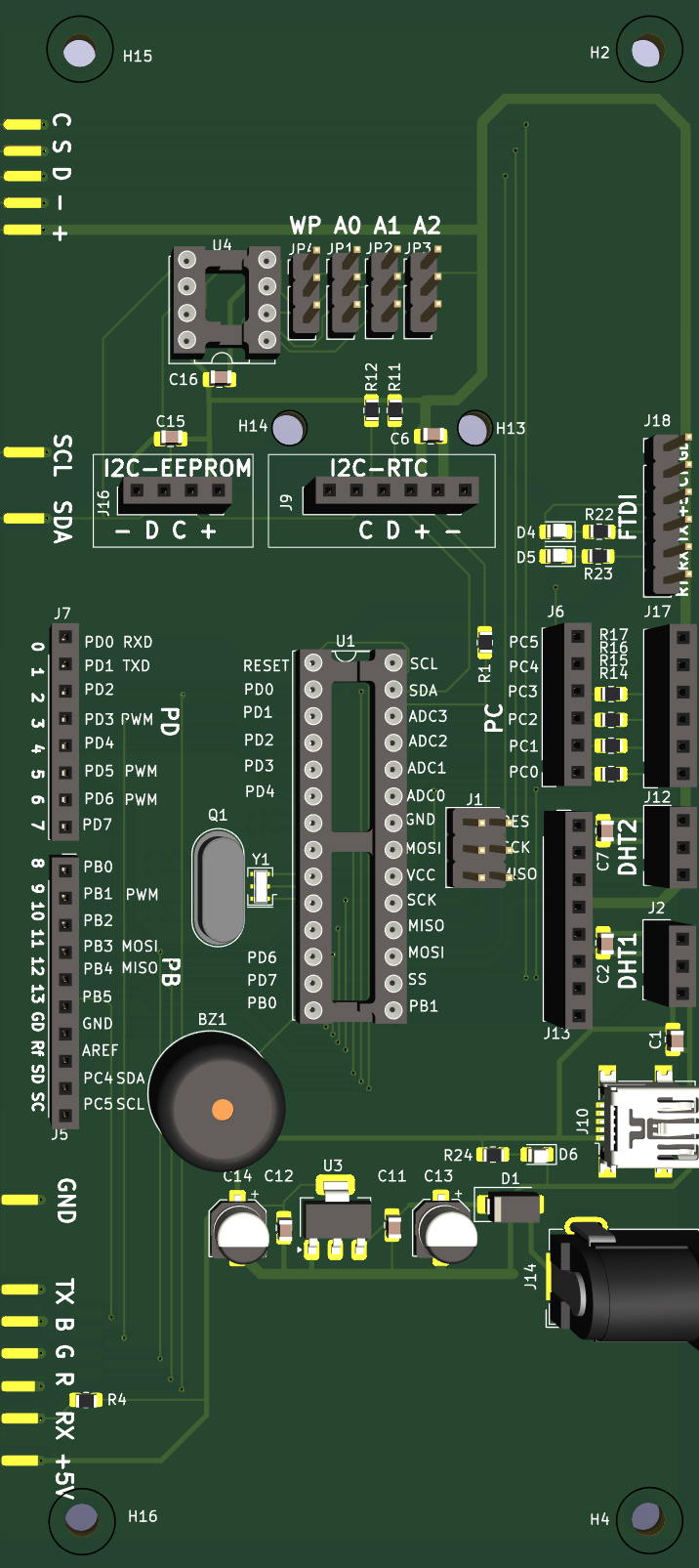
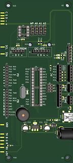
Leiterplatten-Layout eines Mikrocontroller-Boards
PC3 PC2 PC1 PC0 R16 R14 R15 J12 DHT2 C7 DHT1 C2 J2 J13 PD0 RXD PD1 TXD RESET PD0 SCL PD2 ADC3 PD3 PWM SDA PD4 ADC2 PD5 PWM ADC1 PD6 PWM PD7 PB1 PWM MISO PB2 MOSI PB3 MOSI SCK PB4 MISO USB PB5 SS GND GND PD7 PB0 Y1 Q1 BZ1 C14 C12 U3 R24 D6 J10 C11 C13 D1 J5 AREF RD SC GND J14 TX B G R RX +5V R4 PB0 H16
in „Arduino: page-write in I2C eeprom verliert sporadisch ein Byte“ · Mikrocontroller und Digitale Elektronik · · Layouts
-
Datei
servo.h
Bibliothek für Anschluss zweier Servos an ATMega16 ******** Diese bibliothek Steuert zwei Servos, deren PWM eingang an die Pins OC1A und OC1B eines Atmega 16 angeschlossen sind. Zuerst ist init_servo(void) auszuführen, welche alle nötigen Einstellungen am Timer 1 vornimmt, und die Servos in Mittelstellung
in „OCR1A lässt sich nicht schreiben?“ · Mikrocontroller und Digitale Elektronik ·
-
Datei
config.h
: Motor 1-6 = 10-bit hardware PWM Motor 7-8 = 8-bit Software PWM Servos = 8-bit Software PWM if deactivated: Motor 1-4 = 10-bit hardware PWM Motor 5-8 = 10-bit Software PWM Servos = 10-bit Software PWM */ #define HWPWM6 /***********
in „Problem mit meinem Projekt (Quadrocopter)“ · Mikrocontroller und Digitale Elektronik ·
-
PDF
kendryte_datasheet_20181011163248_en.pdf
frequency or period • PWM timers can be configured to synchronize with other PWM timers or modules • PWM timers can be in phase with other PWM timers or modules • Timer count mode: up, down, or up and down in a loop • Use the prescaler to change the rate of the PWM timer clock (PT_clk). Each timer has its own prescaler, configured by PWM_TIMERx_PRESCALE in the register PWM_TIMER0_CFG0_REG. The PWM timer is incremented or decremented at a slower rate depending
in „RiscV Maixduino“ · Mikrocontroller und Digitale Elektronik ·
-
 Bild
Bild
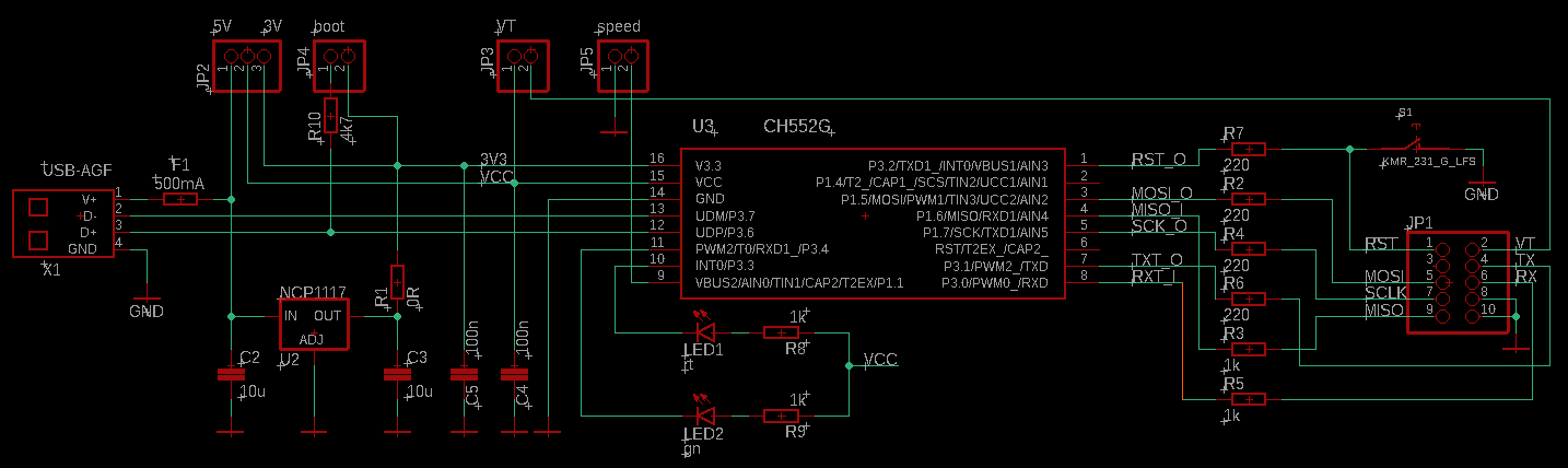
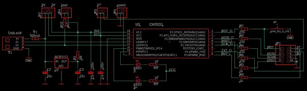
Schaltplan mit CH552G Mikrocontroller
5V 3V boot /T speed JP2 JP4 JP3 JP5 U3 CH552G P3.2/TXD1/INT0/VBUS1/AIN3 1 P3.4/PWM2/TO/RXD1/JP3.4 10 P3.6/UDP/P3.6 12 P3.7/SK/TXD1/AIN5 4 P3.0/PWM0_TXD 9 P3.1/PWM2_INT/CAP2/TXD 8 P1.7/SK/TXD1/AIN5 5 P1.6/MIS0/PWM1/TIN3/UCC2/AIN2 6 P1.4/T2/CAP1/SCK/TIN2/UCC1/AIN3 2 VCC 15 GND 14 V3.3
in „uC für 0,20€ CH552 / CH554 von WCH Billig Micro mit USB Funktion, Chip vorstellung“ · Mikrocontroller und Digitale Elektronik · · Schaltpläne
-
Datei
motor_test.c
#include <avr/interrupt.h> #include <util/delay.h> #include <stdlib.h> #define MOTOR OCR0 // MOTOR PWM OUTPUT #define ARRAY_SIZE(x) (sizeof(x) / sizeof(*x)) // Length of Array uint8_t speed_normal[5] = {40, 60, 80, 100, 120}; // PWM steps uint8_t random_speed = 0; // current step uint8_t lasttime = 0; // period of last step volatile uint8_t cnt=0; int main (void) { DDRB = _BV(PB3); // MOTOR PWM as output // Non inverting 8 bit phase correct PWM (MAX=0xFF), no prescale TCCR0 = _BV(COM01) | _BV(WGM00) | _BV(CS00); // timer 1 TCCR1B = _BV(CS11) | _BV(CS10); // clk/64 TCNT1 = 34286; // preload
in „Timer/PWM Problem an ATmega16“ · Mikrocontroller und Digitale Elektronik ·
-
Datei
v24.ino
wird geprüft ob der PWM Wert höher oder gleich 255 ist digitalWrite (l, LOW); // ist er höher oder gleich dann wird die LED ausgeschaltet ch = 1; // ch wird auf den LED Wert gesetzt } } delay (5); if (digitalRead (th) == HIGH
in „Arduino Tocuhsensor LED "Dimmen"“ · Mikrocontroller und Digitale Elektronik ·
-
Datei
top_MACHX02_SAB600.vhd
-- this top level vhd used the -- SAB0600_4BitPWM.vhd made by lothar MIller form Okt.2012 -- https://www.mikrocontroller.net/attachment/highlight/158318 library ieee; use IEEE.STD_LOGIC_1164.ALL; use IEEE.NUMERIC_STD.ALL; --LIBRARY lattice; --USE lattice.components.all
-
Datei
Regendusche3.cc
/OCR0 = 255 ; // rot //---------------------------------------------------------------------- void pwmInit() { TCCR0 = 0b01100001 ; // Timer R Prescaler 1024 / Phase Correct PWM TCCR1A = 0b10100001 ; // Timer G Prescaler 1024 / Phase Correct PWM TCCR1B = 0b00000001 ; // Timer B Prescaler 1024 / Phase Correct PWM TCCR2 = 0b01100001 ; // Timer DimmerPrescaler 1024 / Phase Correct PWM TIMSK = 0b00000001; } //---------------------------------------------------------------------- void reset_all() { tropenregen_an
in „Timer und Resetprobleme mit Mega16“ · Mikrocontroller und Digitale Elektronik ·
-
Datei
Sinus_Kondensatormotor_20200321e.ino
wertvor; int uspg; int zspg; int usin; int zsin; byte zahl = 1; void setup() { // Configure Timer 1 for PWM @ 25 kHz. TCCR1A = 0; // undo the configuration done by... TCCR1B = 0; // ...the Arduino core library TCNT1 = 0; // reset timer TCCR1A = _BV(COM1A1) // non-inverted PWM on ch. A | _BV(COM1B1) // same on ch; B | _BV(WGM11); // mode 10: ph. correct PWM, TOP = ICR1 TCCR1B = _BV(WGM13) // ditto | _BV(CS10); // prescaler = 1 ICR1 = 320; // TOP = 320 // Set the PWM pins as output. pinMode( 9, OUTPUT); pinMode(10, OUTPUT); analogWrite25k(upin, 0); analogWrite25k
in „Arduino Kondensatormotor Drehzahlsteuerung“ · Analoge Elektronik und Schaltungstechnik ·
-
PDF
XR1151.pdf
The the amplified and compensated difference between device features fixed frequency, current mode PWM the feed- back voltage on the FB pin and the control for excellent line and load regulation. The low internal reference voltage of 0.6V. If the control R ds(on)NMOS switch enables the device to maintain
-
PDF
JSN-SR20-Y1-2-W100.pdf
www.manorshi.com 2 MECHANICAL DRAWING FUNCTION OUTPUT DESCRIPTION Output method Mode bit resistance Remarks No. PWM pulse width output Floating Factory default Modle 0 Modle 1 UART automatic output 47KΩ UART controlled output 120KΩ Instruction 0X5 Modle 2 5 PWM automatic output 200KΩ Cycle 200MS Modle 3 Modle 4 Low
in „Fragen zum US Sensor JSN-SR20-Y1“ · Mikrocontroller und Digitale Elektronik ·
-
Datei
mc9s12xdp512.c
/* VREG_3V3 - Autonomous Periodical Interrupt Trimming Register; 0x000002F3 */ volatile PWMESTR _PWME; /* PWM Enable Register; 0x00000300 */ volatile PWMPOLSTR _PWMPOL; /* PWM Polarity Register; 0x00000301 */ volatile PWMCLKSTR _PWMCLK; /* PWM Clock Select Register; 0x00000302 */ volatile PWMPRCLKSTR _PWMPRCLK; /* PWM Prescale Clock Select Register; 0x00000303 */ volatile PWMCAESTR _PWMCAE; /* PWM Center Align Enable Register; 0x00000304 */ volatile PWMCTLSTR _PWMCTL; /* PWM Control Register; 0x00000305 */ volatile
in „ADC Prog Problem Freescale S12X Familie“ · Mikrocontroller und Digitale Elektronik ·