-
Thread
Digikey Sammelbestellung
Dann bin ich auch mal dabei: 25x MSP430F2012TRSAT Teilenummer: 296-19735-1-ND 25x TL431AIDCKR Teilenummer: 296-17864-1-ND joergsommer(at)gmx.de
zu tun. Leider, so wie ich Großkonzerne kenne, bewegen die sich keinen Zentimeter. Das stärkste As im Ärmel, da ich dort ja viel bestelle ist die Drohung zu Mouser zu wechseln. Ob ich diese Karte jedoch ausspielen möchte weis ich noch nicht. LG Michael
-
Thread
Notch-Filterbaustein gegen 50 Hz Brummen
hast du schonmal 2) und misst zudem kapazitiv mit einem ebenfalls kapazitiven bezugspotenzial. df1as schrieb im Beitrag #2209889: > Ist die 50-Hz-Amplitude so groß, dass sie den Eingangsverstärker in die > Begrenzung bringt? ich weiß ehrlich gesagt noch nicht genau, wie groß die 50Hz amplitude
Filter verwenden - kommt halt auf das unbekannte Drumrum an. http://pdfserv.maxim-ic.com/en/an/AN431.pdf
-
Thread
avr adc streuung ausgleichen
The AVCC pin on the device should be connected to the digital VCC supply voltage via an LC network as shown in Figure 23-9 on page 213. Es ist ja jedem selbst überlassen ob er den Filter einbaut oder nicht. Ein AVR wird auch ohne Abblockkondensator zw. VCC und GND laufen, trotzdem baue ich den ein
Signifikantes am angezeigten Ergebnis ändern würde) ``` ADC faktor 127 7388797 In: 14.319 V … 14.431 V Mess: 14319.000 mV … 14431.000 mV 255 7374343 In: 28.694 V … 28.806 V Mess: 28694.000 mV … 28806.000 mV 511 7367157 In: 57.444 V … 57.556 V Mess: 57444.000 mV … 57556.000 mV 767 7364769
-
Thread
Wie wird der Takt einer RTC abgeglichen?
leistungsfähigen Zähler zulegen? Mein Ding: http://www.mino-elektronik.de/fmeter/fm_software.htm#bsp_G431
address 0Dh. Frequencies of 32.768 kHz (default), 1.024 kHz, 32 Hz, and 1 Hz can be generated for use as a system clock, microcontroller clock, input to a charge pump, or for calibration of the oscillator. CLKOUT is an open-drain output and enabled at power-on. If disabled it becomes high-impedance.
-
Thread
Diskreter Schaltregler
"diskrete Schaltung". OK, die besseren diskreten (sic!) Schaltnetzteile enthalten typisch einen TL431 im Regelkreis. Das ist nicht ganz ein OPV. Aber doch schon nahe dran. Aber gerade die 12V-Teile kann man prima auch mit Z-Diode bauen. BTST.
Punkte detailliert erläutert. http://www2.produktinfo.conrad.de/datenblaetter/125000-149999/130228-as-01-de-PWM_Schaltnetzteil.pdf Ich hoffe du hast keine Angst vor OV's Grundlagen schaden nie ;-) Beste Grüße
-
Thread
STM32F103C8T6 - Fälschung von ST bestätigt
von Mouser für 13,40€ (G431) bzw. 11,50€ (alle anderen) zzgl. Versand. Netterweise haben alle diese Boards einen ST-Link V2.1 onboard. Richard K. schrieb im Beitrag #6126714: > Mein Posteingang quillt zwar gerade über, aber
weiter interpretiert? Und das ist dann nur einer von vielen Werten: [c] // This is the ROM TABLE as defined in the Cortex-M reference manual // Please note a non conforming implementation might differ from this // but still be a valid ROM TABLE when being parsed as being a ROM TABLE. // Meaning,
-
Thread
Spannungsmessung an LIPO Akkus
es mal mit Worten von jemand anderen zu sagen, mir glaubst du ja eh nicht: The ADC is specified as having a 100 MΩ (that is MegaOhm) input impedance. However, this seems somewhat suspicious to me. Together with the fact that there is no analog input leakage specified, I would guess that this is
gab wenig zufriedenstellende Ergebnisse aufgrund der 1:7.67. Deshalb habe ich schnell mit einem TL431 eine 10V ref gebastelt die ich mit meinem Fluke einstelle. Der tiny1626 macht beim Einschalten eine Messung. Und wenn er auf allen 8 inputs eine ähnliche Spannung im Bereich 10.00V +-200mV sieht,
-
 Bild
Bild
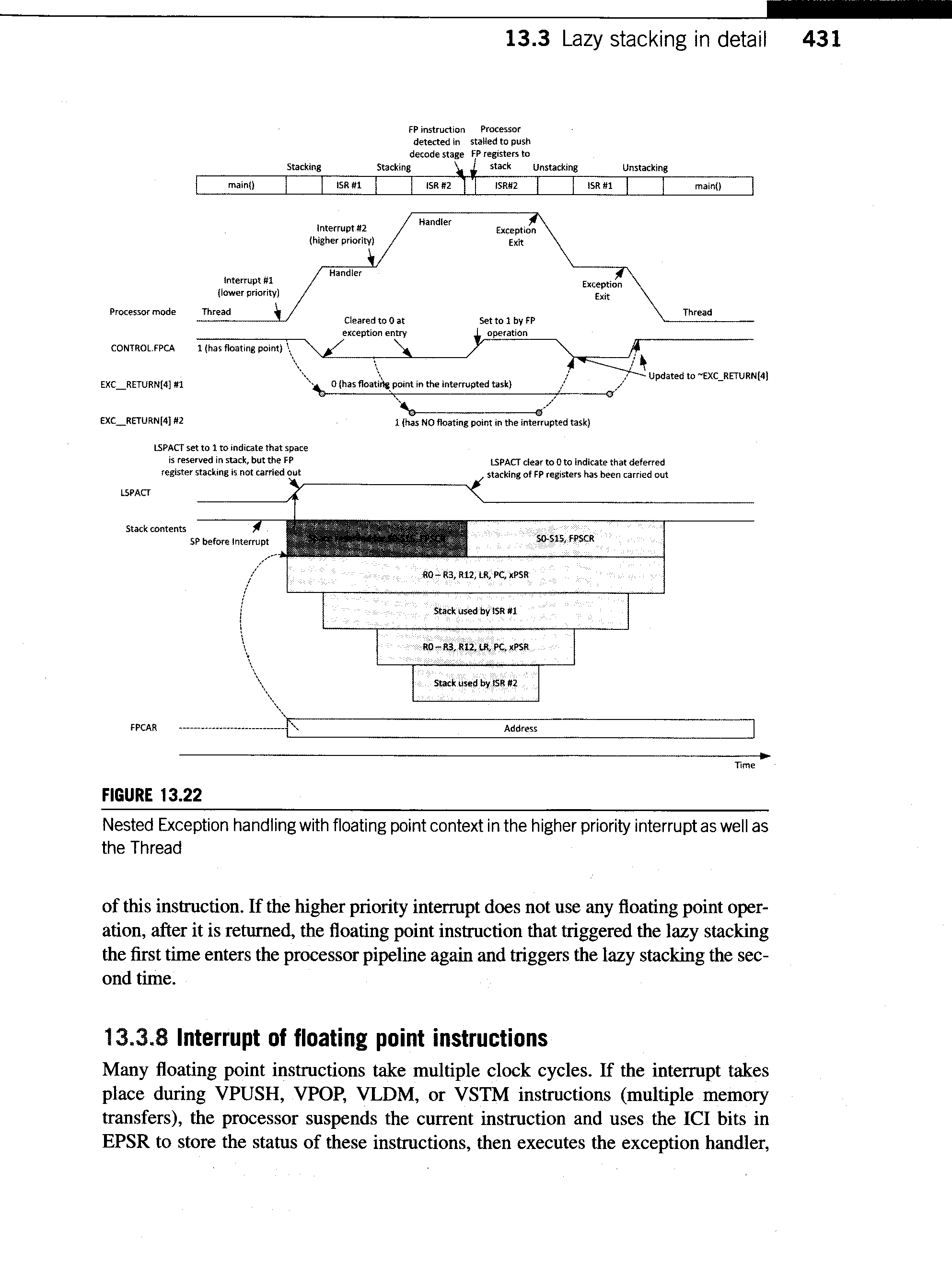
Diagramm zum Nested Exception Handling mit Floating Point Context
13.3 Lazy stacking in detail 431 Stacking ISR #1 ISR #2 Unstacking Unstacking main() main() Interrupt #2 (higher priority) Handler Exception Exit Interrupt #1 (lower priority) Handler Exception Exit Processor mode Thread Thread CONTROL
-
Thread
Das Innenleben von Transistoren und Operationsverstärkern
noch-zu-tun-Liste: LH0075 LH0070 (alt) TDA1034 ISO120 OPA512 LT1019 LT1029 U243B DAC706 LM35 LM234 TL431 NE602 AD565 (ohne A) DS1820 oder DS1821 LM10 :) Viele Grüße, Richard
colleges worldwide. You can easily rely on us whenever you want any assistance with your homework as we are always available for you. Just make a call or drop an email for us to reach you as soon as possible. https://www.greatassignmenthelp.com/sg/
-
Thread
Suche 3,3V und 5V Spannungsregler mit sehr geringem Ruhestrom
> das > Problem ist echt die Referenzspannungsquelle (hier eine rote LED) echte "ROTE" LEDs (GaAsP mit 1,6V 660nm) gibts leider nicht mehr. Die heutigen hochoptimierten "hellroten" LEDs sind bei weitem weniger Temperaturstabil. Gruß Anja
fileId=db3a304412b407950112b41887722615 Da ich deutlich unter VgsMax bleibe, keine Zenerdiode/TL431 und Angstwiderstand nötig. Ich konnte jetzt mit vielen anzuzeigenden Nullen/Achten 1,9mA messen, der Spannungsabfall ist da tatsächlich zu vernachlässigen. Ich messe auf das mV keinen Unterschied
-
Thread
FPGA-Funktion I2C-Slave VHDL
- line 267: I don't assert TX_empty always. Only when Master wants to read. This way I can use it as a handshake signal, to initiate a read into wr_buf_q (tx_data). - line 283: removed the check for tx_empty = '1' - line 431: I think a little bug with tx_data and wr_buf_q You can search for fho
-
Thread
uC from Scratch
abweichen womit VDDA verbunden wird. 4. RST und BOOT Pins nach Datenblatt beschalten, beim STM32G431 muss man diese z.B. nicht mal beschalten, da sind die optional und können per Programmer und Firmware gesetzt/aktiviert/gesteuert werden. Beim den STM32F103 ist das nicht so. 5. Niemals die SWD Pins
ATmega) Symbole bereits in der Standard-lib haben. In dem angehängten Bild siehst du wie ich den STM32G431 für eine rein digitale Schaltung mit interner VDDA-Referenz beschaltet habe. Die Probleme fangen erst so richtig an wenn du das Teil programmieren musst, wie viel Erfahrung ist denn da vorhanden
-
Thread
Pollin - Receiver-Mainboard mit Twin DVB-[T,C] Tuner, NXP PNX8950EH
'!<\r><\n> FEN_Init: Inititalization via RegisterDevice: using Context=257 as index (dll loaded by fe_loader)!<\r><\n> +CFeProbe::run[2]<\r><\n> CFeProbe::run[2]: probing frontend 'fe_tda10023'!<\r><\n> FEN_Init: Inititalization via RegisterDevice: using Context=258 as index
NEELIX implemented a small security here still, that is called if the Stick is not taken, the box as starts as usual, without the SOTClienten.Weiter is to be said still, that the SOTClient starts always the FTP & the VNC server with, what is at the beginning absolutely advisable. As further case forecastle
-
Thread
Internet Anschluss unzuverlässig
15.258 ms 15.503 ms 15.326 ms 7 ae59.xcr1.fix.cw.net (195.2.20.225) 15.131 ms 15.865 ms 15.431 ms 8 as6830-gw-xcr1.fix.cw.net (195.2.22.210) 15.243 ms 15.724 ms 14.440 ms 9 de-fra04d-rc1-ae-43-0.aorta.net (84.116.130.101) 23.260 ms 25.296 ms 28.772 ms 10 de-dus01a-rd02-ae-1-0.aorta.net
-
Thread
Induktiver Positionssensor - Fragen dazu
gemalten Schaltungen mit irfanview zu bw = black & white = 1 Bit pro Pixel. Beschneiden ggf., Save as bmp, Open with PAINT, putzen, radieren..., Save as png. Ich kann ja auch Fotografie, komplett!, techn., künstl., analog und Klapperkiste. Ich bin auch garnicht traurig, Balltreter, Auto-Dreaming
schon erstmal einen rudimentären Schaltplan gezeichnet. Die Spannung werde ich an Aref mit einem TL431 legen. Und bei der Gelegenheit fällt mir gleich auf, dass ich den Stromsensor (ACS712) vergessen habe.
-
Thread
RL78/G14 Renesas - Free Linux Toolchain
(94403ec ist ein Link auf https://github.com/Freetz-NG/freetz-ng/commit/94403ec7012aa08b7d80ebf4cd431af24f64f487)
= 391, duplicates = 0 */ >ls -l | grep '\-rwx' -rwx------ 1 mw users 3239 Jan 5 11:24 as -rwx------ 1 mw users 72050632 Jan 8 14:59 cc1 -rwx------ 1 mw users 78402456 Jan 8 14:59 cc1plus -rwx------ 1 mw users 1742272 Jan 8 14:58 collect2 -rwx------ 1 mw users 3239 Jan 5
-
Thread
Einweg-Vape erforschen :-)
PS63020 = TPS63020 4A 1,8-5,5V buck-boost regulator U2 kann ich nichts lesen = ? U3 Aufdruck: 431 = TL431? U4 Aufdruck: 5023X = ?
des eingebauten chips ( der normalerweise zur heizwendel geht) angegeben: load voltage, Charging as a power supply pin mit einem spannungsbereich bis zu 6v- Operating chracteristics: im Ladebetrieb 4,5 bis 6V und ein Ladestrom von 120 ma wenn an AT irgend was zwischen 2,8 und 4,1 v anliegt. Sieht
-
Thread
ItoA mit Uint64_t
deine Lib gern ausprobieren. Stehe jedoch vor dem Problem, dass ich nicht weiß wo ich den Eintrag in AS machen soll? Im Optionsfeld -I funktioniert es nicht.
Es gibt keinen Grund, warum das nicht gehen sollte. Ist ja c++ header only. In | AS| SolutionExplorer(*) | Toolchain |AVR-GNU_c++_complier | Directories | mit dem Icon |+| einen neuen Pfad anlegen mit dem Icon |...| Datei Explorer öffnen und den Include Pfad suchen und eintragen
-
Thread
Projektleiter wider Willen
auf administrativer und know how Ebene was du auch ansagst. "Ask me any question, i will support you as much as ..." Im unwahrscheinlichen Fall das es zu einem marktfähigen Produkt kommt (was ich bei der Konstellation für ausgeschlossen halte) muss du es halt sportlich sehen und einen Fehler eingestehen
interessiert ihn >nicht. Läuft und die Welt ist für ihn in Ordnung... Nobody cares how it works as long as it works.
-
Thread
Arduino Kondensatormotor Drehzahlsteuerung
muss dem Arduino auf jeden Fall mitteilen, wenn die Zwischenkreisspannung 750V überschreitet. TL431 und Optokoppler. LG old.
muss dem Arduino auf jeden Fall mitteilen, > wenn die Zwischenkreisspannung 750V überschreitet. > TL431 und Optokoppler. [c] if((digitalRead(zwkpin)) == HIGH){zwkist = micros(); // Überspannungsabschaltung Zwischenkreis if(zwkist - zwkstart > zwkvz){zwk = HIGH;}} else{zwkstart =
-
 Bild
Bild
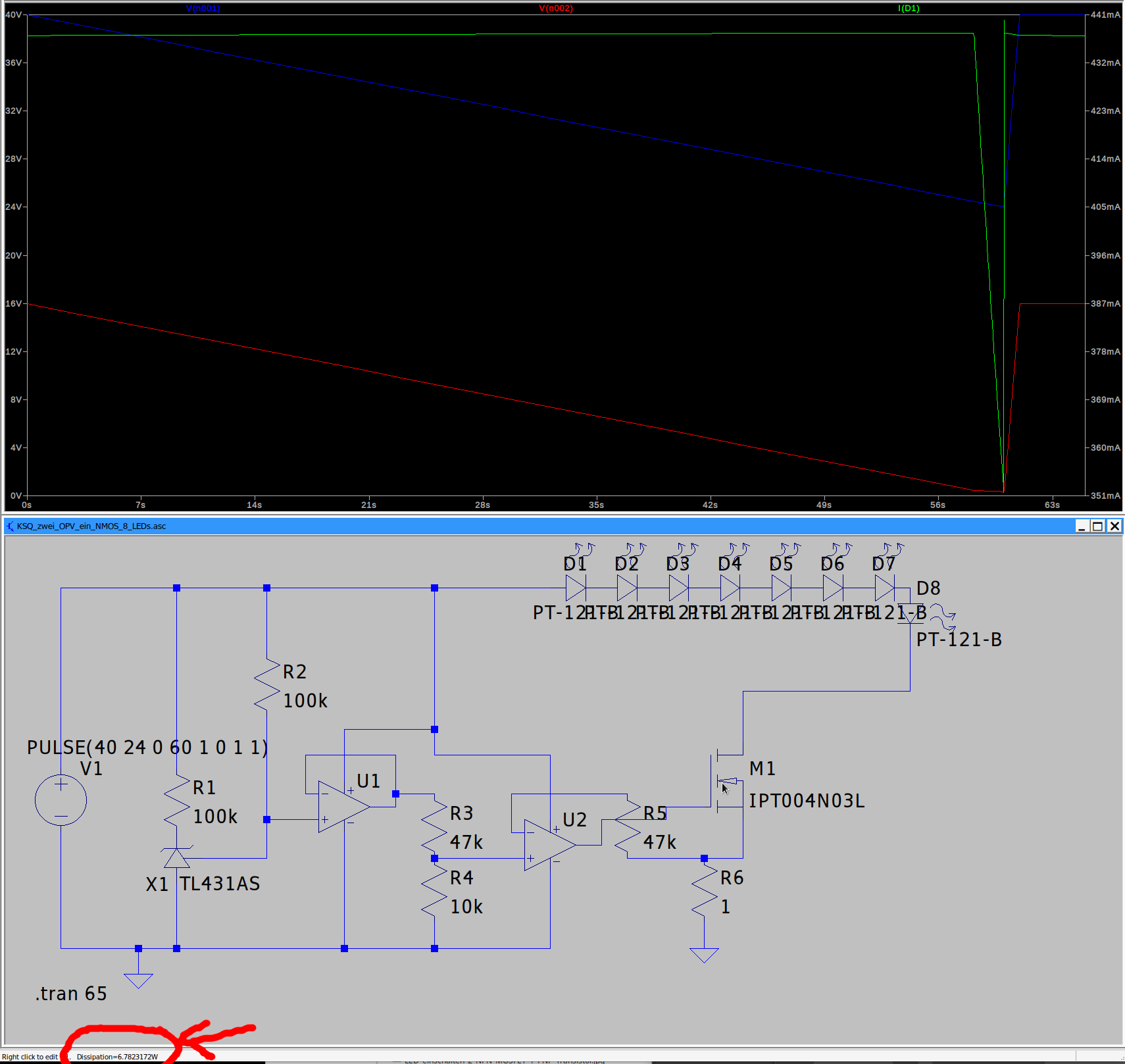
Simulation eines LED-Treiberschaltkreises mit Oszillogramm
KSQ_test_OPV_sim_NMOS_6_LEDs.asc R2 100k R1 100k V1 PULSE(40 24 0 60 1 0 1 1) U1 R3 47k R4 10k X1 TL431AS D1 bis D7 PT-121-B D8 PT-121-B U2 R5 47k R6 1 IPT004N03L L.tran 65

-
 Bild
Bild
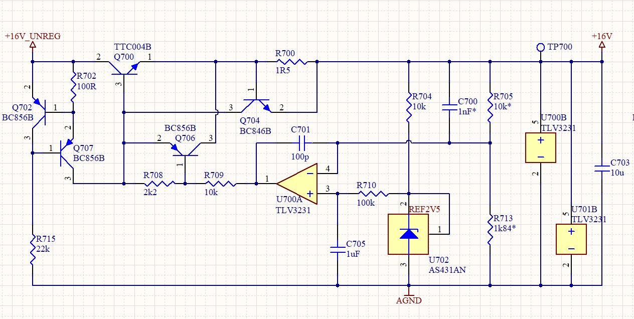
Schaltplan einer Spannungsreferenzschaltung
BC56B,3,1,R715,22k,3,R708,2k2,2,Q706,BC856B,3,R709,10k,4,U700A,TLV3231,100p,3,R710,100k,REF2V5,1,U702,AS431AN,3,AGND,C705,1uF,R704,10k,C700,1nF*,R705,10k*,1,R5,1R5,TP700,+16V,5,U700B,TLV3231,+,2,C703,10u,5,U701B,TLV3231,+,2
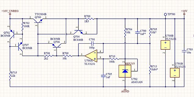
-
Thread
Schaltnetzteil defekt? Wäschetrockner AEG Electrolux
Drum is working now. All diagnostis pass, but I I start normal drying cycle, drum start rotating as normal, but Drying program finish after less then 1 minute as OK. Of course clothes are not dried :-( Diagnostic program 6 finish similarly early as normal drying cycle - Pass Manual write about
. Auf dem unscharfen Photo von eben nicht erkennbar, aber oben auf PIC0008: U8 ist beschriftet mit 431A1, also ein TI TL431 (http://www.ti.com/lit/ds/symlink/tl431.pdf). Wird damit hier eine (einstellbare) Z-Diode realisiert? Mir ist noch aufgefallen: D19 ist nicht bestückt. *Ich* habe sie auch nicht
-
Thread
STM32 - Low Level Library Dokumentation
aus dem verlinkten getting started: click Run > Debug As > STM32 MCU C/C++ Application. Man muss eine Launch config erstellen, das macht ein STM Plugin.
an. Lösche die mal, und klicke dann mit der rechten Maustaste auf den Projektnamen und dann "Debug As...", dann auf "STM32 Cortex-M C/C++ Application". Die IDE legt dann eine neue Konfigurationsdatei an.
-
Thread
Mein neues LieblingsnetzteiL? OWON SPM6103
will es nicht mal haben, da mir der Schaden viel zu groß wäre, wenn es mal kaputt geht. Für das,w as da die Reparatur kostet, kann ich auch einfach eine neues modernen kaufen mit viel mehr Leistung und ausreichend stabiler Spannung für 99,99 % aller Fälle. Und zu Deiner Frage "Wo sind die Oszi-Bilder
Schwächen Wenn ich also eine Schaltung mit 5V und es zu unerwarteten Problemen kommt, Kurzschluss ,w as auch immer, dann ist das Risiko bei einem solchen Netzteil groß, das es den Controller etc himmelt, weil auch bei 5V durch den zu großen Elko, der Strom noch zu groß ist, der kurzzeitig fließt. Deshalb