-
Datei
Slave.c
define F_CPU 8000000UL #include <util/delay.h> #include "usiTwiSlave.h" #include "uart.h" #define ATTINY 0x32 int main(void) { cli(); uint8_t i=0; usiTwiSlaveInit(ATTINY); uart_init(UART_BAUD_SELECT(2400, F_CPU)); txbuffer[0]=0; txbuffer[1]=5; txbuffer[2]=10; txbuffer[3]=15; txbuffer[4]=20; txbuffer[5
-
Datei
tn4313def.inc
" ;* Title : Register/Bit Definitions for the ATtiny4313 ;* Date : 2010-08-20 ;* Version : 2.35 ;* Support E-mail : avr@atmel.com ;* Target MCU : ATtiny4313 ;* ;* DESCRIPTION ;* When including this file in the assembly program file, all I/O register
in „Woher kriege ich die Datei t4313def.inc?“ · Mikrocontroller und Digitale Elektronik ·
-
Datei
Userdefchars.asm
der Charakterpixel ; ; keine Nullterminierung ascii_0: ; Pixel des Charakters ASCII_00 .db 0x1F, 0x15, 0x15, 0x1F, 0x15, 0x15, 0x1F, 0x00 ; ascii_1: ; Pixel des Charakters ASCII_01 .db 0x00, 0x04, 0x04, 0x1F, 0x04, 0x04, 0x00, 0x00 ; ascii_2: ; Pixel des Charakters ASCII_02 .db 0x1F, 0x1B, 0x1B, 0x00
in „Sonderzeichen LCD HD44780 kompatibel“ · Mikrocontroller und Digitale Elektronik ·
-
Datei
user_def_chars.asm
der Charakterpixel ; ; keine Nullterminierung ascii_0: ; Pixel des Charakters ASCII_00 .db 0x1F, 0x15, 0x15, 0x1F, 0x15, 0x15, 0x1F, 0x00 ; ascii_1: ; Pixel des Charakters ASCII_01 .db 0x00, 0x04, 0x04, 0x1F, 0x04, 0x04, 0x00, 0x00 ; ascii_2: ; Pixel des Charakters ASCII_02 .db 0x1F, 0x1B, 0x1B, 0x00
in „Benutzerdefinierte Zeichen beim LCD WD-C2704“ · Mikrocontroller und Digitale Elektronik ·
-
Datei
userdefchars.asm
der Charakterpixel ; ; keine Nullterminierung ascii_0: ; Pixel des Charakters ASCII_00 .db 0x1F, 0x15, 0x15, 0x1F, 0x15, 0x15, 0x1F, 0x00 ; ascii_1: ; Pixel des Charakters ASCII_01 .db 0x00, 0x04, 0x04, 0x1F, 0x04, 0x04, 0x00, 0x00 ; ascii_2: ; Pixel des Charakters ASCII_02 .db 0x1F, 0x1B, 0x1B, 0x00
in „Display: Unterschied zwischen character mode und graphic mode?“ · Mikrocontroller und Digitale Elektronik ·
-
Datei
userchars_x.asm
der Charakterpixel ; ; keine Nullterminierung ascii_0: ; Pixel des Charakters ASCII_00 .db 0x1F, 0x15, 0x15, 0x1F, 0x15, 0x15, 0x1F, 0x00 ; ascii_1: ; Pixel des Charakters ASCII_01 .db 0x00, 0x04, 0x04, 0x1F, 0x04, 0x04, 0x00, 0x00 ; ascii_2: ; Pixel des Charakters ASCII_02 .db 0x1F, 0x1B, 0x1B, 0x00
in „Display: Unterschied zwischen character mode und graphic mode?“ · Mikrocontroller und Digitale Elektronik ·
-
 Bild
Bild
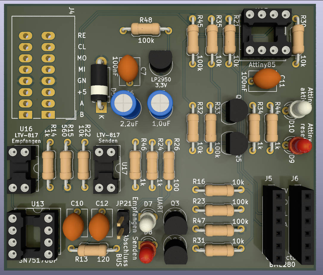
CAD-Ansicht eines Leiterplatten-Layouts
J4 R48 R45 R35 R21 R30 100k 10k 10k RE CL MO MI GN +5 A B K 100nF C7 LP2950 3,3V 100nF C11 Attiny85 Attiny akti D10 R34 R44 R33 R32 10k 10k 1k 1k 1k Q5 D9 R26 R24 R46 100 1k 1k LTV-817 Senden LTV-817 Empfangen U17 R15 560 R14 1k U16 R22 10k U13 C10 C12 JP21 Empfangen Senden Abschluss BUS UART R16
in „BME280 mit Attiny85 auslesen Daten per SN75176 an Pi senden“ · Mikrocontroller und Digitale Elektronik · · Layouts
-
PDF
cdc-2313.pdf
RxD 1 20 GND 2 RESET VCC 19 LED1 3 RXD PB7 18 (RED) 4 TXD PB6 17 R1 5 XTAL2 PB5 16 1 1K5 6 XTAL1 PB4 15 C3 2 7 INT0 PB3 14 104 3 8 PD3 PB2 13 4 9 PD4 PB1 12 R2 PD5 PB0 2 68 10 GND PD6 11 2 CN1 R3 XM7B-0442 68 X1 U1 To MCU 12MHz ATTINY2313 or RS-232C Driver C1 C2 18p 18p Title: AVR-CDC (ATtiny2313) 3 3
in „Soft-USB AVR“ · Mikrocontroller und Digitale Elektronik ·
-
Datei
Temp.asm
clk/4= abt. 1kHz ;*************************************************************************** ; ATtiny26 Pin Assignment: ; 01 PB.0 MOSI/ CW-Tone-out ; 02 PB.1 MISO ; 03 PB.2 SCK ; 04 PB.3 OC1B MotDrive(U) ; 05 Vcc ; 06 Gnd ; 07 PB.4 AD7/RS232negVoltChgPump (T0) ; 08 PB.5 AD8 ; 09 PB.6 AD9/RS232 TxD-
in „Tiny26 Programm ändern in Programm für Mega8“ · Mikrocontroller und Digitale Elektronik ·
-
Datei
TPS_UP.h
; } if (kom == 15 ) // 15: EEProm neu schreiben { if ((dat == 15) && (addr < 3)) { ff++; if (ff == 2) { eeprom_write_byte (&eebyte [0], 0x64); eeprom_write_byte (&eebyte [1], 0x51); eeprom_write_byte (&eebyte [2], 0x4E
in „AVR TTiny 461 Pullup nicht aktiv?“ · Mikrocontroller und Digitale Elektronik ·
-
 Bild
Bild
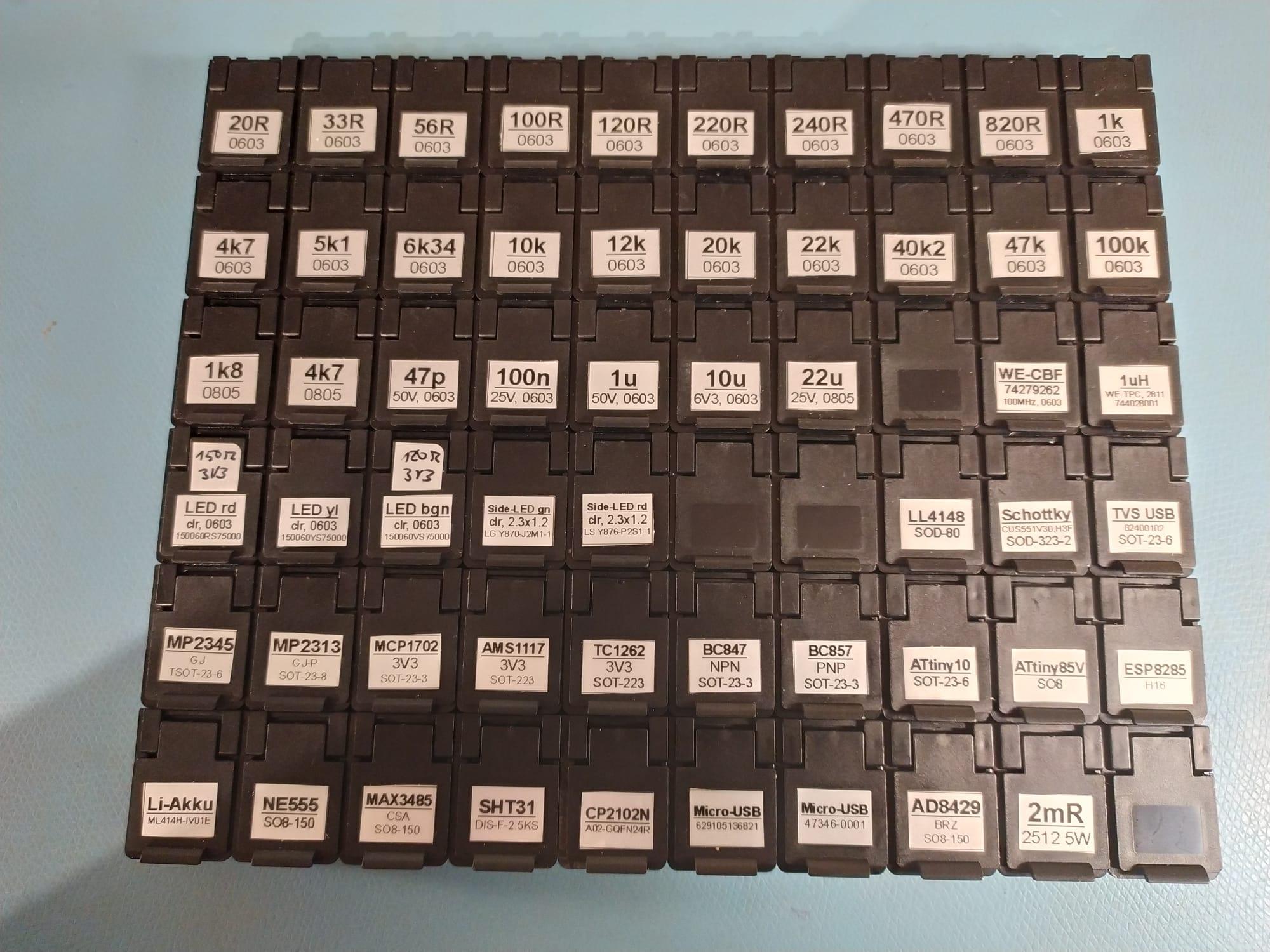
Sortiment an elektronischen Bauteilen in Kunststoffboxen
, 100k 0603, 1k8 0805, 4k7 0805, 47p 25V 0603, 100n 25V 0603, 1u 6V3 0603, 10u 25V 0603, 22u 0805, 15n2 3V2, 12n2 3T2, LED rd, LED vi, LED bgn, side-LED an, side-LED dr, LL4148, Schottky, TVS USB, MP2345, MP2313, MCP1702, AMS1117, TC1262, BC847, BC857, ATtiny10, ATtiny85V, ESP8285, Li-Akku, NE555, MAX3485
in „Dieses Aufbewahrungssystem für SMT Teile“ · Offtopic · · Fotos

-
Datei
Thermometer.asm
;IDE : AVRStudio V4.09 ;µC : ATtiny15L ;Thermometer mit LED-Segmentanzeige .include "tn15def.inc" ; .def Ziffer = r20 ;Dualzahl-Buffer .def ZBuffer = r16 ;Zeichen-Buffer .def LEDAdresse = r17 ;Multiplexer-Adresse .def temp = r18 ;Temporär-Register
in „kleines Problemchen bei ADC-Messung...“ · Mikrocontroller und Digitale Elektronik ·
-
PDF
DE200610__1_.pdf
R1 3 PB2 PB4 6 IN PB3 PB1 1 ATTiny15L OUT2 G10,7MHz MAX1473 L2: OUT 23 4 5mm 7mm 18 DSP 22 R2 IFIN2 DFFB R4 R5 17 IFIN1 DSN 20 C6 1 Ω Ω 9 8 8 MIXIN2 19 220p DFO 4 LNASRC OPP 21 R3 AGND AGND DGND 220k JP1 D1 D2 C7 C8 L2 5 10 13 C9 C10
in „ekg schaltung aus heft 10/2006“ · Analoge Elektronik und Schaltungstechnik ·
-
 Bild
Bild
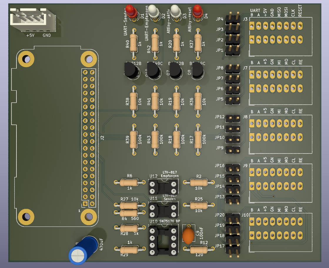
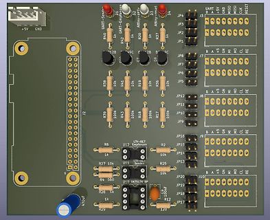
CAD-Ansicht eines Leiterplatten-Layouts
+5V GND UART-Sende D1 UART-Empfang D2 Attiny-aktiv D3 Attiny-reset D4 JP4 JP3 J3 B A +5V GND MOSI CLK RESET R40 1k R42 1k JP2 JP1 R37 1k 12B 49C 2B B 9C JP8 J7 B A +5V GND MOSI CLK RE R38 10k R41 10k R19 10k R36 10k JP5 JP12 JP11 J8 B A +5V GND MOSI CLK RE JP10 JP9 B A +5V GND MOSI CLK RE JP16 JP15 J9 R6 LTV-817 U12 Empfangen R2 10k R27 10k U11 LTV-817 Senden R25 JP14 JP13 R4 560 U10 SN75176 BP JP20 JP19 J10 B A +5V GND MOSI CLK RE R28 1k C9 100nF JP18 JP17 R29 120
in „BME280 mit Attiny85 auslesen Daten per SN75176 an Pi senden“ · Mikrocontroller und Digitale Elektronik · · Layouts
-
Datei
EEPROM_Reading.bas
$regfile = "attiny13.dat" ' ATMEL ATTiny13A @ 9,6 MHz $crystal = 9600000 $hwstack = 26 $swstack = 5 $framesize = 20 Dim Eeprom_adress As Byte Dim Eeprom_byte As Byte Dim Eeprom_array(10) As Eram Byte Config Sda = Portb
in „Panasonic Plasma TV: EEPROM - Modifikation“ · Mikrocontroller und Digitale Elektronik ·
-
Datei
tn85def.inc
" ;* Title : Register/Bit Definitions for the ATtiny85 ;* Date : 2007-02-28 ;* Version : 2.24 ;* Support E-mail : avr@atmel.com ;* Target MCU : ATtiny85 ;* ;* DESCRIPTION ;* When including this file in the assembly program file, all I/O register ;* names
in „Peter Danneggers Bootloader (fastboot) für AVR-GCC-Toolchain“ · Projekte & Code ·
-
Datei
diff-20100825.txt
(1<<LCD_E); LCDD_DDR &= ~ (0x0f << LCD_D4); // Data hold time t_H: min 10ns (10ns) @@ -102,10 +108,15 @@ static inline uint8_t lcd_read4 (void) LCDC_PORT &= ~(1<<LCD_RS); LCDC_PORT |= (1<<LCD_RW); // RW setup time t_AS: min 40ns (60ns) + asm volatile("rjmp 0f\n0:"); // us 20100824 + LCDC_PORT |= (1<<
in „Reziproker Frequenzzähler+ Optimierte 64bit uint Routinen“ · Projekte & Code ·
-
Datei
Synth.asm
db 0,0,0,0,0,0,0,1, .db 1,1,1,2,2,2,2,3, .db 3,4,4,4,5,5,6,7, .db 7,8,8,9,10,10,11,12, .db 12,13,14,15,15,16,17,18, .db 19,20,20,21,22,23,24,25, .db 26,27,28,29,30,31,32,33, .db 34,35,36,37,38,39,40,41, .db 42,43,44,45,46,47,48,49, .db 50,51,52,53,54,55,56,57, .db 58,59,60,61,62,63,64,64, .db 65,66,67,68,69,69,70,71
in „Attiny2313 Timer16 Bit, Normal Mode, unsauber“ · Mikrocontroller und Digitale Elektronik ·
-
Datei
RS232TOLCD1602.c
HD44780 based LCD display Author: DV (April 2014) Hardware: HD44780 compatible LCD text display ATTiny2313 **************************************************************************/ #define F_CPU 9216000UL #define BAUDRATE_INIT 600 // Baudrate nach initialisierung #define BAUDRATE_MAX 57600 // Maximale
in „A tiny project RS232 -> LCD PCB zu verschenken.“ · Mikrocontroller und Digitale Elektronik ·
-
Datei
Attiny25.txt
/******************************************************* Projekt: Aetzwanne Version : ATTiny25 - 1 Erstellt: 20.09.2016 Letze Aenderung: 25.09.2016 Chip: Attiny25 mit internen 8.0 MHz *******************************************************/ /// Header-Dateien/// #include <io.h> #include <delay.h
in „AVR ADC auswerten klappt nicht“ · Mikrocontroller und Digitale Elektronik ·
-
Datei
Synth.asm
.nolist .include "tn2313def.inc" ; Define device ATtiny2313 .list .macro WriteSram ; (register, const) ldi XL, low(SRAM_START) ldi XH, high(SRAM_START) ldi rmp, 0 j0: cpi rmp, @1 breq j1 st X+, @0 inc rmp rjmp j0 j1: ldi XL, low(SRAM_START) ldi XH, high
in „Attiny2313 Timer16 Bit, Normal Mode, unsauber“ · Mikrocontroller und Digitale Elektronik ·
-
Datei
VirtualWire.cpp
defined #endif #include "VirtualWire.h" #include <util/crc16.h> #undef TIMER_VECTOR #ifdef __AVR_ATtiny85__ # define TIMER_VECTOR TIM0_COMPA_vect #elif defined(__AVR_ATtiny84__) || defined(__AVR_ATtiny24__) || defined(__AVR_ATtiny44__) // Why can't Atmel make consistent? # define TIMER_VECTOR TIM1_COMPA_vect
in „Korrigierte "VirtualWire" Library für Attiny84 / 85“ · Projekte & Code ·
-
Datei
irsnd.c
Copyright (c) 2010-2019 Frank Meyer - frank(at)fli4l.de * * Supported AVR mikrocontrollers: * * ATtiny87, ATtiny167 * ATtiny45, ATtiny85 * ATtiny44 ATtiny84 * ATtiny2313 ATtiny4313 * ATmega8, ATmega16, ATmega32 * ATmega162 * ATmega164, ATmega324, ATmega644, ATmega644P, ATmega1284, ATmega1284P * ATmega88
in „IR Fernbedienung mit IRSND“ · Mikrocontroller und Digitale Elektronik ·
-
Datei
RFID-Reader-Modul.c
/* / Projektname : RFID-Reader-Modul / Dateiname : RFID-Reader-Modul.c / Version : 1.0.0 - ATtiny2313 / Datum : 28.12.2013 / Compiler : WinAVR 20100110 libc 1_7_1 / Autor : Johannes Kretzmann / Copyright : johannes.kretzmann@projektsammlung.de / www.projektsammlung.de / / / / Mikrocontroller: ATtiny2313
in „Attiny2313 eeprom Fragen“ · Mikrocontroller und Digitale Elektronik ·
-
Datei
ATtiny85_RDA5807_Radio.c
/************************************************************************** ATtiny85_RDA5807_Radio: UKW Stereo Empfänger mit dem Modul RDA5807M mit OLED I2C Display 64x128 und 3 Tasten zur Steuerung Ressourcen: ATtiny85 @8MHz intern, Fuses Low=E2, High=DF Pinbelegung: PB0=SDA, PB1
in „(sehr) kleines "FrameWork" für ATtiny44“ · Projekte & Code ·
-
Datei
attiny25.c
/******************************************************* Projekt: Aetzwanne Version : ATTiny25 - 1 Erstellt: 20.09.2016 Letze Änderung: 25.09.2016 Chip: Attiny25 mit internen 8.0 MHz *******************************************************/ /// Header-Dateien/// #include <io.h> #include <delay.h
in „AVR ADC auswerten klappt nicht“ · Mikrocontroller und Digitale Elektronik ·
-
Datei
ATTiny861_VGA_asm.bas
'Mini-VGA-Grafikkarte '-------------------- ' 'Mikrocontroller: ATTiny861 'Frequenz: 24,576 MHz 'PORTB.0 = HSync (über 1k Ohm an HSync) 'PORTB.1 = Monochromsignal (über 100 Ohm an R, G & B) 'PORTB.2 = VSync (über 1k Ohm an VSync) 'PORTA = Data 0 - 7 / Adr 0 - 7 'PORTB.3 = Adr 8 'PORTB.6 = WriteClk $regfile = "ATTiny861.dat" $crystal = 24576000 $hwstack = 8 $swstack = 0 $framesize = 8 Config Portb.0 = Output Config Portb.1 = Output Config Portb.2 = Output Config Portb.3 = Input Portb.3 = 1 Config Portb.6 = Input
in „EEPROM-lese-Routine "veräppelt" mich“ · Mikrocontroller und Digitale Elektronik ·
-
Datei
t13schalt4_1.asm
/* RC-Schaltmodul mit 4 Schaltausgängen mit ATTiny13 Es wird der Kanalimpuls einer Modellbau-Funkfernsteuerung ausgewertet. Es können 4 Schaltausgänge geschaltet werden. Für jeden Schaltausgang kann durch bedingte Assemblierung die Betriebsart separat
in „Ich verstehe den Timer0 beim ATtiny 13 nicht.“ · Mikrocontroller und Digitale Elektronik ·
-
Datei
ATTiny861_VGA_asm.bas
'Mini-VGA-Grafikkarte '-------------------- ' 'Mikrocontroller: ATTiny861 'Frequenz: 24,576 MHz 'PORTB.0 = HSync 'PORTB.1 = Monochromsignal 'PORTB.2 = VSync $regfile = "ATTiny861.dat" $crystal = 24576000 $hwstack = 8 $swstack = 0 $framesize = 8 Config Portb.0 = Output
in „VGA-Grafikkarte - Fehler in der Routine zum Schreiben von Daten“ · Mikrocontroller und Digitale Elektronik ·
-
PDF
PCBA_with_elecrow_quotation_BOM.pdf
Layers Dimension Thickness Surface Finished Solder Mask Qty Quotation($) Weight(g) Remark PCBA 2 2.1*15.5 1,2 ENIG (Lead Free Black 50 $62,48 stencil 1 $18,00 Total: $80,48 For PCB Assembly Project Name Pads Qty Price Qty of Boards Quotation Remark SMT 31 0,030 PCBA 50 $62,50 THT 8 0,040 Total: $62,50
in „Erfahrungen mit Platinen von www.elecrow.com“ · Platinen ·
-
Datei
tiny_oled_spi_3wire_b.ino
3wire.ino Demoprogramm zum Anbinden eines SSD1306 OLED-Displays mit nur 3 benoetigten I/O Leitungen des ATtiny-Controllers. Demoprogramm hier fuer ATtiny44/84. Programm sollte durch Abaenderung der Anschlusspins auch auf ATtiny45/85 lauffaehig sein, da die SPI-Schnittstelle nur mittels Bitbanging (und nicht
in „ATtiny85 benötige Taster und kein freier Port“ · Mikrocontroller und Digitale Elektronik ·
-
PDF
resteliste_2.pdf
iCoupler 5,00 € AM28F020A 10 DIL32 256K *8 Flash 3,00 € AQY212SZ 20 SO4 Panasonic Photomos Relais 15,00 € AT45DB081B-TU 10 BGA DATAFLASH SERIAL 20MHZ 8MB 18,00 € AT89C51CC01 15 PLCC44 8051 MCU CAN Controller 25,00 € AT89S8252 15 PLCC44 8-Bit uController 8KB Flash 10,00 € ATTINY2313V-105V 10 SO20 AVR
-
PDF
top2008.pdf
AT90S8515, AT90LS8515, AT90S4434, AT90S8535, AT90LS8535, AT90S4434, AT90LS4434, AT90S2333, AT90S4433, ATTINY11(Hi), ATTINY12(Hi), ATTINY13(Serial), ATTINY15L(Hi), ATTINY25, ATTINY26, ATTINY26L, ATTINY28L, ATTINY28V, ATTINY2313(DIP20), ATTINY2313V(DIP20),ATTINY2313, ATMEGA8, ATMEGA8L, ATMEGA16, ATMEGA16L,
in „[V] Top 853 Universal Programmer + 74er Tester“ · Markt ·
-
Datei
irsnd.c
Copyright (c) 2010-2015 Frank Meyer - frank(at)fli4l.de * * Supported AVR mikrocontrollers: * * ATtiny87, ATtiny167 * ATtiny45, ATtiny85 * ATtiny44 ATtiny84 * ATmega8, ATmega16, ATmega32 * ATmega162 * ATmega164, ATmega324, ATmega644, ATmega644P, ATmega1284, ATmega1284P * ATmega88, ATmega88P, ATmega168
in „IRMP - Infrared Multi Protocol Decoder“ · Projekte & Code ·
-
Datei
irsnd.c
Copyright (c) 2010-2015 Frank Meyer - frank(at)fli4l.de * * Supported AVR mikrocontrollers: * * ATtiny87, ATtiny167 * ATtiny45, ATtiny85 * ATtiny44 ATtiny84 * ATmega8, ATmega16, ATmega32 * ATmega162 * ATmega164, ATmega324, ATmega644, ATmega644P, ATmega1284, ATmega1284P * ATmega88, ATmega88P, ATmega168
in „IRMP - Infrared Multi Protocol Decoder“ · Projekte & Code ·
-
Datei
BT1.asm
------------------------------------------------------- ;*Titel :Steuerung für BT1 ;*Controller :ATTiny12 1,2 MHz intern ;*Sprache :Assembler ;*Autor :bekannt ;*Hardware :für BT1 Layoutversion 1.1 ;* :PB0 an R220->LF357/6, ;* :PB1 an Poti 100k ;* :PB3 an R1k->BC547->R22->CNY17->IRF9640 ;* :PB2 an R1k
in „Assemblerprogramm mit einem Fehler“ · Mikrocontroller und Digitale Elektronik ·
-
Datei
DCF_Filter_Tiny_02.bas
'_Chip = 23 '$regfile = "m16def.dat" '_Chip = 18 '$regfile = "m8def.dat" '_Chip = 17 $regfile = "attiny13a.dat" '$regfile = "attiny13.dat" ' *** Mit Quarz, Frequenz '$crystal = 16000000 '$crystal = 12800000 '$crystal = 7372800 '$crystal = 3686400 ' Tiny13 Original, interner Taktgenerator 9,6MHz und geteilt
in „DCF77 Auswertung (ein bisschen anders)“ · Mikrocontroller und Digitale Elektronik ·
-
Datei
tn461def.inc
" ;* Title : Register/Bit Definitions for the ATtiny461 ;* Date : 2007-02-28 ;* Version : 2.24 ;* Support E-mail : avr@atmel.com ;* Target MCU : ATtiny461 ;* ;* DESCRIPTION ;* When including this file in the assembly program file, all I/O register ;*
in „tn461def.inc : woher, schnell und einfach“ · Mikrocontroller und Digitale Elektronik ·
-
Datei
Zeit.bas
$regfile = "attiny13.dat" 'verwendeter Prozessor $crystal = 1200000 'Definition des Takt $hwstack = 15 'Reservierung im SRAM $swstack = 15 $framesize = 15 Config Portb.0 = Output 'Buzzer Config Pinb.1 = Input Portb.1
in „ATtiny 13 Zeiteinstellung bascom“ · Mikrocontroller und Digitale Elektronik ·
-
Datei
irsnd.c
* * Copyright (c) 2010-2011 Frank Meyer - frank(at)fli4l.de * * Supported mikrocontrollers: * * ATtiny45, ATtiny85 * ATtiny84 * ATmega8, ATmega16, ATmega32 * ATmega162 * ATmega164, ATmega324, ATmega644, ATmega644P, ATmega1284 * ATmega88, ATmega88P, ATmega168, ATmega168P, ATmega328P * * $Id: irsnd.c,
in „IRMP - Infrared Multi Protocol Decoder“ · Projekte & Code ·
-
Datei
Attiny_Motor_Test_2.c
/* * Attiny_Motor_Test_1.c * * Created: 24.09.2014 21:16:27 * Author: Dominik */ #define F_CPU 8000000UL #include <stdlib.h> #include <avr/io.h> #include <avr/interrupt.h> #include <avr/pgmspace.h> #include <util
in „Attiny - Arduino I2C Problem“ · Mikrocontroller und Digitale Elektronik ·
-
Datei
Zeittest.bas
$regfile = "attiny13.dat" 'verwendeter Prozessor $crystal = 1200000 'Definition des Takt $hwstack = 15 'Reservierung im SRAM $swstack = 15 $framesize = 15 Ddrb = &B00000010 'konf Port's B auf > 0=Eingabe 1=Ausgabe Pinb
in „ATtiny 13 Zeiteinstellung bascom“ · Mikrocontroller und Digitale Elektronik ·
-
Datei
fuse.c
programmable attinys * . reset hi-low fuses to factory default on target devices * . layout to drop-on attiny13, attiny25/45/85 8 pin devices targets * . attiny24/44/84 targets needs additional breadboard and jumper wires * . standalone operations, fuses show on 7 segment display * * . project fuse setting
in „Attiny85 neu verfust?“ · Mikrocontroller und Digitale Elektronik ·
-
Datei
fuse.c
programmable attinys * . reset hi-low fuses to factory default on target devices * . layout to drop-on attiny13, attiny25/45/85 8 pin devices targets * . attiny24/44/84 targets needs additional breadboard and jumper wires * . standalone operations, fuses show on 7 segment display * * . project fuse setting
in „Attiny85 neu verfust?“ · Mikrocontroller und Digitale Elektronik ·
-
Datei
Ausschaltverz..bas
$regfile = "attiny13.dat" 'verwendeter Prozessor $crystal = 1200000 'Definition des Takt $hwstack = 15 $swstack = 15 $framesize = 15 Config Timer0 = Timer , Prescale = 1024 'hier wird der timer configuriert Timer0 =
in „Attiny mit Timer und Taster“ · Mikrocontroller und Digitale Elektronik ·
-
Datei
iotn841.h
DAMAGE. ****************************************************************************/ #ifndef _AVR_ATTINY841_H_INCLUDED #define _AVR_ATTINY841_H_INCLUDED #ifndef _AVR_IO_H_ # error "Include <avr/io.h> instead of this file." #endif #ifndef _AVR_IOXXX_H_ # define _AVR_IOXXX_H_ "iotn841.h" #else # error "
in „Neue ATtinies 441 und 841“ · Mikrocontroller und Digitale Elektronik ·
-
Datei
asm-defs.h
easy use of __prologue_saves__ from libgcc. Push the N_PUSHED callee-saved registers Y, R17, R16, R15, ... with 0 <= N_PUSHED <= 18. The frame pointer (Y) is set up according to a frame size of N_FRAME. Clobbers TMP_REG. For the code of __prologue_saves__ from libgcc see http://gcc.gnu.org/viewcvs/gcc
in „ItoA mit Uint64_t“ · Mikrocontroller und Digitale Elektronik ·
-
Datei
tn13Adef.asm
" ;* Title : Register/Bit Definitions for the ATtiny13A ;* Date : 2011-02-09 ;* Version : 2.35 ;* Support E-mail : avr@atmel.com ;* Target MCU : ATtiny13A ;* ;* DESCRIPTION ;* When including this file in the assembly program file, all I/O register ;*
in „Gerät bauen, welches Rauschen produziert (kein Scherz)“ · Analoge Elektronik und Schaltungstechnik ·
-
Datei
definition_tn2313.txt
" ;* Title : Register/Bit Definitions for the ATtiny2313 ;* Date : 2005-01-11 ;* Version : 2.14 ;* Support E-mail : avr@atmel.com ;* Target MCU : ATtiny2313 ;* ;* DESCRIPTION ;* When including this file in the assembly program file, all I/O register
in „Attiny2313 programmieren“ · Mikrocontroller und Digitale Elektronik ·
-
Datei
tn2313def.inc
" ;* Title : Register/Bit Definitions for the ATtiny2313 ;* Date : 2010-08-20 ;* Version : 2.35 ;* Support E-mail : avr@atmel.com ;* Target MCU : ATtiny2313 ;* ;* DESCRIPTION ;* When including this file in the assembly program file, all I/O register
in „Welche .def ist die richtige?“ · Mikrocontroller und Digitale Elektronik ·