-
Datei
irsnd-main-avr.c
additions from m.schoeldgen@hotmail.com * $Id: irsnd-main-avr.c,v 1.3 2016/09/09 08:01:11 fm Exp $ * * ATTINY2313 @ 8 MHz internal RC Osc with BODLEVEL 4.3V: lfuse: 0xE2 hfuse: 0xDC efuse: 0xF9 * * This program is free software; you can redistribute it and/or modify * it under the terms of the GNU General
in „IR Fernbedienung mit IRSND“ · Mikrocontroller und Digitale Elektronik ·
-
Datei
DCF77_Connection.asm
DCF77-Soft-Clock (nach G.Schmidt) ; mit LCD, seriell, 9600 Baud, 8-N-1 ; (RXD/TXD gekreuzt) ; MCU ATTiny4313; ; CPU Takt 4,096 MHz ; LCD 2x16, (HD44780) Vierbitmodus ; PortB LCD Ausgabe: R/W=GND ; PB7 PB6 PB5 PB4 PB3 PB2 PB1 PB0 ; n/a LED ena rs D7 D6 D5 D4 ;- - - - - - - - - - - - - - - - - - - - - - - - - - ;ATtiny4313 memory use summary [bytes]: ;Segment Begin End Code Data Used Size Use% ;[.cseg] 0x000000 0x0001fc 496 12 508 4096 12.4% ;[.dseg] 0x000060 0x000060 0 0 0 256 0.0% ;[.eseg] 0x000000 0x000000 0 0
-
Datei
iotn104.h
DAMAGE. ****************************************************************************/ #ifndef _AVR_ATTINY104_H_INCLUDED #define _AVR_ATTINY104_H_INCLUDED #ifndef _AVR_IO_H_ # error "Include <avr/io.h> instead of this file." #endif #ifndef _AVR_IOXXX_H_ # define _AVR_IOXXX_H_ "iotn104.h" #else # error "
in „Neuer ATtiny104?“ · Mikrocontroller und Digitale Elektronik ·
-
Datei
DCF_ConnSoft.asm
DCF77-Soft-Clock (nach G.Schmidt) ; mit LCD, seriell, 9600 Baud, 8-N-1 ; (RXD/TXD gekreuzt) ; MCU ATTiny4313; ; CPU Takt 4,096 MHz ; LCD 2x16, (HD44780) Vierbitmodus ; PortB LCD Ausgabe: R/W=GND ; PB7 PB6 PB5 PB4 PB3 PB2 PB1 PB0 ; n/a LED ena rs D7 D6 D5 D4 ; Adapter auf LCD-Port: ; PB7 PB6 PB5 PB4 PB3 PB2 PB1 PB0 ; D7 D6 D5 D4 LED n/a ena rs ;- - - - - - - - - - - - - - - - - - - - - - - - - - ;ATtiny4313 memory use summary [bytes]: ;Segment Begin End Code Data Used Size Use% ;[.cseg] 0x000000 0x0001fc 496 12 508 4096 12.4% ;[.dseg] 0x000060 0x000060 0 0 0 256 0.0% ;[.eseg] 0x000000 0x000000 0 0
in „DCF77 Auswertung (ein bisschen anders)“ · Mikrocontroller und Digitale Elektronik ·
-
Datei
intTest.lst
4.1 (C)2018 by DG4FAC ---------------------------------------------------------- Quelldatei: C:\ATtiny85 Lernpaket\Assembler-Files\intTest\intTest.asm Hexdatei: C:\ATtiny85 Lernpaket\Assembler-Files\intTest\intTest.hex Eepromdatei: C:\ATtiny85 Lernpaket\Assembler-Files\intTest\intTest.eep Kompiliert
in „attiny85 interrupt-behandlung“ · Mikrocontroller und Digitale Elektronik ·
-
Datei
EEPROM_Reading.bas
$regfile = "attiny13.dat" ' ATMEL ATTiny13A @ 9,6 MHz $crystal = 9600000 $hwstack = 26 $swstack = 5 $framesize = 20 Dim Eeprom_adress As Byte Dim Eeprom_byte As Byte Dim Eeprom_array(10) As Eram Byte Config Sda = Portb
in „Panasonic Plasma TV: EEPROM - Modifikation“ · Mikrocontroller und Digitale Elektronik ·
-
Datei
releasenotes414rc1.txt
AVR Studio since 4.13 SP2: * ATxmega128A1 * ATxmega64A1 * ATmega32M1 * ATmega32C1 * ATmega32U4 * ATtiny167 * ATtiny88 Check the device matrix in the help system to see which devices are supported by which tools. New Features ============ * Support for the new XMEGA device family in Simulator 2, JTAGICE
in „Honeywell Rondostat HR20E per AVR steuern und konfigurieren“ · Mikrocontroller und Digitale Elektronik ·
-
Datei
Synth.asm
.nolist .include "tn2313def.inc" ; Define device ATtiny2313 .list .macro WriteSram ; (register, const) ldi XL, low(SRAM_START) ldi XH, high(SRAM_START) ldi rmp, 0 j0: cpi rmp, @1 breq j1 st X+, @0 inc rmp rjmp j0 j1: ldi XL, low(SRAM_START) ldi XH, high
in „Attiny2313 Timer16 Bit, Normal Mode, unsauber“ · Mikrocontroller und Digitale Elektronik ·
-
Datei
RGB.asm
lsr r19 ror r18 lsr r19 ror r18 inc r18 sec ror r18 out TCNT0,r18 out SREG,r1 ret CALIBRIEREN: inc r26 cpi r26,1 brne CALIBRIEREN1 ldi r20,14 rjmp BITFERTIG CALIBRIEREN1: cpi r26,10 breq CLIBEND in r20,OSCCAL ; CPU-Takt anpassen sub r20,r25 subi r20,(256-84) out OSCCAL,r20 ldi r20,21 rjmp BITFERTIG CLIBEND
in „PWM und rgb led“ · Mikrocontroller und Digitale Elektronik ·
-
Datei
Einschaltverzoegerung.asm
crystal ;* ;*************************************************************************** .device ATtiny2313 .include "tn2313def.inc" ;ATTiny2313 ;.include "2313def.inc" ;90S2313 .equ Bit0 =0 .equ Bit1 =1 .equ Bit2 =2 .equ Bit3 =3 .equ Bit4 =4 .equ Bit5 =5 .equ Bit6 =6 .equ Bit7 =7 .def temp =R18 .def Delay1 =r23 .def Delay2 =r24 .def Delay3 =r25 .def zeit =r26 .CSEG .ORG 0x00 ;rjmp reset ldi temp,RAMEND ;Initialize stackpointer out SPL,temp ;output Alle auf 11111111 ldi temp,0x00 out portd,temp ldi temp,0xff out DDRD,temp ; Port D ldi zeit,20 rcall Lebe_PortD
in „Attiny 2313 Einschaltverhalten der Ports“ · Mikrocontroller und Digitale Elektronik ·
-
Datei
Strom_25A.bas
23) , 18 Readeeprom Dataregister(24) , 19 Readeeprom Dataregister(25) , 20 Readeeprom Dataregister(26) , 21 Readeeprom Dataregister(27) , 22 Readeeprom Dataregister(28) , 23 Readeeprom Dataregister(29) , 24 Readeeprom Dataregister(30) , 25 Readeeprom Dataregister(31) , 26 Readeeprom Dataregister(32)
in „Fehler in Bascom?“ · Mikrocontroller und Digitale Elektronik ·
-
PDF
IR.pdf
Programm\IR.asm ;************************************************ ;RC 5 decoding programm ;device: ATtiny 13 ;autor: Steven Weyrich ;************************************************ .org 0x0000 ;adress for initial programm rjmp RESET .org 0x0002 ;Adress for pin change interrupt rjmp PCINT0 .org 0x0006
in „Pinchange-Interrupt“ · Mikrocontroller und Digitale Elektronik ·
-
Datei
tn2313def__2_.inc
Y ;* ;* Number :AVR000 ;* File Name :"tn2313def.inc" ;* Title :Register/Bit Definitions for the ATtiny2313 ;* Date :03.06.17 ;* Version :1.00 ;* Support E-mail :avr@atmel.com ;* Target MCU :ATtiny2313 ;* ;* DESCRIPTION ;* When including this file in the assembly program file, all I/O register ;* names
in „Welche .def ist die richtige?“ · Mikrocontroller und Digitale Elektronik ·
-
Datei
tn4313def.inc
" ;* Title : Register/Bit Definitions for the ATtiny4313 ;* Date : 2010-08-20 ;* Version : 2.35 ;* Support E-mail : avr@atmel.com ;* Target MCU : ATtiny4313 ;* ;* DESCRIPTION ;* When including this file in the assembly program file, all I/O register
in „Woher kriege ich die Datei t4313def.inc?“ · Mikrocontroller und Digitale Elektronik ·
-
Datei
tn2313def.inc
" ;* Title : Register/Bit Definitions for the ATtiny2313 ;* Date : 2006-10-03 ;* Version : 2.24 ;* Support E-mail : avr@atmel.com ;* Target MCU : ATtiny2313 ;* ;* DESCRIPTION ;* When including this file in the assembly program file, all I/O register
in „Timer Compare Interrupt Attiny2313“ · Mikrocontroller und Digitale Elektronik ·
-
Datei
LED_blink.asm
; Program LED_blink ; definitions ;.DEVICE ATtiny26 .INCLUDE "tn26def.inc" .DEF var1 = R16 .DEF var2 = R17 .DEF var3 = R18 .DEF var4 = R19 ; Instruction start at adress 0000 .CSEG .ORG 0000 rjmp init ; interupt vectors init: ;set the stackpointer
in „Starthilfe ATtiny26 - läuft nicht an“ · Mikrocontroller und Digitale Elektronik ·
-
PDF
AVR053.pdf
Grouped by oscillator version. Oscillator version Device RC oscillator frequency [MHz] CKDIV PRSCK 1.1 ATtiny12 1.2 1.2 ATtiny15 1.6 2.0 ATmega163 1.0 2.0 ATmega323 1.0 3.0 ATmega8 1.0, 2.0, 4.0, and 8.0 3.0 ATmega16 1.0, 2.0, 4.0, and 8.0 3.0 ATmega32 1.0, 2.0, 4.0, and 8.0 (1) 3.1 ATmega64 1.0, 2.0, 4.0,
in „OSCCAL für 8MHz ?!? be ATTiny26“ · Mikrocontroller und Digitale Elektronik ·
-
PDF
AVR053.PDF
Grouped by oscillator version. Oscillator version Device RC oscillator frequency [MHz] CKDIV PRSCK 1.1 ATtiny12 1.2 1.2 ATtiny15 1.6 2.0 ATmega163 1.0 2.0 ATmega323 1.0 3.0 ATmega8 1.0, 2.0, 4.0, and 8.0 3.0 ATmega16 1.0, 2.0, 4.0, and 8.0 3.0 ATmega32 1.0, 2.0, 4.0, and 8.0 (1) 3.1 ATmega64 1.0, 2.0, 4.0,
in „Osccal für EEPROM bei mega8535 mit Quarz“ · Mikrocontroller und Digitale Elektronik ·
-
Datei
tiny26Wahnsinn.txt
.include "tn26def.inc" .device Attiny26 .org $0000 rjmp Reset .def temp =r16 .def temp2 =r19 ; I/O Pins .equ Frequency_out =1 Reset: ; Stackpointer bis 265 Byte initialisieren ldi temp, RAMEND out SP, temp ;I/O Initialisierung
in „pwm auf tiny26 - hilfääää“ · Mikrocontroller und Digitale Elektronik ·
-
 Bild
Bild
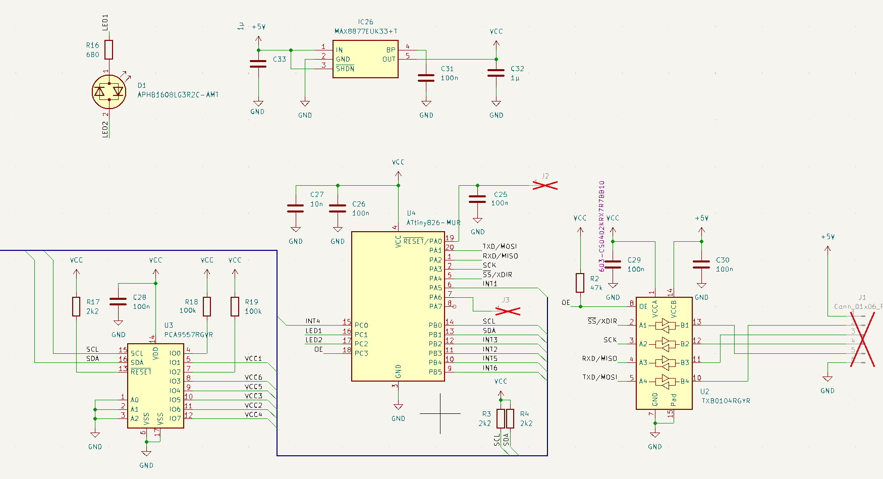
Schaltplan mit ATtiny826 und MAX887
LED1 R16 68Ω D1 APHB1608LG3R2C-AMT LED2 IC26 MAX887EUK43+T C33 100n IN GND SHDN BP OUT C31 100n C32 1µ VCC GND GND U4 ATTiny826-MUR RESET PA0 PA1 PA2 PA3 PA6 INT4 PC0 PC1 PC2 PC3 PB0 PB1 PB2 PB3 PB5 SDA INT3 INT2 INT6 C27 10n C26 100n GND VCC TXD
in „PCA9557 Source Strom per Pin“ · Mikrocontroller und Digitale Elektronik · · Schaltpläne
-
PDF
AVR911.pdf
that use slightly different algorithms are not supported. This applies to the following devices: ATtiny12, ATtiny15, ATtiny26, ATtiny2313, AT90S1200, AT90S2313, AT90S2323/2343, AT90S4433, AT90S8515 and AT90S8535. The bootloader module of AVROSP supports all devices with bootloader capabilities. Note: ATtiny11 and ATtiny28 do not support ISP or bootloader programming, and are not supported by AVROSP. The user could customize the code to support other programmers, e.g. a serial high-voltage programmer.
in „AVR911: Das Ende aller Leiden?“ · Mikrocontroller und Digitale Elektronik ·
-
Datei
dude5.4arduino_avr910.txt
0x1d = (unknown) Device code: 0x1e = (unknown) Device code: 0x1f = (unknown) Device code: 0x20 = ATtiny84 Device code: 0x21 = (unknown) Device code: 0x22 = (unknown) Device code: 0x23 = (unknown) Device code: 0x24 = (unknown) Device code: 0x25 = (unknown) Device code: 0x26 = (unknown) Device code: 0x27
in „avrdude - Probleme unter Mac OS X 10.7 (Lion)“ · Mikrocontroller und Digitale Elektronik ·
-
Datei
dude5.6_avr910.txt
0x1d = (unknown) Device code: 0x1e = (unknown) Device code: 0x1f = (unknown) Device code: 0x20 = ATtiny84 Device code: 0x21 = (unknown) Device code: 0x22 = (unknown) Device code: 0x23 = (unknown) Device code: 0x24 = (unknown) Device code: 0x25 = (unknown) Device code: 0x26 = (unknown) Device code: 0x27
in „avrdude - Probleme unter Mac OS X 10.7 (Lion)“ · Mikrocontroller und Digitale Elektronik ·
-
Datei
dude54arduino.txt
0x1d = (unknown) Device code: 0x1e = (unknown) Device code: 0x1f = (unknown) Device code: 0x20 = ATtiny84 Device code: 0x21 = (unknown) Device code: 0x22 = (unknown) Device code: 0x23 = (unknown) Device code: 0x24 = (unknown) Device code: 0x25 = (unknown) Device code: 0x26 = (unknown) Device code: 0x27
in „avrdude - Probleme unter Mac OS X 10.7 (Lion)“ · Mikrocontroller und Digitale Elektronik ·
-
Datei
ADWandler.txt
sbic ADCSRA, 6 ; warten auf Konvertierung rjmp ADC_MesE in r27,ADCH ; einlesen des High-Teils in r26,ADCL ; einlesen des Low-Teils cp r27,r21 ; Vergleiche Mes-High mit Einzug-High brlo Einschalt ; miss noch einmalwenn zu niedrig cp r26,r20 ; Vergleiche Mes-Low mit Einzug-Low brlo Einschalt ; miss noch
in „AVR Attiny13 Assembler AD Wandler“ · Mikrocontroller und Digitale Elektronik ·
-
Datei
tiny_oled_spi_3wire_b.ino
3wire.ino Demoprogramm zum Anbinden eines SSD1306 OLED-Displays mit nur 3 benoetigten I/O Leitungen des ATtiny-Controllers. Demoprogramm hier fuer ATtiny44/84. Programm sollte durch Abaenderung der Anschlusspins auch auf ATtiny45/85 lauffaehig sein, da die SPI-Schnittstelle nur mittels Bitbanging (und nicht
in „ATtiny85 benötige Taster und kein freier Port“ · Mikrocontroller und Digitale Elektronik ·
-
Datei
dude511.txt
= (unknown) avrdude: Recv: % [25] Device code: 0x25 = (unknown) avrdude: Recv: & [26] Device code: 0x26 = (unknown) avrdude: Recv: ' [27] Device code: 0x27 = (unknown) avrdude: Recv: ( [28] Device code: 0x28 = AT90S4414 avrdude: Recv: ) [29] Device code: 0x29 = (unknown) avrdude: Recv
in „avrdude - Probleme unter Mac OS X 10.7 (Lion)“ · Mikrocontroller und Digitale Elektronik ·
-
Datei
dude511_mit_arduino_conf.txt
= (unknown) avrdude: Recv: % [25] Device code: 0x25 = (unknown) avrdude: Recv: & [26] Device code: 0x26 = (unknown) avrdude: Recv: ' [27] Device code: 0x27 = (unknown) avrdude: Recv: ( [28] Device code: 0x28 = AT90S4414 avrdude: Recv: ) [29] Device code: 0x29 = (unknown) avrdude: Recv
in „avrdude - Probleme unter Mac OS X 10.7 (Lion)“ · Mikrocontroller und Digitale Elektronik ·
-
Datei
dreh.c
: 09.06.2009 Author : Phagsae Company : Comments: Einfache Inkementalgeber Auswerung Chip type : ATtiny26 Clock frequency : 4,000000 MHz *****************************************************/ #include <tiny26.h> #define ERR_OUT PORTB.1 // Wenn hier Aktivität dann ist die Fehlergrenze erreicht. #define
-
Datei
fuse.c
programmable attinys * . reset hi-low fuses to factory default on target devices * . layout to drop-on attiny13, attiny25/45/85 8 pin devices targets * . attiny24/44/84 targets needs additional breadboard and jumper wires * . standalone operations, fuses show on 7 segment display * * . project fuse setting
in „Attiny85 neu verfust?“ · Mikrocontroller und Digitale Elektronik ·
-
Datei
avr910.asm
To program this Device, disable the "Block Mode" by changing "w53: rjmp w6" ;* ;* HISTORY ;* V3.8b 26.02.06 (Klaus) Matched new Devices to avrdude.conf v5.1 ;* V3.8a 30.12.05 (Klaus) Corrected Devic entry for ATTiny13 ;* V3.8 06.11.05 (Klaus) New Devicecodes (inoffiacal) for Mega48/88/168 and others,
-
Datei
avr910.asm
To program this Device, disable the "Block Mode" by changing "w53: rjmp w6" ;* ;* HISTORY ;* V3.8b 26.02.06 (Klaus) Matched new Devices to avrdude.conf v5.1 ;* V3.8a 30.12.05 (Klaus) Corrected Devic entry for ATTiny13 ;* V3.8 06.11.05 (Klaus) New Devicecodes (inoffiacal) for Mega48/88/168 and others,
-
Datei
asm-defs.h
267494&view=markup#l2159 */ #if !defined (__AVR_TINY__) .macro do_prologue_saves n_pushed n_frame=0 ldi r26, lo8(\n_frame) ldi r27, hi8(\n_frame) ldi r30, lo8(gs(.L_prologue_saves.\@)) ldi r31, hi8(gs(.L_prologue_saves.\@)) XJMP __prologue_saves__ + ((18 - (\n_pushed)) * 2) .L_prologue_saves.\@: .endm /* Convenience
in „ItoA mit Uint64_t“ · Mikrocontroller und Digitale Elektronik ·
-
Datei
iotn841.h
DAMAGE. ****************************************************************************/ #ifndef _AVR_ATTINY841_H_INCLUDED #define _AVR_ATTINY841_H_INCLUDED #ifndef _AVR_IO_H_ # error "Include <avr/io.h> instead of this file." #endif #ifndef _AVR_IOXXX_H_ # define _AVR_IOXXX_H_ "iotn841.h" #else # error "
in „Neue ATtinies 441 und 841“ · Mikrocontroller und Digitale Elektronik ·
-
PDF
AVR310_Using_the_USI_module_as_a_I2C_master.pdf
multiple masters on the bus. The Universal Serial Interface (USI) module on devices like ATmega169, ATtiny26 and ATtiny2313 has a dedicated Two-wire mode. The USI provides the basic hardware resources needed for synchronous serial communication. Combined with a minimum of control software, the USI allows
in „ATTiny2313 I2C - Master (Peter Fleury) / Slave (jtronics)“ · Mikrocontroller und Digitale Elektronik ·
-
PDF
Grillen_Fuchs_Beschreibung_V1_0.pdf
Lautsprecher wird ein kleiner Signalgeber genutzt, dessen Spulenwiderstand so hoch ist, dass der ATTINY ihn direkt treiben kann. Wem das Signal zu leise ist, kann dieses jedoch nach Belieben mit einem Transistorverstärker verstärken. Wenn man die Grillen-Funktion nicht benutzen möchte, lässt man den PB1-Pin einfach offen. DerATTINY wird in den Pausen zwischen dem Senden immer in den Power-Down-Modus versetzt. Die Stromaufnahme der gesamten Schaltung beträgt dann etwa 5uA. Wenn im Code das #define PAUSE vergrößert wird, so kann
in „ATTINY 433MHz Fuchssender mit akustischem Grillen-Sound“ · Projekte & Code ·
-
PDF
Grillen_Fuchs_Beschreibung_V1_1.pdf
Lautsprecher wird ein kleiner Signalgeber genutzt, dessen Spulenwiderstand so hoch ist, dass der ATTINY ihn direkt treiben kann. Wem das Signal zu leise ist, kann dieses jedoch nach Belieben mit einem Transistorverstärker verstärken. Wenn man die Grillen-Funktion nicht benutzen möchte, lässt man den PB1-Pin einfach offen. DerATTINY wird in den Pausen zwischen dem Senden immer in den Power-Down-Modus versetzt. Die Stromaufnahme der gesamten Schaltung beträgt dann etwa 5uA. Wenn im Code das #define PAUSE vergrößert wird, so kann
in „ATTINY 433MHz Fuchssender mit akustischem Grillen-Sound“ · Projekte & Code ·
-
PDF
simulavr.pdf
LDI R17, 0x00 R17=0x00 4750 a.out 0x0040: __SREG__,__SP_H__,__do_clear_bss+0x1 LDI R26, 0x60 R26=0x60 X=0x0060 5000 a.out 0x0042: __SREG__,__SP_H__,__do_clear_bss+0x2 LDI R27, 0x00 R27=0x00 X=0x0060 5250 a.out 0x0044: __SREG__,__SP_H__,__do_clear_bss+0x3 RJMP 48 5500 a.out 0x0048: .do_clear_bss_start
-
Datei
test3.c
office@hpinfotech.ro Project : Version : Date : 19.03.2005 Author : Company : Comments: Chip type : ATtiny26L Clock frequency : 1,000000 MHz Memory model : Tiny External SRAM size : 0 Data Stack size : 32 *********************************************/ #include <tiny26.h> // Declare your global variables
in „CodeVision Einsteiger“ · Mikrocontroller und Digitale Elektronik ·
-
Datei
main.c
(Physical) 0x09, 0x30, // USAGE (X) 0x09, 0x31, // USAGE (Y) 0x15, 0x00, // LOGICAL_MINIMUM (0) 0x26, 0xff, 0x00, // LOGICAL_MAXIMUM (255) 0x75, 0x08, // REPORT_SIZE (8bits) 0x95, 0x04, // REPORT_COUNT (2) 0x81, 0x02, // INPUT (Data,Var,Abs) 0xc0, // END_COLLECTION 0x05, 0x09, // USAGE_PAGE (Button)
in „Problem mit libUSB - wie Gerät ansprechen?“ · Softwareentwicklung ·
-
Datei
atmega8burnfuse.c
(datareg),inb(statreg),inb(ctrlreg)); ioperm(datareg, 3, 0); vb_on(); if(argc<3){ printf("usage: TN26px <r|w|f|s|c|z> <filename>\n"); exit(0); } switch(*argv[1]){ case 'R': case 'r': AT_read(argv[2]); break; case 'W': case 'w': AT_prom(argv[2]); break; case 'E': case 'e': AT_EE_read(argv[2]); break;
-
Datei
VirtualWire.cpp
defined #endif #include "VirtualWire.h" #include <util/crc16.h> #undef TIMER_VECTOR #ifdef __AVR_ATtiny85__ # define TIMER_VECTOR TIM0_COMPA_vect #elif defined(__AVR_ATtiny84__) || defined(__AVR_ATtiny24__) || defined(__AVR_ATtiny44__) // Why can't Atmel make consistent? # define TIMER_VECTOR TIM1_COMPA_vect
in „Korrigierte "VirtualWire" Library für Attiny84 / 85“ · Projekte & Code ·
-
Datei
tn461def.inc
" ;* Title : Register/Bit Definitions for the ATtiny461 ;* Date : 2007-02-28 ;* Version : 2.24 ;* Support E-mail : avr@atmel.com ;* Target MCU : ATtiny461 ;* ;* DESCRIPTION ;* When including this file in the assembly program file, all I/O register ;*
in „tn461def.inc : woher, schnell und einfach“ · Mikrocontroller und Digitale Elektronik ·
-
Datei
avrdragon_device_support.html
SCKT3400D1">SCKT3400D1</a></td><td rowspan="1" colspan="1"></td></tr><tr><td rowspan="1" colspan="1">ATtiny12</td><td rowspan="1" colspan="1"></td><td rowspan="1" colspan="1">x</td><td rowspan="1" colspan="1">x</td><td rowspan="1" colspan="1"></td><td rowspan="1" colspan="1"></td><td rowspan="1" colspan=
in „Welches Programmiergerät soll ich mir kaufen?“ · Mikrocontroller und Digitale Elektronik ·
-
PDF
avr450.pdf
closer to the maximum capacity of the battery. Improved ler and the highly integrated low-cost 8-pin ATtiny15 resolution also eliminates the need for external Op-amps to microcontroller, however, it can be implemented using any "window" the voltage. The result is reduced board space AVR microcontroller with
-
Datei
mg.asm
44,43,43,43,42,42,41,40,40,39,39,38,38,37,37,36 .db 35,35,34,34,33,33,32,31,31,30,30,29,29,28,28,27 .db 26,26,25,25,24,24,23,22,22,21,21,20,20,19,19,18 .db 17,17,16,16,15,15,14,13,13,12,12,11,11,10,10,9 .db 8,8,7,7,6,6,5,4,4,3,3,2,2,1,1,0 ;------------------------------------------------------------------
in „Sequencer Prinzip ELM - Wavetable Melody Generator (ASM)“ · Mikrocontroller und Digitale Elektronik ·
-
Datei
Auto-Dimmer01a.BAS
'Auto Licht Dimmer mit ATtiny26L '---------------------------------- ' ' Stand 02.09.2004 00:20 Uhr '---------------------------------------------------------------------------- 'Innenraumleuchen-Dimmer: 'Türkontakt, Lichtschalter
-
Datei
Spannunerfassung_LCD.asm
;Voreinstellungen .device ATtiny26 .nolist .include "tn26def.inc" .list ;Deklarationen .def mp=R16 ;allgemeine Register .def adhigh=R17 ;Ergebnis vom ADC ;Stackpointer initialisiern ldi mp, RAMEND out SP, mp ;Definition der Ein und
in „Attiny26_Spannungerfassung“ · Mikrocontroller und Digitale Elektronik ·
-
Datei
Display.asm
.device ATtiny26 .include "tn26def.inc" ;Deklarationen .def mp=R16 .def mp1=R17 .def mp2=R18 .def mp3=R19 ;Stackpointer initialisieren ldi mp, RAMEND out SP, mp ;Ein- und Ausgänge definieren ldi mp, 0b11111111 out
in „Verzweifelt keine Anzeige am LCD“ · Mikrocontroller und Digitale Elektronik ·
-
Datei
Spannunerfassung_LCD1.asm
***************************************************************; ;Grundinitialisierungen .device ATtiny26 .nolist .include "tn26def.inc" .list ;Deklarationen .def mp=R16 ;allgemeine Register .def adhigh=R17 ;Ergebnis vom ADC .def mp1=R18 .def mp2=R19 .def mp3=R20 ;Stackpointer initialisiern ldi mp, RAMEND
in „Verzweifelt keine Anzeige am LCD“ · Mikrocontroller und Digitale Elektronik ·