Times Profile Feature Lead-Based Solder Lead-Free Solder Average Ramp-Up Rate (Ts maxto Tp ) 3℃/second max. 3℃/second max. Preheat: Temperature Min (Ts ) 100℃ 150℃ min Preheat: Temperature Min (Ts ) 150℃ 200℃ max Preheat: Time ( min tomax) 60-120 seconds 60-180 seconds Time Maintained Above: Temperature
Max I. schrieb im Beitrag #7554202: > Genau deswegen macht man sowas nicht. a) da ist extrem wahrscheinlich nix wichtiges drauf b) die 1-8MB muss man unter 6TB auch erstmal finden. c) mit dd in der
Max I. schrieb im Beitrag #7554227: > ..viel Prosa um zu beschreiben, warum "dd if=/dev/zero of=/dev/sdx" im > Terminal angeblich zu schwer für die Welt ist. Oh weia. Mir nicht. - Linux suchen.
.................................................................................................. 134 7.9.1 Sub Clock ............................................................................................................................. 134 7.9.2 Power Control....................................................................................................................... 134 8. Bus 135 8.1 Bus Setting .................................................................................................................................. 135 8.2 Peripheral Bus Timing Setting ..
different recommendations for stencil design. www.ti.com PACKAGE OUTLINE DBV0005A SOT-23 - 1.45 mm max height SCALE 4.000 SMALL OUTLINE TRANSISTOR C 3.0 2.6 0.1 C 1.75 B 1.45 A 1.45 MAX PIN 1 INDEX AREA 1 5 2X 0.95 3.05 2.75 1.9 2 1.9 4 3 0.5 5X 0.3 (1.1) 0.15TYP 0.2 C A B 0.00 0.25 GAGE PLANE 0.22TYP
Transceiver-Typ IP65 bis 70 °C 12000 min -1, 10000 min (Dauerbetrieb) -1 -1 Zulässige Last / Kanal max. +/- 20 mA IP65 bis T max 8000 min , -100 min (Da-1rbetrieb) Signalpegel HIGH typ. 3,8 V IP67 bis 70 °C 11000 min , 9000 min (Dauerbetrieb) IP67 bis T max 8000 min , 5000 min (Dauerbetrieb) LOW bei
Beispiel des CFM Leap 1A/1C beträgt der Verbrauch 14.4 g/kN/s. Das Ding macht einen Startschub von 137kn, max. continuous sind 133kn drin. Heißt, wenn man das Ding eine Stunde lang mit max. continuous thrust laufen lässt, gehen dafür knapp 6.900kg Treibstoff drauf. Auf Reiseflughöhe schafft das Ding das aber
-800 mehr als denen der MAX), das ist gemessen an der Treibstoffkapazität (20,7 Tonnen bei der B737 MAX in der Basisversion) relativ wenig. Heißt von vollgetankt bis furztrocken (natürlich nicht erlaubt, für weniger als 30 Minuten
20 I = DC Current (A) L = EffectivePath Length (cm) OD (nom. - bare core) 33.02 mm 1.300 in 10 e (max. - after coating) 33.53 mm 1.320 in 0 (nom. - bare core) 19.81 mm 0.780 in 1 10 100 1,000 ID (min. - after coating) 19.30 mm 0.760 in H - DC MagnetizingForce (Oe) Ht (nom. - bare core) 11.10 mm 0.437 in (max. - after coating) 11.73 mm 0.462 in 106 %InitialPerm vs. Peak AC FluxDensity - Mix-06 (8.5µ) Mass (approximate) 29 grams s 105 o A e Eff. Mag. Cross Section 0.698 cm² i n Le- Eff. Mag. Path Length 8.28
20 I = DC Current (A) L = EffectivePath Length (cm) OD (nom. - bare core) 33.02 mm 1.300 in 10 e (max. - after coating) 33.53 mm 1.320 in 0 (nom. - bare core) 19.81 mm 0.780 in 1 10 100 1,000 ID (min. - after coating) 19.30 mm 0.760 in H - DC MagnetizingForce (Oe) Ht (nom. - bare core) 11.10 mm 0.437 in (max. - after coating) 11.73 mm 0.462 in 106 %InitialPerm vs. Peak AC FluxDensity - Mix-06 (8.5µ) Mass (approximate) 29 grams s 105 o A e Eff. Mag. Cross Section 0.698 cm² i n Le- Eff. Mag. Path Length 8.28
Therefore, as shown in Fig. 7.14, the B6-bridge and CHB inverter’s voltage ripples are at D = 0.5 and V DC,max /2 and V batt,max2, respectively. The maximal peak current ripple on the inductor ∆I is set at 5% of the peak current. L,max Considering the battery maximal current of I batt,max= 36A, the current ripple
different recommendations for stencil design. www.ti.com PACKAGE OUTLINE DBV0005A SOT-23 - 1.45 mm max height SCALE 4.000 SMALL OUTLINE TRANSISTOR C 3.0 2.6 0.1 C 1.75 B 1.45 A 1.45 MAX PIN 1 INDEX AREA 1 5 2X 0.95 3.05 2.75 1.9 2 1.9 4 3 0.5 5X 0.3 (1.1) 0.15TYP 0.2 C A B 0.00 0.25 GAGE PLANE 0.22TYP
Dimension Drawing (9mm*9mm) D (9mm) GeneralSize D1 (7mm) Measuring unit: mm/mm 36 25 SYMBOL MIN TYP MAX A - - 1.60 A1 0.05 - 0.15 A2 1.35 1.40 1.45 37 24 A3 0.59 0.64 0.69 b 0.18 - 0.27 b1 0.17 0.20 0.23 c 0.13 - 0.18 ) c1 0.12 0.127 0.134 ) m D 8.80 9.00 9.20 m m ( ( D1 6.90 7.00 7.10 E E E 8.80 9.00
service. 132,131, 130,129, 128 DREQ[7:5], 58, 52, I DMA Request - Channels [7:5], [3:0] DREQ[3:0] 46,134, DREQ inputs are asserted by ISA DMA devices to request a DMA transfer. The 7,137,42 request must remain asserted until the corresponding DACK# is asserted. DACK[7:5]#, 57,51, O DMA Acknowledge- Channels
Werden die zusätzlich zu den zu speichernden Spannungs- und Strom-Werten auch die Begrenzungen (also Max-Spannungs- und Max-Strom-Werte) mit gespeichert und wieder abgerufen wenn man den entsprechenden Speicher aufruft?
bit multiplikation. Timing: Es wird timinganalyze gemacht, für LED blinky (26 bit counter) ist max Frequenz als 188 MHz angegeben. Wegen der fehler in VHDL ist es aber auch mit 250MHz gelaufen (naja an 9 platinen von 10). LED blinky benutzt 34 CPE's. Das 18x6 MULT nimmt 115 CPE's und hat max Clock 134MHz. Natürlich ist LED blink nicht massgebendes demo, da wollte ich den InstantSoC RISC-V ausprobieren. Leider ist der Yosys nicht fähig den InstantSoC SystemVerilog zu synthesieren, es scheitert
-------------------------------- # Id Hash-Function Insert/Search-Cycles Coll-Rate Max-Coll Total-Coll Used-RAM # ------------------------------------------------------------------------------------------------ 1 Paul Larson 57 77 1.79
table_size; /* Table size */ UINT64 used_entries; /* Used entries */ UINT64 max_dib; /* Max DIB (Distance to Initial Bucket) */ UINT64 collisions; /* Sum of the DIB of all entries */ } HT_STAT; BOOL HT_GetStat(HASH_TABLE *ht, HT_STAT *sp, HT_HASH
URC line device, is determined by the following formula: R I M H logJF hh hh 2 π L J h hhhh J J Q max L L L K O P N = hhhhhhhhhhhhhhhhhhhhhhhhhhhhhh log K The URC line is made up strictly of resistor and capacitor segments unless the ISPERL parameter is given a non-zero value, in which case the capacitors
generated when the counter is equal to TOP. If TOP is updated to a value lower than count upon reaching MAX, the counter restarts from BOTTOM. Figure 21-3. Periodic Interrupt Mode MAX and Event) Request TOP CNT BOTTOM TOP changed to CNT set to BOTTOM a value lower than CNT 21.3.3.1.2 Time-Out Check Mode In
] x 0.100” [2.54mm] L. Element Pitch: 0.020” [0.51mm]. Luminance: 70 foot lamberts. [147.32] 5.30 [134.62] 3.95 STANDARD ELECTRICAL SPECIFICATIONS [100.33] DESCRIPTION MIN. TYP. MAX. UNITS Panel Supply Voltage + 11.4 + 12.0 + 12.6 V [17.27] .135 Panel Supply Current - - 0.75 A .790 [3.429] .030±.020
standards. for 3 through 20 amp models. • Replaces slow blow glass cartridge fuse. Reset Time: 180 seconds max. for 0.25 through 2 amp models. 5 to 30 seconds for 3 through 20 amp models. • Labor-saving snap-in mounting. • Button extends for visual trip indication. Agency Approvals W28 series is UL 1077 Recognized
Signal zu einem Empfänger weiterleitet. Sagen wir mal ein RTL-SDR. In den Specs des Verstärkers steht: max 250mW. Was kommt denn dann bei mir am anderen Kabelende an "Leistung" an? Und was brauche ich für einen Dämpfungsglied, damit mir der Verstärker die Eingangsstufe nicht zerstört?
Frank H. schrieb im Beitrag #7498485: > Interessant ist das Signal an 134.2 kHz. Also der Deutsche Wetterdienst DCF54. Sendet der überhaupt noch? Nach meinen Unterlagen ein 50kW Sender, der ebenso wie der 50kW Zeitzeichensender DCF77 in Mainflingen steht. Wegen der
Danke, leider zu breit.. 8 oder max. wirklich 16 Zeichen, 10 Zeichen würden auch schon reichen
Daniel E. schrieb im Beitrag #7496818: > Danke, leider zu breit.. Gib die max. Breite doch einfach mal an, für die Platine bzw. das eigentliche Display. Vorher lohnt es nicht zu suchen.
DELAY Switch Off Delay Time 300 ns Internal Time Control Section T OFF_MIN Minimum OFF Time 3 us T OFF_MAX Maximum OFF Time 340 us T ON_MAX Maximum On Time 53 us MOSFET Section Static Drain-source RDSON Vcc=7V/Id=0.5A 12.8 16 ohm On-resistance Drain-Source Breakdown V DS_BD Vgs=0V/Id=250uA 500 V Voltage
Ich habe 3 BTS in gebrauch. Zum vergleich muss ich nur die Platine umstecken. Ohne Last habe ich max. 1 ADC Digitalwert vom ADC, mit dem Problem-BTS sendet der NANO ADC 250. Ich würde da auch nicht so viel nachfragen, aber ich habe von 3 Anwendern ein soches Problem berichtet bekommen. Daher will
Lokdecoder arbeite. Bemerkung: Der ADC Wert steig bei 153 mA um ca. 3 . Da wäre dann (153mA - 19mA = 134mA) Div 3 = 44 mA Bei 4 Ampere theoretisch 4000 / 44 = 90 als ADC Wert + den Offset Ich könnte wahrscheinlich den 1 K z. B durch 2K ersetzen. Dann ist aber der Offset 253 noch höher ? ?? aber
PARAMETER SYMBOL UNIT MIN MAX (1) VCC (min) to /CS Low tVSL 20 µs (1) Time Delay Before Write Instruction tPUW 5 ms (1) Write Inhibit Threshold Voltage V WI 1.0 2.0 V Note: 1. These parameters are characterized only. VCC VCC (max
VD-01 VD-02 VD-03 VD-04 Max.cooling area 80litres 30 litres 170 litres 130 litres contentat 35 mm PU insulation: Max.cooling area 100 litres 50 litres 200litres 170 litres contentat 50 mm PU insulation: Power consumption: 35W
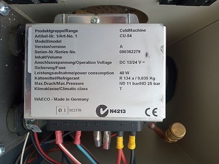
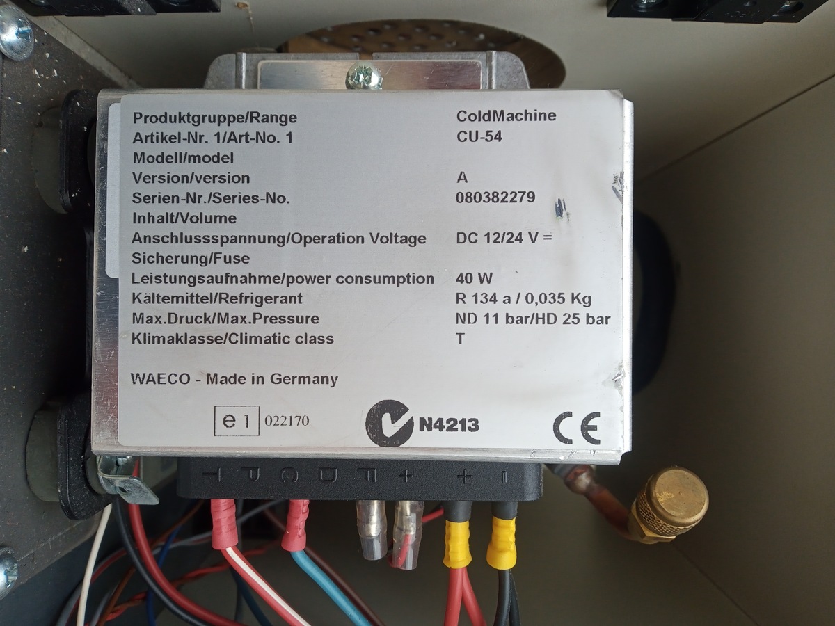
Voltage DC 12/24 V =
Sicherung/Fuse
Leistungsaufnahme/power consumption 40 W
Kältemittel/Refrigerant R 134 a / 0,035 Kg
Max.Druck/Max.Pressure ND 11 bar/HD 25 bar
Klimaklasse/Climatic class T
WAECO - Made in Germany
e1 022170
N4213
CE
einer Kenterung hätte ich eher Angst, dass es irgendwo auf Grund liegt. Wasserdicht müsste es bis max. 1m sein. Da mache ich mir eigentlich aber weniger Sorgen. Solar braucht es nicht, es würde ein kleiner Akku reichen, der so ca. 6h durchhält. ODer bauen die dann schon zu groß? Wenn es ein Kompassmodul
man mit eine Updaterate so in der Gegen von 0.5 bis 1s leben kann. > Wasserdicht müsste es bis max. 1m sein. Da mache ich mir > eigentlich aber weniger Sorgen. Das zeigt eigentlich nur wie wenig Ahnung du hast. :-) Du hast immer Luftfeuchtigkeit die alleine schon kritisch ist. Und wenn das
Philips. Note *2: For maximum ambient temperature T A(ma, please refer to “ORDERING INFORMATION” on page 134. 3 MB91460D Series ■ PRODUCT LINEUP MB91F467DA Feature MB91V460A MB91F465DA MB91F467DB Max. core frequency (CLKB) 80MHz 100MHz 96MHz Max. resource frequency (CLKP) 40MHz 50MHz 48MHz Max. external bus
coordinates exceed the maximum pattern size, the repeat, cramp or border color option is selected. S (max. ±8192) ) 9 8 max. 4096 pixels . a ( T Origin e p Texture 6 pattern 0 x a m 8.1.3 Frame buffer For drawing, the following area must be assigned to the Graphics Memory. The frame size (count of pixels
UMICH (J H-H 4) REA RVIEW R 4 1 3 1 E X T E R N A L V I EW R 4131E X T171 1-A ) 0 0 LCL RMT —WRITE 0 - MAX STORE ~VIEW RECALL SAVE —SHIFT INPUT ATTENUATOR - — SWEEP VIDEO I0kHz- .5GHz ( r n i r l R4131A SPECTRUM ANALYZER FREERUN 0 TDE/DIV FLTR +20dBMAX S T A R T H 25VDC MAX P E R /RESET LINE OFF ON PHONE
4.2, VDD = 1.8V, VDDIO = 1.8V, T =25°C, unless otAerwise noted. PARAMETERS CONDITIONS MIN TYPICAL MAX UNITS NOTES I C TIMING I C FAST-MODE fSCLSCL Clock Frequency 400 kHz 1, 2 tHD.STA, (Repeated) START Condition Hold 0.6 µs 1, 2 Time tLOW , SCL Low Period 1.3 µs 1, 2 tHIGH, SCL High Period 0.6 µs 1,
name Pin I/O Description DC features Note number USIM_DATA 15 IO USIM card data 1.8V USIM: - bus V max=0.6V IL V IHn=1.2V V OLx=0.45V V min=1.35V OH 3.0V USIM: V max=1.0V IL V IHn=1.95V V OLx=0.45V V min=2.55V OH USIM_CLK 16 DO USIM card clock 1.8V USIM: - line V OLmax=0.45V V min=1.35V OH 3.0V USIM:
Storage temperature Min. -65⁰C Max. +160⁰C Soldering IEC 68-2-20 Wave – max 260⁰C for max. 10 sec., please refer to usage guidelines Soldering iron – max. 350⁰C for max. 3 sec. Flux tight. Environmental Endurance IEC 68-2-3 Temperature
Max schrieb im Beitrag #7432479: > Ist der einzige unterschied zwischen SA828-V und SA828-U die > vorprogramierten Frequenzen oder gibt es tatsächlich einen Hardware > Unteschied? Nachdem das Datenblatt
the maximum pulse power dissipation is limited either by the maximum temperature difference Tj-mb max (Eq. 2), or by the maximum junction temperature T jmax and so by analogy with Eqs. 3 and 4: Tj −mb max P tot maxK , 7 Zthj −mb when T mb ≤ Tmb K and: Fig. 10 Three limit cases of rectangular pulse loads
Stellungen: ±3% Ein wesentliches Qualitätsmerkmal dieses Oszilloskops ist vor allem die variabel 2.5:1 bis max. 0,5s/cm hohe Übertragungsgüte der Meßverstärker mit max. 1% Überschwingen. mit X-Mag. x10 ±5%; 10ns/cm: ±8% Damit diese –von der Tastspitze bis zumBildschirm–ständig kontrollierbar ist, Holdoff: variabel
Semiconductors Product specification NPN general purpose transistor BC337 FEATURES PINNING • High current (max. 500 mA) PIN DESCRIPTION • Low voltage (max. 45 V). 1 emitter 2 base APPLICATIONS 3 collector • General purpose switching and amplification, e.g. driver and output stages of audio amplifiers. handbook
.................................... 3. Revise Max t , t RromF15ns to 40ns in Table 11 - 8080-Series MPU Parallel Interface Timing Characteristics .......................................................................................................................................... 4. Revise Max t , t RromF15ns to 40ns in Table 12 – Serial Interface Timing Characteristics.....................d Table 1 - Ordering Information....................................................................
: 0] Operating mode TOP value Update OCR0X moments Set TOV0 at all times 0 Normal 0xFF immediately MAX 1 PCPWM 0xFF TOP BOTTOM 2 CTC OCR0A immediately MAX 3 FPWM 0xFF TOP MAX 4 Keep it - - - 5 PCPWM OCR0A TOP BOTTOM 6 Keep it - - - 7 FPWM OCR0A TOP TOP The following table shows the polarity control of
Part Number Marking V I @V V @I I V @I I ① R R R BR T T C PP PP Uni-Polar Bi-Polar Uni Bi V μA min(V) max(V) mA max(V) A SMCJ5.0A SMCJ5.0CA GDE BDE 5.0 300 6.40 7.00 10 9.2 163.0 SMCJ6.0A SMCJ6.0CA GDG BDG 6.0 250 6.67 7.37 10 10.3 145.6 SMCJ6.5A SMCJ6.5CA GDK BDK 6.5 150 7.22 7.98 10 11.2 134.0 SMCJ7.0A

 Bild
Bild