-
PDF
Class_1_Bluetooth_Module_with_EDR_Support_DS500022-2257897.pdf
Product Development, Quicker Time to Market • Compatible with Microchip Microcontroller Fami- lies (PIC16F, PIC18F, PIC24F/H, dsPIC33 and PIC32) • Up to 100 meter range 2021 Microchip Technology Inc. DS50002280B-page 1 RN41/RN41N RN41/RN41 MODULE VARIANTS (1) Model Antenna Firmware Description RN41
in „[V] Microchip Bluetooth Module RN41-I/RM und RN42-I/RM“ · Markt ·
-
PDF
Druck.pdf
Benutzerliste | Bildergalerie | Hilfe | Login ATmega48, 1090MHz, USB-ISP Brenner , SOS.--- Autor: J. Joyce (forrestjump) Datum: 03.02.2010 23:26 Angehängte Dateien: homebrewADSB.jpg 99,8 KB, 192 Downloads guten abend, beiße mir gerade an folgendem Projekt die Zähne aus, weil Novize .... http://www.lll.lu
in „Bug? beim Internetausdrucken“ · www.mikrocontroller.net ·
-
PDF
STM_DEV.pdf
PIU2501VDDTX VSSTX PI223018 PISB30L1A YELLOU CK15 CK16 PIU2802VDDOSC VSSOSC PI2C3022 RK2323 L2A 0 P010pF P010pF PIUC302VDD VSS P I U C 3 0 2 PIRK2PIRK23PISB30L2A RIGHT SchirmISB300 ENC28J60 SOIC28 100R PISB30L2B GREEN SchirmISB300 C GND GND SS12 GND C PISS1101 SB3B VCC PISS1202 GND Stiftleiste 2pol VCC
in „STM32 Development Board“ · Mikrocontroller und Digitale Elektronik ·
-
PDF
EjN-ST-A10_LIUST-5X_CustomerDisplay.pdf
light up the triangle mark as shown below (P4P3P2P1P0). P4 P3 P2 P1 P0 0000 1111 0111 0011 0001 b 0 F 7 3 1 h *1 Liu_outs(“\x1b\\?LT0F731”); LIUST-51 A B C D E F G H I J K L M N O P Q R S T *1 See Appendix-A3. 11) Identification Code Format: ESC[c or ESC[0c (1B 5B 63 or 1B 5B 30 63) Function: Reads the
in „Hat schon jemand was mit dem FUJITSU VF60 Display gemacht?“ · Mikrocontroller und Digitale Elektronik ·
-
PDF
TC2014.pdf
26: Output Noise vs. Frequency. (C OUT = 10 µF Tantalum). DS21662F-page 8 2001-2012 Microchip Technology Inc. TC2014/2015/2185 3.0 PIN DESCRIPTIONS 3.3 Shutdown Control Input (SHDN) The descriptions of
in „Mcp3551 PT1000 Schaltung“ · Mikrocontroller und Digitale Elektronik ·
-
PDF
MSP-EXP430G2_LaunchPad.pdf
R10 1 10k 0402 19 R11 1 15k 0402 20 U1 1 MSP430F1612IPMR 21 U4 1 TPD2E001DRLR 22 U3 1 TUSB3410VF 23 U2 1 TPS77301DGKR 24 U5 1 I2C EEPROM 128k (AT24C128-10TU-2.7) 25 TP1, TP2, TP3, TP4, TP5, TP6, TP7 26 C14 1 1nF, SMD 0603
in „gutes Übersetzungsprogramm für Datenblätter gesucht“ · Offtopic ·
-
PDF
39662c.pdf
VSSOSC Byte-Wide Random and Sequential Access with SCK J Auto-Increment 8 0 21 VSSPLL CS 9 20 VDDPLL Internal DMA for Fast Data Movement RESET 10 19 VDDRX VSSRX 11 18 VSSTX Hardware Assisted Checksum Calculation for TPIN- 17 Various Network Protocols 12 TPOUT
in „Webserver mit XC167“ · Mikrocontroller und Digitale Elektronik ·
-
Datei
Descriptions.txt
Widerstand 20 SMD SHUNT RESISTOR 20 Silicon Schottky Diodes 20 N-CHANNEL MOS FET 20 Low Signal Relay 18 MKDSN 1,5/ 2-5,08 Printklemme 18 CRYSTAL RESONATOR 17 SOLDER PAD E1553, drill 1,4mm, distributor Buerklin, 07F820 16 SMD solder JUMPER 16 Kingbright 14.2mm (0.56 INCH) SINGLE DIGIT NUMERIC DUISPLAY 16
in „[KiCad] Bibliotheksaufbau - Konzeptideen gesucht“ · Platinen ·
-
PDF
50002370A.pdf
output. Connect to 1 µF low ESR ceramic capacitor. 11 9 P04 DO Status Indicator 2 (STATUS_IND_2). See Section 1.5 “Status Indication I/O Pins”. 12 10 P15 DO Status Indicator 1 (STATUS_IND_1). See Section 1.5 “Status Indication
in „[V] 2St. Microchip Bluetooth4.0 Module RN4677“ · Markt ·
-
PDF
14_hoofdstuk14.pdf
Connector Gemeen- Dochterbordje dochterbordje schappelijk nummering nummering FPGA I/O Signaal singaal J1A 1 GND J1B 2 13 VGA_VS J1C 3 17 RS J1D 4 22 E J1E 5 28 S/Pdif J1F 6 30 OSC J1G 7 40 IR J1H 8 43 CSB J1I 9 45 A0 J1J 10 46 A1 J1K 11 48 Audio R J1L 12 54 AudioL J1M 13 56 Data in J1N 14 58 Data out J1O 15 3V3 J2A 16 11 VGA_HS J2B 17 15 VGA_R J2C 18 21 VGA_G J2D 19 27 VGA_B J2E 20 29 PS/2 CLK J2F 21 37 PS2/ DATA J2G 22 38 RS_232_TXD J2H 23 39 LED7 AUD_BCLK J2I 24 44 LED6 AUD_DACDAT J2J 25 47 LED5 AUD_DACLRC
-
PDF
PIC16F1503.pdf
o e E a r F 1 C i D P T PIC12(L)F1501 (1) 1024 64 6 4 1 1 2/1 4 — — 1 2 1 — — PIC16(L)F1503 (2) 2048 128 12 8 2 1 2/1 4 — 1 1 2 1 — — PIC16(L)F1507 (3) 2048 128 18 12 — — 2/1 4 — — 1 2 1 — — PIC16(L)F1508 (4) 4096
in „Versorgungsspannung vom PIC mit PIC messen“ · Mikrocontroller und Digitale Elektronik ·
-
PDF
CAN___C_Dez2010_Bestueckung.pdf
SW_A_C2 SW_A_P2 K1X01 K1X01 C22 100n R8 CanµC1 v1 1K R26 10K T2 NDS355N 10Dez2010 R9 10K F1 C13 10µ R1 C10 D3 0A25FF C14 1R 100n 10µ 3 R BAV70 C15 C4 I U R2 10µ T 1R C D2 D6 10µ 0 T1 NDS355N 1 X C3 J R18 A 10µ M IC4 R14 M S SS14 10K 1K D4 T4 NDS355N LED-SMD1206
in „Konzept zu einem Hausbus auf CAN-Bus Basis und die Enstehung des Konzeptes“ · Haus & Smart Home ·
-
PDF
CAN_uc_Dez2010_Bestueckucg.pdf
SW_A_C2 SW_A_P2 K1X01 K1X01 C22 100n R8 CanµC1 v1 1K R26 10K T2 NDS355N 10Dez2010 R9 10K F1 C13 10µ R1 C10 D3 0A25FF C14 1R 100n 10µ 3 R BAV70 C15 C4 I U R2 10µ T 1R C D2 D6 10µ 0 T1 NDS355N 1 X C3 J R18 A 10µ M IC4 R14 M S SS14 10K 1K D4 T4 NDS355N LED-SMD1206
in „Anforderungssammlung CAN Hausbus mit PIC µC“ · Haus & Smart Home ·
-
PDF
MCP6562.pdf
e e A A2 c A1 L 3,KNYR5445R)J)XV PK&\,YKH,04K&KNY R55 56R RW7 53&8\70H801K,Y5 2 1KNSQ \ FD920;VE 6±\7[''0:\K6QN W FD;F < %D%F RH'Z\Z01[S [6\0JQKS ,\YY WL FD;F < %DFF VN[,ZH88 W% FDFF < FD%F 6±\7[''0=KZNQ ) %D;F LD%F LDGF RH'Z\Z01
in „Schmitttrigger mit MCP6562 unklare Abweichung“ · Analoge Elektronik und Schaltungstechnik ·
-
PDF
mcp23009.pdf
Technology Inc. DS22121B-page 1 MCP23009/MCP23S09 Package Types: MCP23009 PDIP/SOIC QFN P P P P VDD 1 18 V SS 7 6 5 4 N/C 2 17 NC 6 5 4 3 SCL 3 16 NC VSS 1 12 GP3 SDA 4 15 GP7 NC 2 11 GP2 17 ADDR 5 14 GP6 VDD 3 10 GP1 RESET 6 13 GP5 SCL 4 9 GP0 INT 7 12 GP4 5 6 7 8 GP0 8 11 GP3 A R T GP1 9 10 GP2 S D S
in „Frage zu SPI und MCP23S09“ · Mikrocontroller und Digitale Elektronik ·
-
Datei
rfm70.cpp
pitfalls, todo, known problems, etc //! //! - pictures for power //! - document (other) files //! - PIC18F examples, Cortex C examples, Arduino //! - write 5 bytes when address <5 bytes? //! - check and improve rtf documentation //! - check CE cycling requirements //! - descriptions for the other files
in „RFM70 Arduino Probleme“ · Mikrocontroller und Digitale Elektronik ·
-
Datei
Testplatine.c
/* Testplatinenprogramm geschrieben von Mike Riedel Januar 2014 // Pinbelegung PIC 18F2420 RB7 RB6 RB5 RB4 RB3 RB2 RB1 RB0 VDD VSS RC7 RC6 RC5 RC4 | + ### ### ### ### ### ### ### ### ### ### ### ### ### ### + | | 28 27 26 25 24 23 22 21 20 19 18 17 16 15 | | +-+ | | | | | +-+ | |
in „Fehlerhafte Werte bei AD-Wandlung PIC18F2420“ · Mikrocontroller und Digitale Elektronik ·
-
PDF
EMS_V2_Plan.pdf
HLVDIN24 GND SV3 JP5 A G G G T 5 22 RA3/AN3/VREF+ RA4/T0CKI 23 1 2 GND + 1 k 3 5 7 8 1 6 FT245RL C14 PIC18F4580_TQFP IC9 5 2 1R D4 1N4148SMD 2 1 2 2 +8 LCD 3 100n RC3 6 SCL VCC 1 2 0 IC7 7 WP M 3 4 RC0 = RS J2 1 +5V GND O 5 6 RC1 = R/W 3 DD 8 VIN VOUT 1 3 A2 P aSDA 5 RC4 7 8 RC2 = E 2 1 7 M E 2 A1 E r 9 10 RD0..7 = Data 1 J 8 C12 78L05SMD C13 E 1 A0 E A GND 13 14 DC1 1 330n GND 10n 4 15 16 DC2 4 2 3 6 7 2 1 24W256-G GND SV4 GND GND 1 2 3 4 5 6 7 8 07.11.2011 20:58:16 f=0.74 C:\Eigene Daten\Projekte\Eagle\EMS_V2\EMS_V2.sch
in „Buderus EMS-"Gateway" mit PIC18F / Sammelbestellung“ · Haus & Smart Home ·
-
 Bild
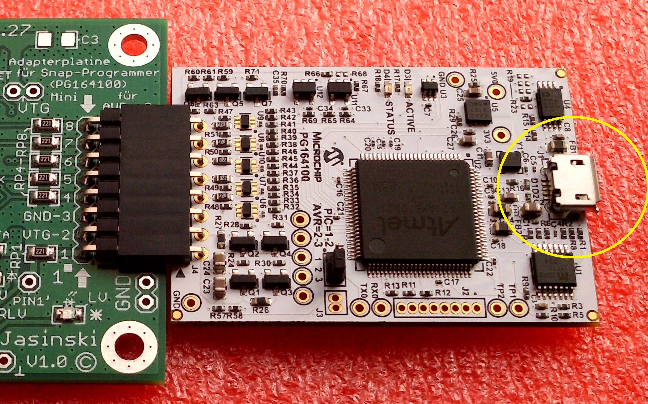
Bestückte Leiterplatte mit Atmel Mikrocontroller und USB-Anschluss
Adapterplatine für Snap-Programmer (PG164100) Mini für Atmel AVR PIC=1.2 T2.3 STATUS ACTIVE GND LV. GND U.V. Jasinski v1.0 R60 R61 R59 R74 R66 CC R68 D18 R19 R23 R43 R42 R65 R64 R67 U3 R28 R27 C26 C25 333 C8 F81 R50 R39 R48 R49 R47 R38 R37 R36 R35 R34 R33 R32 R31 R29 R24 R23 R30 R26 R57 R58 R13 R11 C17 J2 R12 R9 R3 R5 R2 C22 C21 C20 C19 C16 C15 C14 C13 C12 C11 C10 C9 C7 C6 C5 C4 C3 C2 C1
in „Entwurf USB-UART-Converter, KiCad, bitte um Review“ · Platinen · · Platinenfotos
-
PDF
schaltplan.pdf
1W 47R 1W MUX2 RC2 RC5 MUX1 R 4 RC3 RC4 +5V +5V ERDE Tastatur PIC18F2320(DIL28S) +5V 0 K20 2 K 2 1 R 1 R G2 G1 D5 SCL1 SDA1 D4 MUX4 R26 100 100 R27 MUX3 MUX2 MUX1 D3 D2 LL4148 +12V 2 1 LEDs C20 R 1 R 1 100nF ULN2003 +5V GND I²C K 5 R11 +12V SCL1 LED1 SDA1 R12 K18 RS232 LED2 R13 6 LED3 Jumper X2 +5V R14 C14 100nF C17 LED4 C1+ VCC R15 +5V C15 C1- V+ +5V LED5 K 100nF C2+ V- 100nF F R16 7 C2- GND C16 3 n LED6TX LED6TX T1IN T1OUT 100nF C 1 9 1 2 0 2 0 T2IN T2OUT n IC5 2 P R 1 R 1 RXD R1OUT R1IN 2 0 K 1 2 J R2OUT
in „Folgethread zu EMV-Stabilere Software? Hardwarebetrachtung!“ · Mikrocontroller und Digitale Elektronik ·
-
PDF
A200_MCP1407-EP_MIC.pdf
Typical Performance Curves (Continued) Note: Unless otherwise indicated, T = +A5°C with 4.5V <= V DD <= 18V. 150 120 VDD= 18V 1 MHz VDD= 18V 10,000 pF ) 125 ) 100 A A 6,800 pF t 100 ( 80 n 50 kHz n 1,000 pF r r u 75 100 kHz u 60 C 200 kHz C 2,500 pF p 50 500 kHz p 40 p p S 25 S 20 4,700 pF 0 0 100 pF 100
in „Treiber für IRF1404 ?“ · Mikrocontroller und Digitale Elektronik ·
-
PDF
Micrel.pdf
-1: ELECTRICAL CHARACTERISTICS (Note 1, Note 2) Electrical CharacteristiIN= VOUT + 1V;OUT = 10 mA; J = +25°C. Bold values indicate –40JC ≤ T ≤ +125°C, unless noted. Parameter Symbol Min. Typ. Max. Units Conditions –1 — 1 OUT = 10 mA Output Voltage VOUT –2 — 2 % 10 mA ≤ OUT≤ IFL (OUT + 1V) ≤ IN ≤26V
-
PDF
Ultraschallotrungssystem_Lego_Mindstorms.pdf
ausgestattet und¨eroffnet so viele Eins¨tzmoglichkeiten. 3.2.2 Beschreibung des PIC16F628 Der 16F628 geho¨t genau wie der 12F675 zu den Mid-Range PICs und ist diesem in vielen Belangen sehr¨ahnlich. Er v¨rfugt allerd¨ngs uber 18 Pins und mehr Speich¨r, dafur ist auch sein Stromverbrauch
in „Ortung mittels Ultraschall - Projektvorstellung / Hilfegesuch“ · Mikrocontroller und Digitale Elektronik ·
-
PDF
mindstorms.pdf
ausgestattet und¨eroffnet so viele Eins¨tzmoglichkeiten. 3.2.2 Beschreibung des PIC16F628 Der 16F628 geho¨t genau wie der 12F675 zu den Mid-Range PICs und ist diesem in vielen Belangen sehr¨ahnlich. Er v¨rfugt allerd¨ngs uber 18 Pins und mehr Speich¨r, dafur ist auch sein Stromverbrauch
in „Suche Transreceiver Ultraschallkapseln mit 80° Detektionswinkel“ · Mikrocontroller und Digitale Elektronik ·
-
 Bild
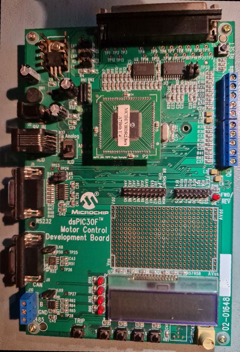
dsPIC30F Motor Control Development Board
MC9DEVBR2.14 A7B6h L4 TP1 TP2 TP3 TP4 TP5 TP6 TP7 TP8 TP9 TP10 TP11 TP12 TP13 TP14 TP15 R1 R2 R3 R4 R5 R6 R7 R8 R9 R10 R11 R12 R13 R14 R15 R16 R17 R18 R19 R20 R21 R22 R23 R24 R25 R26 R27 R28 R29 R30 R31 R32 R33 R34 R35 R36 R37 R38 R39 R40 R41 R42 R43 R44 R45 R46 R47
in „[V] ältere Demoboards PIC, NEC und Motor“ · Markt · · Platinenfotos
-
PDF
D865GBF_D865GLC_TechProdSpec.pdf
the computer before changing a jumper setting. Otherwise, the Desktop Board could be damaged. Figure 26 shows the location of the jumper blocks. A 1 2 9 10 J9A2 B 1 3 J9J4 OM15923 Item Description Reference Designator A Front panel audio connector/jumper block J9A2 B BIOS Setup configuration jumper block J9J4 Figure 26. Location of the Jumper Blocks 2.9.1 Front Panel Audio Connector/Jumper Block This connector has two functions: • With jumpers installed, the audio line out signals are routed to the back
in „VS: Intel D865GBF, Pentium 4 (3GHz/1M/800) SL7PM, Matrox G45“ · Markt ·
-
Datei
Testplatine.c
/* Testplatinenprogramm geschrieben von Mike Riedel Januar 2014 // Pinbelegung PIC 18F2420 RB7 RB6 RB5 RB4 RB3 RB2 RB1 RB0 VDD VSS RC7 RC6 RC5 RC4 | + ### ### ### ### ### ### ### ### ### ### ### ### ### ### + | | 28 27 26 25 24 23 22 21 20 19 18 17 16 15 | | +-+ | | | | | +-+ | |
in „Fehlerhafte Werte bei AD-Wandlung PIC18F2420“ · Mikrocontroller und Digitale Elektronik ·
-
PDF
EMS_V2_Schaltplan.pdf
JP5 A G G G T V RA4 22 RA2/AN2/VREF- RA5/AN4/SS/HLVDIN23 1 2 GND + RA3/AN3/VREF+ RA4/T0CKI 1 k7 C7 PIC18F4580_TQFP V 2 1 2 D4 1N4148SMD 2 7 1 2 2 FT245RL IC9 + 8 LCD R 100n RC3 6 SCL VCC 1 2 3 1 2 SJ7 7 WP M 3 4 RC0 = RS J2 D IC7 +5V GND O 5 6 RC1 = R/W 3 8 VIN VOUT 1 5 3 1 5 3 1 GND 3 A2 P aSDA 5 RC4
in „Buderus EMS-"Gateway" mit PIC18F / Sammelbestellung“ · Haus & Smart Home ·
-
PDF
TC4426.pdf
therefore outside the warranted range. Note: Unless otherwise indicated, T A = +25ºC with 4.5V ≤ V DD ≤ 18V. 100 100 2200 pF 2200 pF 80 80 1500 pF ) ) 1500 pF e e n 60 ( 60 ( 1000 pF L 1000 pF S A tR 40 tF40 470 pF 470 pF 20 20 100 pF 100 pF 0 0 4 6 8 10 12 14 16 18 4 6 8 10 12 14 16 18 V (V) V (V) DD DD
in „Mosfet Treiber TC4426 + IRF IRF3205S (Ersatz gesucht)“ · Analoge Elektronik und Schaltungstechnik ·
-
PDF
Grenzwerte_EMF.pdf
the potential carcinogenicity of 60 Hz linear sinusoidal continuous-wave magnetic fields in Fischer F344 rats, FASEB Jour- nal, 1997 (11), 1127-1136. Grenzwerte und Vorsorgemaßnahmen zum Schutz der Bevölkerung vor elektromagnetischen Feldern 41 [Man 00] Mandeville et al.: Evaluation of the Potential
in „2,455 Ghz Grill - Freund & Helfer gesucht“ · HF, Funk und Felder ·
-
PDF
MCP41HVX1.pdf
MAX) Hex Dec RS(MIN) R S(MAX) 00h 0 0.000 0.000 10h 16 16.314 24,471 20h 32 32.627 01h 1 1.020 1.529 11h 17 17.333 26.000 21h 33 33.647 02h 2 2.039 3.059 12h 18 18.353 27.529 22h 34 34.667 03h 3 3.059 4.588 13h 19 19.373 29.059 23h 35 35.686 04h 4 4.078 6.118 14h 20 20.392 30.588 24h - FFh 36 - 255 36.0
in „MCP41HVX READCMD falsch verstanden??“ · Mikrocontroller und Digitale Elektronik ·
-
PDF
MCP1700.pdf
. Load Voltage (V = 5R0V). Current (V R = 2.8V). 1.21 5.000 TJ= - 40°C VR= 1.2V VIN VR+ 1V 4.995 T J +25°C )1.20 ) ( (4.990 g1.19 T = +25°C g4.985 T = - 40°C t J t J o o4.980 V = 5.0V t1.18 t VR= V + 1V u u4.975 IN R t1.17 TJ= +125°C t4.970 O O 1.16 4.965 TJ= +125°C 4.960 1.15 4.955 0 25 50 75 100 125
in „ESP-01 mit LiPo betreiben“ · Mikrocontroller und Digitale Elektronik ·
-
PDF
LCD-Steuerung_-_ELV_05522_.pdf
C11 C12 C13 +5V R14 IC1 Schraubklemme 10n 10n 10n 10n 10n 10K 1 /RESET/PC6PC0/ADC0 24 +5V 16 ST1 15 ST2 mensschild an der Tür), RM3.67 ker ker ker ker ker PC1/ADC1 25 15 16 ST3 7 VCC PC3/ADC3 26 1 1 1 weshalb
-
PDF
mcp3424.pdf
Sample Rate Selection Bit 00 = 240 SPS (12 bits) (Default) 01 = 60 SPS (14 bits) 10 = 15 SPS (16 bits) 11 = 3.75 SPS (18 bits) bit 1-0 G1-G0: PGA Gain Selection Bits 00 = x1 (Default) 01 = x2 10 = x4 11 = x8 DS22088C-page 18 © 2009 Microchip Technology Inc. MCP3422/3/4 2 If the configuration byte is read
in „Sensorplatine MPX4115 DS1621 HIH5030 - Schaltungskontrolle“ · Mikrocontroller und Digitale Elektronik ·
-
PDF
klassed_facharbeit.pdf
Kondensatoren mit Polyester als P=I ⋅R S Dielektrikum verwendet, da diese billiger I270kHz A I2,2µF1A P270kHz0,4mW sind. Hier ist es nicht mehr notwendig I20kHz11,3 A I2,2µF5,7A P20kHz0,18W Polypropylen zu verwenden, da die Ströme Ptot,18 ausreichend klein sind (nur noch ca. 10mA). Die Toleranz ist
in „Suche Schaltplan für PWM Endstufe“ · Mikrocontroller und Digitale Elektronik ·
-
PDF
MCP2021.pdf
conditions: 1 nF; 1 k | 6.8 nF; 660 | 10 nF; 500 TH REC(MAX) = 0.284 x BB, TH DOM(MAX ) = 0.422 x BB, VBB =7.6V - 18V; BIT= 50 µs. D2 = tUS _REC(MAX ) / 2 BIT) Duty Cycle 3 @10.4 kbit/sec .417 — — %t BIT CBUS ;RBUS conditions: 1 nF; 1 k | 6.8 nF; 660 | 10 nF; 500 TH REC(MAX) = 0.778 x BB, TH DOM(MAX ) = 0.616 x BB, VBB =7.0V - 18V; BIT= 96 µs. D3 = BUS _REC(MIN) / 2 xBI) Duty Cycle 4 @10.4 kbit/sec — — .590 %t BIT CBUS ;RBUS
in „MCP2021 -> Welcher ESD Level wird erreicht“ · Mikrocontroller und Digitale Elektronik ·
-
PDF
enc28j60.pdf
Unicast destination address I C V V V L L - Multicast address - Broadcast address - Magic Packet™ 28 27 26 25 24 23 22 1 21 VDDOSC - Group destination addresses as defined by WOL 64-bit hash table SO 2 20 OSC2 SI 3 19 OSC1 - Programmable pattern matching of up to SCK 4 ENC28J60 18 VSSOSC 64 bytes at user-defined
in „ENC28J60 Resetpin“ · Mikrocontroller und Digitale Elektronik ·
-
PDF
MCP73871-Data-Sheet-20002090E__2_.pdf
MCP73871 Typical Application AC-DC Adapter or USB Port 18, 19 1, 20 System IN OUT Load 10 μF 2 4.7 μF VPCC 14, 15, 16 470 VBAT 6 4.7 μF PG NTC 470 7 STAT2 THERM 5 470 8 10 k STAT1 PROG1 R Single-Cell LBO 13 PROG1 Li-Ion Battery 3 SEL Low Hi 4 12 R PROG3
in „Fehlersuche beim MCP73871“ · Mikrocontroller und Digitale Elektronik ·
-
PDF
6291174.pdf
G 15 2 F 6 K 60 C 68 17 18 K _ E J1 C 4 C 3 F Z3 D T P 1 C J6 8 TE TE S H 1 G1 R 4 Y 1 6 1 E 19 10 K K V 3 I A 8 J 15 3 1E 1 E M CV N / C 64 2 5 1 2 I I C 6 5 V Z11 7 Z1 7 D V 7 1 1 R 0 6 1 06 1 I A P 0 1 0 1
in „Sanyo LCD Beamer PLC- XU30 defekt“ · Analoge Elektronik und Schaltungstechnik ·
-
PDF
s_p305_intel_mm_pro_p300.pdf
46 F0 46 *2 11 0 ) 0B 8B 45 F0 45 12 - _ 0C 8C 4E F0 4E 13 = + 0D 8D 55 F0 55 15 BkSp 0E 8E 66 F0 66 16 Tab 0F 8F 0D F0 0D 17 Q 10 90 15 F0 15 18 W 11 91 1D F0 1D 19 E 12 92 24 F0 24 20 R 13 93 2D F0 2D 21
in „LCD-Inverter kaputt - wer kann helfen?“ · PC Hard- und Software ·
-
PDF
MRF89XAM8A.pdf
SMT Murata GRM188R60J105KA 0603 01D C4 22 pF Capacitor, Ceramic, 50V, ±5%, UHI-Q NP0, Johanson Technology500R07S220JV4 SMT 0402 C5 1.8 pF Capacitor, Ceramic, 50V, ±0.1 pF, UHIJohanson Technology 500R07S1R8BV4 NP0, SMT 0402
in „Was darf man von einer PCB-Antenne erwarten?“ · HF, Funk und Felder ·
-
PDF
22070a-53890.pdf
-20 5 30 55 80 105 130 Temperature (°C) Temperature (°C) FIGURE 2-15: Line Regulation vs. FIGURE 2-18: Load Regulation vs. Temperature. Temperature. © 2007 Microchip Technology Inc. DS22070A-page 13 MCP1824/MCP1824S Note: Unless otherwise indicated, C = 4.7 µF Ceramic (X7R), C = 4.7 µF Ceramic (X7R),
in „[V] 50St.LowNoise Microchip LDO MCP1824T 3,3V/300mA SOT223-5 mit Shutdown“ · Markt ·
-
PDF
MCP73811_2.pdf
— 70 — mV Voltage Regulation (Constant-Voltage Mode) Regulated Output Voltage V 4.168 4.20 4.232 V PIC18FXXXX-2 REG 4.317 4.35 4.383 V PIC18FXXXX-3 4.367 4.40 4.433 V PIC18FXXXX-4 4.466 4.50 4.534 V PIC18FXXXX-5 VDD = [REG (typical)+1V] OUT = 10 mA T = -5°C to +55°C A Line Regulation |(ΔVBAT/ — 0.09
in „Hackbarer(?) 21 EUR Quadcopter“ · Mikrocontroller und Digitale Elektronik ·
-
PDF
MCP_73831.pdf
— 70 — mV Voltage Regulation (Constant-Voltage Mode) Regulated Output Voltage V 4.168 4.20 4.232 V PIC18FXXXX-2 REG 4.317 4.35 4.383 V PIC18FXXXX-3 4.367 4.40 4.433 V PIC18FXXXX-4 4.466 4.50 4.534 V PIC18FXXXX-5 VDD = [REG (typical)+1V] OUT = 10 mA T = -5°C to +55°C A Line Regulation |(ΔVBAT/ — 0.09
in „LiPo-IC MCP73831 kennt keine Ladeschlussspannung“ · Analoge Elektronik und Schaltungstechnik ·
-
PDF
SC16A_User_s_Manual.pdf
. Please follow step from b to f. k. Sample source code for PIC16F877A is compatible for PIC16F876A. Cytron Technologies developed based on PIC16F877A is because PICC Lite does not support PIC16F876A. Created by Cytron Technologies
in „Servomotor Steuerung per PIC“ · Mikrocontroller und Digitale Elektronik ·
-
Datei
NTC.html
NEbfVIbCITVVamDi0zcK6AogE6gAfA38DZ40xadYmUUDmfZjKwBEAY0yaiJzDdquqMrAh22Gz75P9s4YDwwGCg4OJiIjIWhcfH0/JkiXzPbhebEKs3fJrHaCvZs2aHDhwgBkzZtCpUycuXLhAWloacXFxfP/99yxevJh3330XsA1pnjmJ0Ztvvsnff//NnXfeSZ06dahZsyY//PADTz75JN26daNdu3bExcVhjCE+Ph5fX18SEhJIT08nLi6O5ORkOnXqREpKCr6+vgQFBfH333+zfv16unXrRmpqKgBdu3YlOTnZ6QMRJiUlXfJ36Azx8fFOj8FV5btuTDoVY36k5sHZeKfGscyjA2Pi7oXUkvRr4M0tVTzxyfiHjev
in „NTC auto kalibrierung - Matheformel“ · Mikrocontroller und Digitale Elektronik ·
-
PDF
70622B.pdf
15.249) regulatory standards. FIGURE 1: MRF89XA 32-PIN QFN PIN DIAGRAM 32-Pin QFN 4 3 ( I S R R R S C F E A V V D E N R T P D A V T 32 31 30 29 28 27 26 25 TEST5 1 TEST2 24 33 GND (1) TEST1 2 23 PLOCK VCORS 3 22 IRQ1 VCOTN 4 21 IRQ0 MRF89XA VCOTP 5 20 DATA PLLN 6 19 CLKOUT PLLP 7 SCK 18 TEST6 8 17 SDI
in „Wie genau funktioniert die drahtlose Kommunikation?“ · HF, Funk und Felder ·