bi-directional devices hRving V volts and underR the I limit is doubled. DS21503 Rev. 10 - 2 2 of 4 1.5KE6V8(C)A - 1.5KE400(C)A www.diodes.com 10,000 )p Ip Measured at ( 100 Peak Valpp I Zero Bias T F N ( R E R C 1000 U A C Half Valpp I /2 I S A L P U 50 C Measured at P ,T Stand-off Voltage A C E 100 , IP t p
MSR-Aufgaben kümmern muss: [c] The Cavli C17QS Cat 1bis module is designed with an ARM Cortex M3 processor operating at up to 306MHz clock speed, running on the FreeRTOS platform. With an iSIM variant under development, the module
of memories feature unsurpassed reliability and endurance, with up to 120 years of data retention at 85-degree Celsius, along with random access and full memory write at bus speeds. [/c] 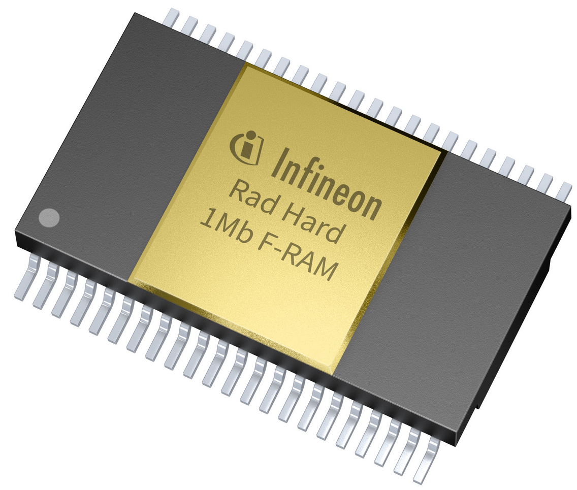 Bildquelle: https://www.infineon.com/cms/en/about-infineon/press/market-news
METEOSAT R Lentz, DL3WR 1978/3 173 174 Technology Reception 23 cm Band An Inexpensive Power Amplifier for 24 cm Using 2C39 U Mallwitz, DK3UC 1978/3 175 - 185 70 cm Band The Frequency Control Loop for a 433 MHz VCO T Krieg, DK8GY 1978/3 186 - 190 Oscillators A Frequency Control Loop for a 433 MHz VCO T Krieg
C256 oder C512 mit Fenster kann ich dir als LCC32 anbieten oder diverse Flashs als PLCC32.
Frank K. schrieb im Beitrag #7684763: >> Varianten als 27C32, 27C64 bzw. 27C128 bevorzugt. > > https://www.digikey.de/de/products/detail/microchip-technology/AT28C64B-15JU/1008523 > > Das ist ein EEPROM, also elektrisch löschbar. Wie gewünscht im PLCC32
1.3V to 3.6V X1 1 10 VCC • Low Typical Timekeeping Current: X X2 2 5 9 MFP - Operating from V: 1.2 µA at 3.0V 9 - Operating from VT: 1.0 µA at 3.0V VBAT 3 P 8 SCK • Automatic Switchover to Battery Backup CS 4 C 7 SO M VSS 5 6 SI User Memory • 64-Byte Battery-Backed SRAM • 1 Kbit or 2 Kbit EEPROM: Note:
) / 32768; amps = amps *1.333; //and if a 100amp / 50mv shunt is used amps = (rawResult * 256) / 32768; amps = amps *2; [/code] Ich nehme dann jetzt mal Bild 6 (Wert 112) 112 * 256 / 32768 = 0,875 0,875 * 1,333 = 1,166375 Also ~ 1,17 Ampere? Um demnach bei 24V 1,17 * 24
Englischen wird das V von Volt groß geschrieben. > Was ich gefunden habe sah immer wie folgt aus... [c] amps = (rawResult * 256) / 32768; amps = amps *1.333; [/c] Wo hast du diesen kruden Rechenweg gefunden? 1. (rawResult * 256) / 32768 ist das selbe wie rawResult / 128. Und wenn rawResult ein
aufgelistet: + Anschluss Nunchuk Pin Nunchuk Farbe Original Farbe Clone Pin STM32 1 Grün Gelb PB9 (SDA) 2 n.c. Schwarz n.c. 3 Rot Grün 3,3V 4 Weiß Rot GND 5 n.c. n.c. n.c. 6 Gelb Weiß PB8 (SCL) Da man in der Regel einen Clone erworben hat, kann man sich auf die Farben nicht verlassen. Besser ist es, den Stecker
different H/W & S/W configuration will result in different benchmark testing results.) System Benchmarks At DOS Environment with IDE Controller •CPU : AMD5 x6-133/ Cx5x86-100/ DX4-100 OVER/ Cx5x86-133/ AMD DX4-100 WB/ Cyrix DX4-100/ P24T-63 •DRAM : 8 MB / 60ns 2pcs. Total memory 16MB •CACHE : 256KB •VGA :
8GB eMMC 0 chip. Interestingly, this result is roughly 3× lower than the “back- 512 B 4 KiB 32 KiB 256 KiB 2 MiB 16 MiB I/O Block Size of-the-envelope” 3,000 complete rewrites one would expect to wear out the device [43, 62, 125]. Moreover, at a maximum throughput (b)Random Write of 20 MiB/s, one could
since the feeder set-up can 3 x 8 mm S b 1 2 mm 0.7 mm be changed quickly. 12/16 mm S 1 4 - 12 mm c 14 mm The increment of the tape cycle is just as variable as the use of tape Blister tape 24/32 mm S 1.5 4 - 32 mm c 14 mm materials. Thanks to the general 1 x 44 mm S 2.5 4 - 44 mm c 14 mm 1 x 56 mm
. PCA84C122AT/211 C84C122211D VIDEO MICROC.DERIV.80C48 CPU 935245160118 T S 3 31-3-01 30-6-01 See Comments. Can be replaced by 8521 Micro or PCA84C222/422/622. Consult Marketing. PCA84C122AT/212 C84C122212D VIDEO
offered in space- saving packages. The W25Q64FV array is organized into 32,768 programmable pages of 256-bytes each. Up to 256 bytes can be programmed at a time. Pages can be erased in groups of 16 (4KB sector erase), groups of 128 (32KB block erase), groups of 256 (64KB block erase) or the entire chip
funktioniert (24/7). Die Buslast war gering und die Reaktionszeit extrem kurz. Nur hat dann leider Philips/NXP seine 8051 mit I2C vollständig abgekündigt. Eine Umrüstung auf Atmel ATmega8 und AT89LP51RD2 ist dann
. Also auch die AT89C51xxx haben ernsthafte Macken. Ob sich das mit den ständig neuen AVR-Serien von Microchip verbessert hat, kann ich nicht sagen. https://www.robotroom.com/Atmel-AVR-TWI-I2C-Multi-Master-Problem.html
data, all data of the Configuration RAM are refreshed by the data in the Configuration EEPROM each 24 hours, at date increment (at the beginning of the last second before midnight). The time of this automatic refreshment is t = ~1.4 ms. AREFR Refresh is only active when RV-3032-C7 is not in VBACKUP
bekommen wir: [code]IN R24,0x05 ORI R24,0x04 OUT 0x05,R24 RETI [/code] Scheinbar wird das auch funktionieren, nur langsamer. In Wirklichkeit aber werden hier SREG und R24 in ISR geändert, das führt zu groben Programmfehler
tinyAVR 1-series of microcontrollers, using the 8-bit AVR processor with hardware multiplier, running at up to 20MHz and with 16KB Flash, 2KB of SRAM and 256B of EEPROM in a 14-, 20- and 24-pin package. The tinyAVR 1-series uses the latest technologies with a flexible and low power architecture including
Leider lässt du uns im Dunkeln bzgl. des Layouts/Verkabelung und der I2C Geräte, sowie den verwendeten I2C Parametern und des Programmcodes. 2K ist ein ungewöhnlicher Widerstandswert. Es gibt 2k Wiederstände, aber er ist nicht Teil der gebräuchlichen E12 und E24 Reihe
VCC, an internal power-on reset holds the TCA9548A in a reset condition until VCC has reached VPOR. At that point, the reset condition is released and the TCA9548A registers and I2C state machine initialize to their default states. After that, VCC must be lowered to below VPOR and then back up to the
protection exceeds 2000 V HBM per JESD22-A114, 150 V MM per JESD22-A115 and 1000 V CDM per JESD22-C101 Latch-up testing is done to JEDEC Standard JESD78 which exceeds 100 mA Packages offered: SO24, TSSOP24, HVQFN24 3. Ordering information Table 1. Ordering information Tamb = 40 C to +85 C. Type
übernimmt das Macintosh Projekt, beginnt eigentlich 01:05:25) https://www.youtube.com/watch?v=ErwS24cBZPc (der SuperBowl Werbespot für den Apple Macintosh)
Hier ist auch noch ein schöner Text: https://www.c64-wiki.de/wiki/Motorola_6809
0; i < Msg->Size; i++) { Serial.print(Msg->Data[i], BIN); } Serial.println(); } [/c] Pin wäre beim Nano 2 und denke beim ESP GPI04 oder täsuche ich mich?
electrical_standards_for_digital_command_control_2021.pdf Damit kann man seine eigene Erkennung schreiben, ganz ohne C++, wenn es denn sein muss. Apropos C++: so neu ist die Sprache auch nicht, ich benutze die seit 1991. Hätte man sich einarbeiten können. Dann könnte man auch Stummis Code verstehen. Der ist auch keine
pins, two on each side of the connector. To avoid confusion, the first two pins are defined as Pin C0 and Pin D0. The additional ground pins at the end of the connector are defined as C19 and D19. The pinout between PC/104 bus and AT ISA bus is identical between C1 - C18 and D1 - D18. The MOPS/386A
, ATmega2560, ATmega32u4, ATXmega128A3U, ATXmega256A3U, ATXmega384C3, ATXmega256D3, ATXmega384D3 und IC-Sockel; LEDS insbesondere auch RGB klar und diffuse als auch WS2812B auf Rolle;Powerinduktoren, Ferritkerne (auch Toroide) und Spulenkoerper, Ferritstaebe
Forum-Teilnehmer mit PLZ Wanderkiste (Widlar) mit PLZ Neue Wanderkiste Kittler mit PLZ Wanderkiste.at Austria, mit Ort Suche nach PLZ im Forum Lokale Elektroniklieferanten
interface. USB2.0 Interface, USB host and USB Device interface. SD/MMC card (SPI) interface. I2C Interface, connected to onboard 2Kbit EEPROM (24LC02). SPI serial interface connected to onboard 16Mbit Flash (AT45DB161D). 2 user keys, 2 function keys (INT0 and Reset button). 8 LED lights (Digital
at the protocol level. The SMBus clock is defined from 10 kHz to 100 kHz while I C can be 0 Hz to 100 kHz, 0 Hz to 400 kHz, 0 Hz to 1 MHz and 2 0 Hz to 3.4 MHz, depending on the mode. This means that an
connected to SS BS0, BS2, CL, D[7:3], E, R/W#, CS#, D/C#, BGGND Pin internally connected to DD: BS1, CLS V BAT,C1P, C1N, C2P, C2N, V BREF, FR should be left open. C1, C2: 2.2uF (1) (1) C3: 1.0uF R P Pull up resistor Voltage at REF = VCC – 2.5V. For VCC= 7.5V
knapp 1300 TWh. Nachfolgende Tabelle zeigt die im Szenariorahmen 2023-2037/2045 genehmigten Annahmen. 24 | GRUNDLAGEN DES PRÜFPROZESSES Installierte Leistung [GW] Referenz Szenario Szenario Szenario Szenario Szenario Szenario Energieträger 2020*/2021 A 2037 B 2037 C 2037 A 2045 B 2045 C 2045 Kernenergie
at core/timeouts.c line 241 0x40201047: updatePWM() at C:\Users\alex\Documents\Arduino\OhneFehler/OhneFehler.ino line 54 0x402014f4: Ticker::_static_callback() at C:\Users\alex\AppData\Local\Arduino15
0x401000ab: app_entry_redefinable() at C:\Users\alex\AppData\Local\Arduino15\packages\esp8266\hardware\esp8266\3.1.2\cores\esp8266\core_esp8266_main.cpp line 386 0x4010015c: ets_post(uint8, ETSSignal, ETSParam) at C:\Users\alex\AppData\Local
Der wichtigste Punkt bei FRAM ist immer noch die beschränkte Zyklenzahl. Cypress gibt z.B. beim FM24C16 10^12 Cycles an, kein Vergleich zu den bei Flash üblichen 10^5. Mit Wear Leveling kõnnte man im praktischen Einsatz noch mehr rausholen. Soul E. schrieb im Beitrag #7607697: > als RAM-Ersatz taugt
schrieb im Beitrag #7607718: >> Soul E. schrieb im Beitrag #7607697: >> Cypress gibt z.B. beim FM24C16 10^12 Cycles an, kein Vergleich zu den >> bei Flash üblichen 10^5. Mit Wear Leveling kõnnte man im praktischen >> Einsatz noch mehr rausholen. > > Richtig. Aber die 10^12 beim FRAN sind lesen
gesollt werden soll... ??? Wie alt bist Du? Korrektur: "...EINEN Film drehen" Aber nicht µC-net- Server mit so 'nem Müll belegen, auf YT bitte ! ! ! Infantilismus: "...Polo hat jetzt 256PS..." Der Sohn tot, im Zusammenhang mit Autos, manche kapieren's NIE! Die Dinger sind i.m.O.
Referenz“ am Beispiel eines Flash-Wandlers zwar schon des öfteren erwähnt, jedoch im DB des AT328P steht: 24.2 Overview The ATmega48A/PA/88A/PA/168A/PA/328/P features a 10-bit successive approximation ADC Was denn auch sonst... Flash-Wandler pfffft mfG fE
details of physical dimension are: • The tick marks are placed on a 270 degree arc, clockwise starting at south-west position • Minor ticks are lines of width r*(2/256), major r*(6/256) • Ticks are drawn at a distance of r*(190/256) to r*(200/256) • The pointer is drawn with lines of width r*(4/256), to
