Suchergebnisse für "ESP32C3"
change to longer) String sync ="21A4"; // the syncword in a RF-stream for kinetic switches... String c 1[2] = {"C 46A01", "EF3 B04"}; // three hex values for a indentifier kinetic-button ('C 46A' is kinetic switch ID (from the swicht backside label), next hex value is the button-id ) String c 2[2] = {"C 46A02
in
„2-/3-fach kinetic switch an ESP8266 (Arduino)“
·
Haus & Smart Home
·
28.11.2023 09:02
Bild
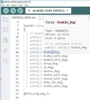
ESP 32 C 3 _GPIO | Arduino IDE 2.3 .3
ESP 32 C 3 _GPIO.ino
typedef struc
// mapped
uint32 _t uint32 _t uint32 _t Enable_Reg;
uint32 _t Enable_W1TS_Reg;
uint32 _t Enable_W1TC_Reg;
uint32 _t Strap_Reg;
uint32 _t In_Reg;
uint32 _t Status_Reg;
uint32 _t Status_W1TS_Reg;
uint32 _t Status_W1TC_Reg;
uint32 _t PCPU_Int_Reg;
uint32 _t Status_Next_Reg;
}GPIO_Cnfg_Reg;
in
„C > Struct > Pointer - Adresszuweisung“
·
Mikrocontroller und Digitale Elektronik
·
12.10.2024 11:07
·
Screenshots
Bild
main.cpp ESP 32 _LORA_Sender src main.cpp ESP 32 _GPIO src platformio.ini ESP 32 _S3 _Test panic_abort.dbgasm 0x40377048 entry a1, 32 0x4037704b4 132r a8, 0x4037478c 0x4037704e movi.n a9, 1 0x40377050 s8i a9, a8, 0 0x40377053 132r a8, 0x40374790 0x40377056 s32 i.n a2, a8, 0 0x40377058 movi.n a8, 0 0x4037705a c 0 20 00 memw 0x4037705d s32 i.n a8, a8, 0 0x4037705f f0 41 00 break 1, 15
in
„ESP32-S3-ZERO debugging“
·
Mikrocontroller und Digitale Elektronik
·
19.02.2025 14:01
·
Screenshots
(5) #define MAX_RF_PAYLOAD_SIZE (32 ) #ifdef ESP 8266 #define PACKET_BUFFER_SIZE (30) #else #define PACKET_BUFFER_SIZE (20) #endif // Startup defaults until user reconfigures it #define DEFAULT_RECV_CHANNEL (3 ) // 3 = Default channel for
in
„Wechselrichter Hoymiles HM-xxxx 2,4 GhZ Nordic Protokoll?“
·
Mikrocontroller und Digitale Elektronik
·
15.08.2022 19:00
(5) #define MAX_RF_PAYLOAD_SIZE (32 ) #ifdef ESP 8266 #define PACKET_BUFFER_SIZE (30) #else #define PACKET_BUFFER_SIZE (20) #endif // Startup defaults until user reconfigures it #define DEFAULT_RECV_CHANNEL (3 ) // 3 = Default channel for
in
„Wechselrichter Hoymiles HM-xxxx 2,4 GhZ Nordic Protokoll?“
·
Mikrocontroller und Digitale Elektronik
·
15.08.2022 21:17
Bild
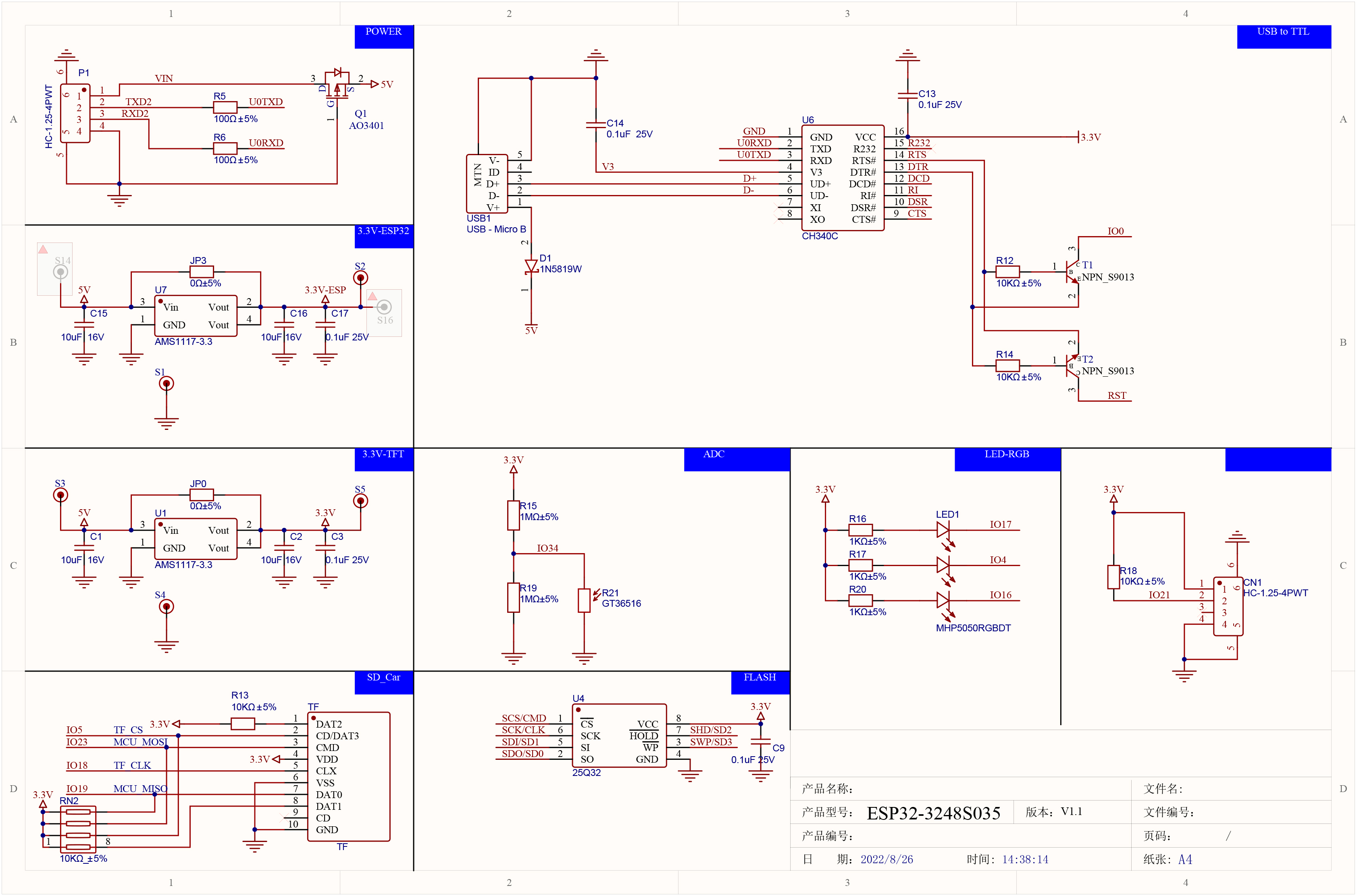
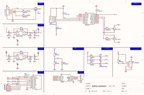
POWER VIN TXD2 RXD2 1000±5% U9TXD U8 USB1 USB-Micro B V3 C 14 0.1uF 25V GND U9TXD R232 3 .3 V TXD 13.3 V D+ D- 6 UD- R11 12 RXD 10 DS# 9 CTS# CH340C 3 .3 V-ESP 32 3 .3 V U7 Vin C 15 10uF 16V C 16 10uF 16V C 17 0.1uF 25V AMS1117-3 .3 3 .3 V-TFT 3 .3 V ADC R15 1MΩ±5% LED1 IO17 R16 1KΩ±5% R20 1KΩ±5% IO16 R18 10KΩ±5% IO21 C 1 R4 C 2 C 3 0.1uF 10uF 16V GND IO34 SD_Card 3 .3 V R13 10KΩ±5% TF IO5 IO23 IO18 TF R32 10KΩ±5% 8 TF SD_Card U4 25Q32 SCK/CLK CMD SDDSD SDDSD GND WP CS XCS SHD/SD SWP/SD C 9 0.1uF ESP 32 -3248S038
in
„Cheap Yellow Display“
·
Mikrocontroller und Digitale Elektronik
·
30.05.2024 10:18
·
Schaltpläne
(5) #define MAX_RF_PAYLOAD_SIZE (32 ) #ifdef ESP 8266 #define PACKET_BUFFER_SIZE (30) #else #define PACKET_BUFFER_SIZE (20) #endif // Startup defaults until user reconfigures it #define DEFAULT_RECV_CHANNEL (3 ) // 3 = Default channel for
in
„Wechselrichter Hoymiles HM-xxxx 2,4 GhZ Nordic Protokoll?“
·
Mikrocontroller und Digitale Elektronik
·
14.08.2022 11:01
for more information. Arduino Micro Section common to all radino modules 15 GPIOs HUID Keyboard I²C ATmega32 U4 USB HUID Mouse UART UART MISO,MOSI,SCK for radio communication:served IO8,IO9,D4,D7 SPI-UART bridge WiFi ESP 8266 Radio Section –WiFi In-Circuit GmbH Boltenhagener Str. 124 Document-Nr: 3051000
in
„Wlan2Serial Modul für 5 euro“
·
Mikrocontroller und Digitale Elektronik
·
28.10.2014 15:03
R4 8 GND URXD 5 RX P1 P* G A 19 5 71D 7-Segment 1 - D 1 10k R5 GND RA3 6 72A 7-Segment 2 -A ESP 1 ESP PIC R6 Pololu S7V8F3 10k RA4 7 LED2 LED2 R7 100 ESP _INFO 10k GND GND RA5/SS1 9 72B 7-Segment 2 - B Flash GND GND ICSPDAT 28 RA7 10 72C 7-Segment 2 - C E-RST ICSPCLK 27 RB7
in
„PICKIT3 - Target Halted nach Zuschaltung von Schaltregler“
·
Mikrocontroller und Digitale Elektronik
·
19.12.2017 22:13
Schaltsignal • Digital: Rückkanal, als OC oder seriell • Arduino-Belegung je Kanal, mit zusätzlichem I2C -A/D-Wandler ADS1115 für die Spannungsmessung Signal K1 K2 K3 K4 Schalt D4 D5 D6 D7 Spannung A0 A1 A2 A3 Strom ADS0 ADS1 ADS2 ADS3 Rückkanal D8 D9 A6 A7 • Kommunikationsvarianten o Serielle Schnittstelle
in
„Hutschienen Arduino“
·
Mikrocontroller und Digitale Elektronik
·
19.05.2017 21:02
102 Rack 0 Slot 2 ESP 32 : Asynchroner Webserver Automatische LOGO!-Wiederverbindung VW0 wird alle 500 ms gelesen ============================================================ BENÖTIGTE LIBRARIES ===========================
in
„mit ESP32 LOGO 8 VM Block lesen“
·
Mikrocontroller und Digitale Elektronik
·
30.09.2026 11:56
IO4 25 GPIO0 15 IO12 IO0 24 D9 R1 D7 16 GND IO2 23 A4 2.4K D5 17 IO13 IO15 22 SD1 SD2 SD1 D6 18 SD3 SD0 21 SD0 CMD 19 CMD CLK 20 CLK GND ESP 32 C C U4 VB J1 R6 4 5 USBVCC C 7 8 VCC BAT 1 C 8 + 0.1R R15 7 CE TEMP 2 R16 - 6 CHRG PROG 3 2.4K BAT 10uF 2.4K STDBY GND 10uF TP4056 USBVCC VB D2 R10 VCC 3 V3 0R Q3 SI2301 U5 VB 1 VIN VOUT 5 R20 C 13 3 C 12 C 10 C 11 1M EN R11 A0 FD1 FD2 FD3 FD4 47uF 2 GND SNS/NC 4 47uF 47uF 100nF C 4 R21 0R D RT9080-33GJ5 100nF 1M D USBVCC Title: FireBeetleBoard-ESP 32 SKU: DFR0478 Drawn
in
„Funktion des Schaltplans“
·
Analoge Elektronik und Schaltungstechnik
·
16.03.2022 18:01
Bild
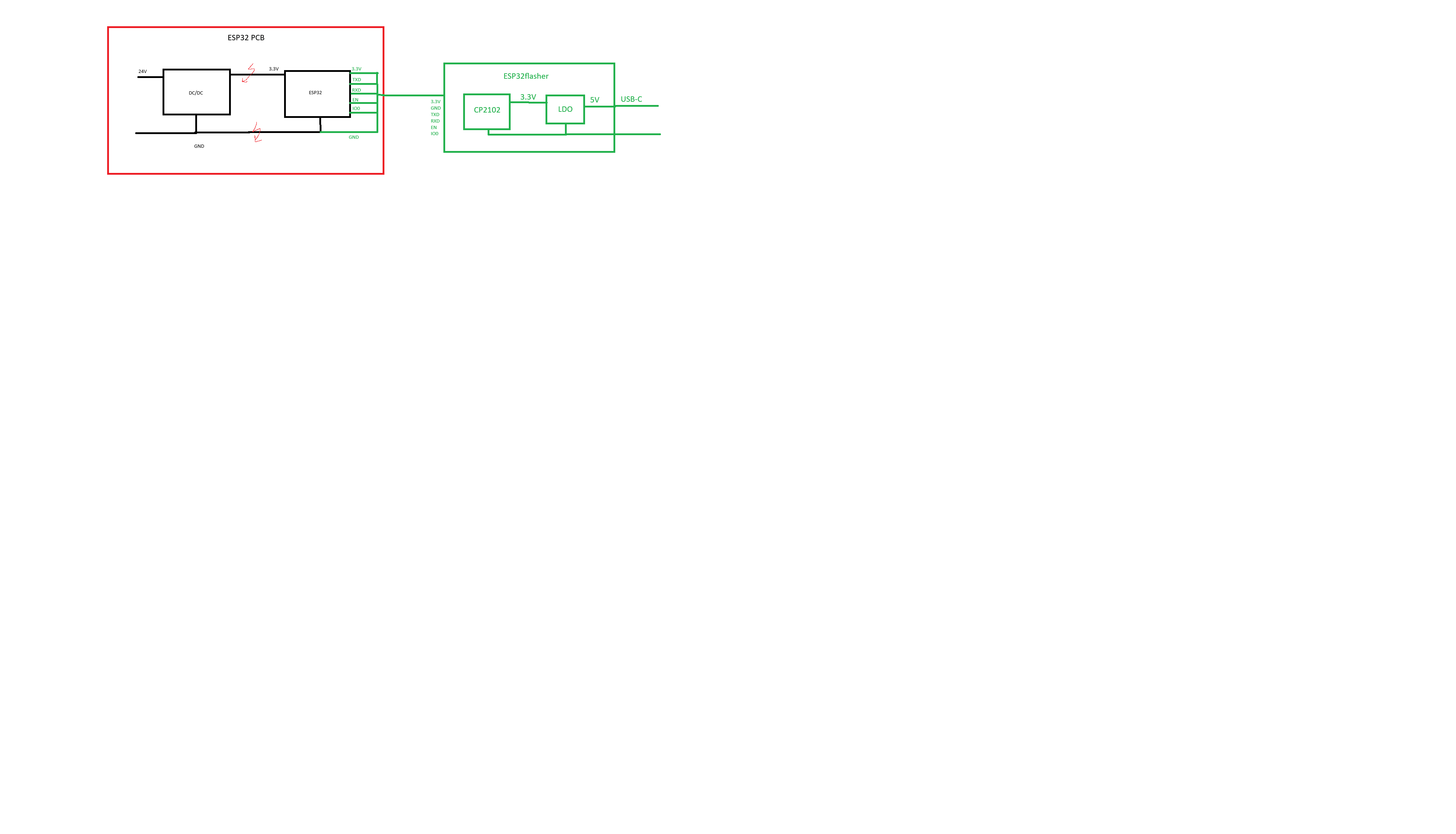
ESP 32 PCB
3 .3 V
3 V3
EN
IO0
IO1
IO3
GND
ESP 32
ESP 32 flasher
CP2102
3 .3 V
LDO
USB-C
in
„Vermischte Potentiale“
·
Mikrocontroller und Digitale Elektronik
·
12.11.2025 22:25
·
Schaltpläne
AVR_ATmega2560__) int inputPins[] = {A0, A1, A2, A3 , A4, A5, A6, A7, A8, A9, A10, A11, A12, A13, A14, A15, 2, 3 , 4, 5, 6, 7, 8, 9, 10, 11, 12, 13, 14, 15, 16, 17, 18, 19, 22, 23, 24, 25, 26, 27, 28, 29, 30, 31, 32 , 33, 34, 35, 36, 37, 38, 39, 40, 41,
in
„Dauerkontakt vom Schalter in Impuls umwandeln“
·
Analoge Elektronik und Schaltungstechnik
·
02.01.2024 20:15
www.youtube.com/watch?v=oCMOYS71NIU Based on Neil Kolban example for IDF: https://github.com/nkolban/esp 32 -snippets/blob/master/cpp_utils/tests/BLE%20Tests/SampleNotify.cpp Ported to Arduino ESP 32 by Evandro Copercini updated by chegewara Create a BLE server that, once we receive a connection, will send periodic notifications. The service advertises itself as: 4fafc201-1fb5-459e-8fcc-c 5c 9c 331914b And has a characteristic of: beb5483e-36e1-4688-b7f5-ea07361b26a8 The design of creating the BLE server is: 1. Create a BLE Server 2. Create a BLE Service 3 . Create a BLE Characteristic on
in
„ESP32 D1 MINI als Bluetooth Master“
·
Mikrocontroller und Digitale Elektronik
·
16.08.2021 10:27
Bild
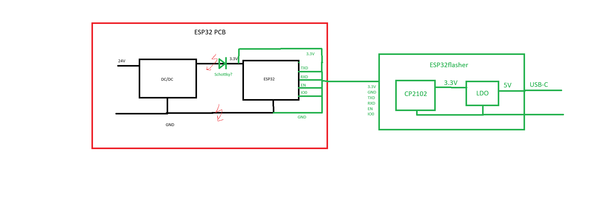
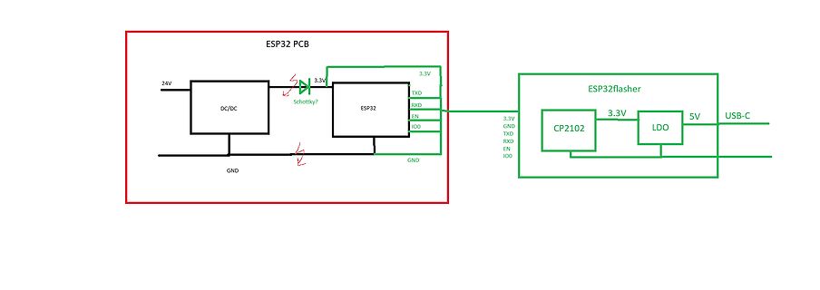
ESP 32 PCB 24V DC/DC Schottky? 3 .3 V ESP 32 TXD RXD IO0 GND GND 3 .3 V ESP 32 flasher CP2102 3 .3 V LDO 5V USB-C GND TXD RXD EN IO0
in
„Vermischte Potentiale“
·
Mikrocontroller und Digitale Elektronik
·
12.11.2025 22:36
·
Schaltpläne
Bild
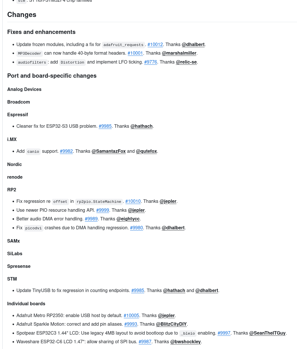
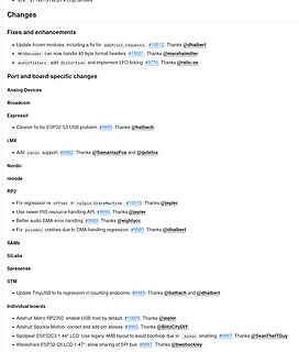
Broadcom
Espressif
Cleaner fix for ESP 32 -S3 USB problem. #9985. Thanks @hathach.
i.MX
Add canio support. #9982. Thanks @SamantazFox and @qutefox.
Nordic
renode
RP2
Fix regression re offset in rp2pio.StateMachine. #10010. Thanks @jepler.
in
„EtherCAT, CircuitPython, OpenWRT und ein quelloffenes TPM“
·
Mikrocontroller und Digitale Elektronik
·
10.02.2025 13:47
·
Screenshots
// http://br-b5aktuell-live.cast.addradio.de/br/b5aktuell/live/mp3 /128/stream.mp3 int hilf=strlen(getanfragehttp); printf("anfragelaenge: %i",hilf); ////http:// /b5aktuell_2.m3 u //<<<<<<<<<<<<<<<<<<<<<<<< ESP Initialisieren >>>>>>>>>>>>>>>>>>>>>>>>>>>>>>>>>> /*HAL_UART_Transmit
in
„ESP8266 Webradio Stream“
·
Mikrocontroller und Digitale Elektronik
·
05.09.2017 21:37
Bild
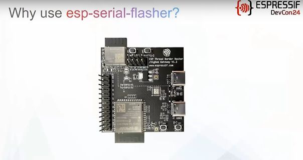
Why use esp -serial-flasher? ESPRESSIF DevCon24 ESP Thread Border Router / Zigbee gateway V1.2 www.espressif.com RESET1 RESET2 ESP 32 -C 3 ESP 32 -S3 USB1 USB2 USB3
in
„Made by Developers, Made For Developers – ESP32 DevCon, Tag 1“
·
Mikrocontroller und Digitale Elektronik
·
03.09.2024 22:32
·
Platinenfotos
Bild
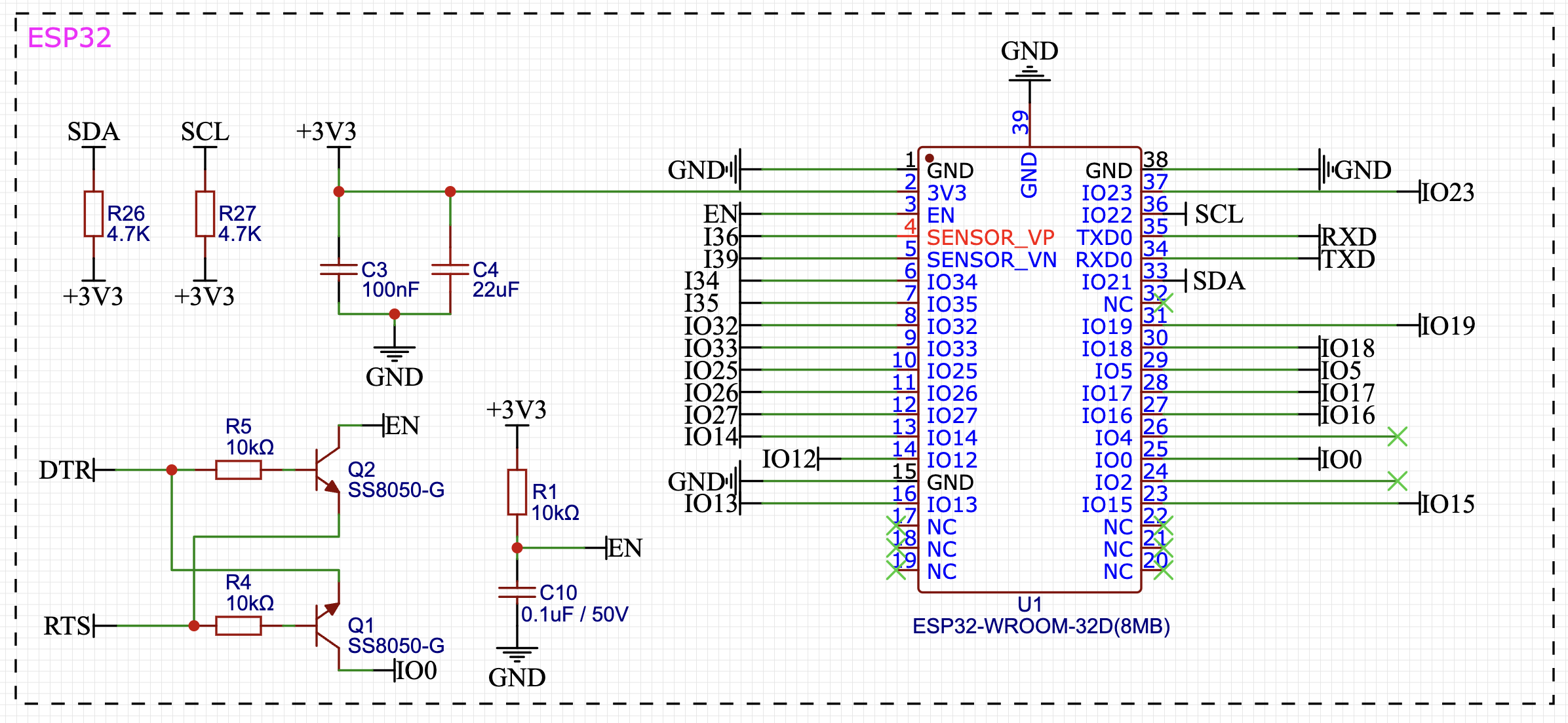
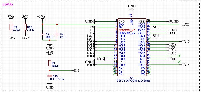
ESP 32 SDA SCL +3 V3 R26 2.2kΩ R27 2.2kΩ +3 V3 C 3 100nF C 4 22uF GND +3 V3 GND +3 V3 R1 10kΩ EN C 10 0.1uF / 50V GND U1 ESP 32 -WROOM-32 D(8MB) GND IO13 IO12 IO14 IO27 IO26 IO25 IO33 IO32 IO33 IO32 IO31 IO30 IO29
in
„Es wird nur ein I2C Gerät erkannt“
·
Mikrocontroller und Digitale Elektronik
·
02.05.2024 16:17
·
Schaltpläne
/***************************************** ****************************************** ** ** ** ESP 8266_WiFI_UDP_Server_OLED.ino ** ** ** ****************************************** *****************************************/ #include <Arduino.h> #include <ESP 8266WiFi.h> #include <WiFiUDP.h> #include
in
„UDP-Netzwerke(l)n mit kleinen Mikrocontrollern und WizNet W5100/W5500“
·
Mikrocontroller und Digitale Elektronik
·
12.02.2026 21:22
Bild
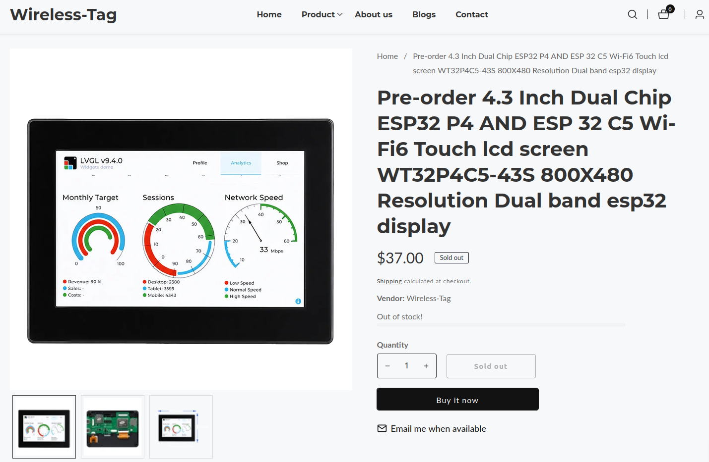
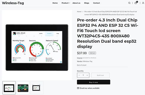
Wireless-Tag Home Product About us Blogs Contact Pre-order 4.3 Inch Dual Chip ESP 32 P4 AND ESP 32 C 5 Wi-Fi6 Touch lcd screen WT32 P4C 5-43S 800X480 Resolution Dual band esp 32 display $37.00 Sold out Shipping calculated at checkout. Vendor: Wireless-Tag Out of stock
in
„Littelfuse kündigt Mikrocontroller ab, Qualcomm äußert sich zu Arduino uvam“
·
Mikrocontroller und Digitale Elektronik
·
13.10.2026 19:14
·
Screenshots
Timer_timeout_Maxvalue 3000 #define HEXCODE_BIT1_READ_SENSOR_1 0x31 #define HEXCODE_BIT1_READ_SENSOR_2 0x32 #define HEXCODE_BIT1_READ_SENSOR_3 0x33 #define HEXCODE_BIT1_WRITE_CHANNEL_1 0x31 #define HEXCODE_BIT1_WRITE_CHANNEL_2 0x32 #define HEXCODE_BIT1_WRITE_CHANNEL_3 0x33 #define HEXCODE_BIT1_READ_DEBUG 0xFF
in
„mehrere Zeichen per UART empfangen“
·
Mikrocontroller und Digitale Elektronik
·
26.02.2026 12:45
Bild
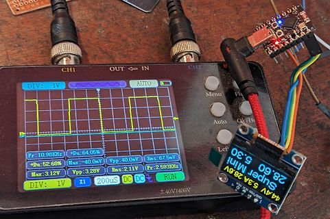
CH1 OUT IN CH2 DIV: 1V AUTO Menu Fl Auto Ok/Ho Left Fr: 10.98KHz +Du: 64.05% Vpp: 40.0mV Rms: 67.5mV +Du: 52.68% Max: -40.0mV Vpp: 3.28V Rms: 2.11V Max: 3.12V Fr: 2.593KHz DIV: 1V X1 200uS DC DC RUN ±40V/400V Super Mini 44.4V 5.3A 28.6V 5.3A 28.6V GND VCC 3V3
in
„Wie 20-40A high side (n-Ch 2,4 mOhm) bei 20-60V und 2 kHz 50% duty pwm ?“
·
Analoge Elektronik und Schaltungstechnik
·
29.04.2024 18:11
·
Fotos
#include <SPI.h> const int CS_PIN = 10; void setup() { Serial.begin(115200); pinMode(CS_PIN, OUTPUT); digitalWrite(CS_PIN, HIGH); // CS auf High, wenn nicht aktiv SPI.begin(6, 2, 7); // SCK, MISO, MOSI SPI.beginTransaction(SPISettings(1000000, MSBFIRST, SPI_MODE0)); // Max. 1 MHz wie empfohlen //Soft-Reset writeRegister(0x2A, 0b00000010); uint16_t softReset = readRegister(0x26); Serial.print("Soft-Reset: "); Serial.println(softReset); //Modus-Wahl writeRegister(0x26, 0b00000000); //Standby-Mode uint16_t mode1 = readRegister(0x26); Serial.print("Mode_1: "); Serial.println(mode1); writeRegister(0x27, 0b11100000
in
„ADXL380 mit SPI auslesen“
·
Mikrocontroller und Digitale Elektronik
·
29.07.2025 11:36
Bild
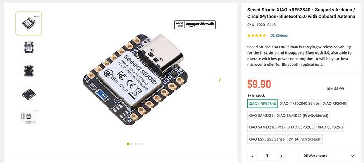
XIAO nRF52840 XIAO nRF52840 Sense XIAO RP2040 XIAO SAMD21 XIAO SAMD21 (Pre-Soldered) XIAO SAMD21 (3 Pcs) XIAO ESP 32 C 3 XIAO ESP 32 S3 XIAO ESP 32 S3 Sense D1 (4-Inch Screen DE Warehouse
in
„Nachrichten-Allerlei: neue Entwicklerboards, Meadow-Update uvm“
·
Mikrocontroller und Digitale Elektronik
·
31.08.2023 22:57
·
Screenshots
, /* reset=*/ U8X8_PIN_NONE); // ESP 32 Thing, pure SW emulated I2C //U8G2_SSD1306_128X64_NONAME_1_HW_I2C u8g2(U8G2_R0, /* reset=*/ U8X8_PIN_NONE, /* clock=*/ 16, /* data=*/ 17); // ESP 32 Thing, HW I2C with pin remapping //U8G2_SSD1306_
in
„Fragen zu Waveshare e-paper 1.54"“
·
Mikrocontroller und Digitale Elektronik
·
08.01.2022 17:17
Bild
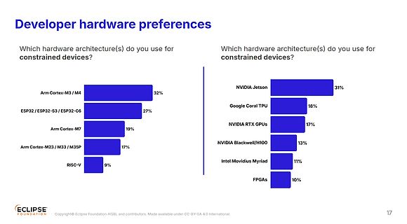
hardware preferences
Which hardware architecture(s) do you use for constrained devices?
Arm Cortex-M3 / M4 32 %
ESP 32 / ESP 32 -S3 / ESP 32 -C 6 27%
Arm Cortex-M7 19%
Arm Cortex-M23 / M33 / M35P 17%
RISC-V 9%
NVIDIA Jetson 31%
Google Coral TPU 18%
NVIDIA RTX GPUs 17%
NVIDIA Blackwell/H100 13%
Intel Movidius
in
„Arduino Ventuno Q, Marktanalyse des Embeddedbereichs, neue Chips uvam“
·
Mikrocontroller und Digitale Elektronik
·
09.03.2026 16:53
·
Diagramme
SPI_LL_TRANS_LEN_COND_WRDMA = BIT(2), ///< WRDMA length will be recorded SPI_LL_TRANS_LEN_COND_RDDMA = BIT(3 ), ///< RDDMA length will be recorded } spi_ll_trans_len_cond_t; // SPI base command in esp 32 c 3 typedef enum { /* Slave HD Only */ SPI_LL_BASE_CMD_HD_WRBUF = 0x01, SPI_LL_BASE_CMD_HD_RDBUF = 0x02, SPI_LL_BASE_CMD_HD_WRDMA
in
„C > Struct > Pointer - Adresszuweisung“
·
Mikrocontroller und Digitale Elektronik
·
10.11.2024 11:50
Bild
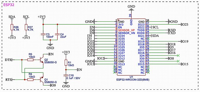
ESP 32 , SDA, SCL, +3 V3 , R26 4.7K, R27 4.7K, C 3 100nF, C 4 22uF, GND, EN, I36, SENSOR_VP, I34, SENSOR_VN, I35, IO34, IO32 , IO33, IO25, IO32 , IO26, IO27, IO14, IO12, IO13, IO23, IO22, SCL, TXD0, RXD0, TXD,
in
„ESP32 automatischer Start und Flash“
·
Mikrocontroller und Digitale Elektronik
·
02.05.2024 21:33
·
Schaltpläne
GND GND GND GND JP14 SPK GND IC1 mit LDR: R1 bestücken mit TSOP: R5, C 1 bestücken VB 1 40 STM32 _3 V3 _2 R2 frei lassen R16 frei lassen C C 13 2 39 GND ohne TSOP: R5, C 1 frei lassen S1 JP13 C C 14 3 38 +5V ohne LDR: R1 frei lassen R16 bestücken WPS 3 C 15 4 37 B9 3 R2 bestücken
in
„WordClock mit WS2812“
·
Projekte & Code
·
25.01.2026 10:24
/ 16, /* data=*/ 17); // ESP 32 Thing, HW I2C with pin remapping //U8G2_SSD1306_128X64_NONAME_F_6800 u8g2(U8G2_R0, 13, 11, 2, 3 , 4, 5, 6, A4, /*enable=*/ 7, /*cs=*/ 10, /*dc=*/ 9, /*reset=*/ 8); //U8G2_SSD1306_128X64_NONAME_F_8080
in
„ST7567 Display falsch mit Arduino Nano verbunden?“
·
Mikrocontroller und Digitale Elektronik
·
09.07.2018 12:56
verfügbar. Seite 5 Projekt VRS-Replace / © M. Lange / https://github.com/kleinekuh/vrsreplace / GPL v3 Bauteile Folgende elektronischen Bauteile wurden für die Umsetzung verwendet. Anzahl Bauteile 1 ESP 32 DevKit C (siehe Bild) 1 SD Card Modul 1 0,96‘‘ I2C Display (nicht unbedingt notwendig, sieht aber
in
„Regelung Solarthermie - Ersatz für auroMATIC 560“
·
Projekte & Code
·
19.04.2025 12:16
Bild
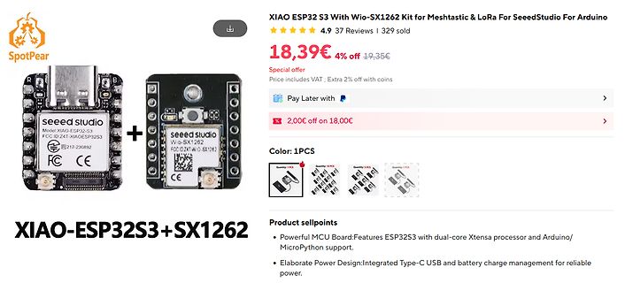
SpotPear XIAO ESP 32 S3 With Wio-SX1262 Kit for Meshtastic & LoRa For SeeedStudio For Arduino 4.9 37 Reviews | 329 sold 18,39€ 4% off 19,35€ Special offer Price includes VAT; Extra 2% off with coins Pay Later with 2,00€ off on 18,00€ Color: 1PCS XIAO-ESP 32 S3 +SX1262 Product sellpoints • Powerful MCU Board: Features ESP 32 S3 with dual-core Xtensa processor and Arduino/ MicroPython support. • Elaborate Power Design: Integrated Type-C USB and battery charge
in
„AI-VNA, 6GHz-Oszilloskop von Rigol, NEC-Frontend uvam“
·
Mikrocontroller und Digitale Elektronik
·
15.06.2026 11:03
·
Screenshots
Bild
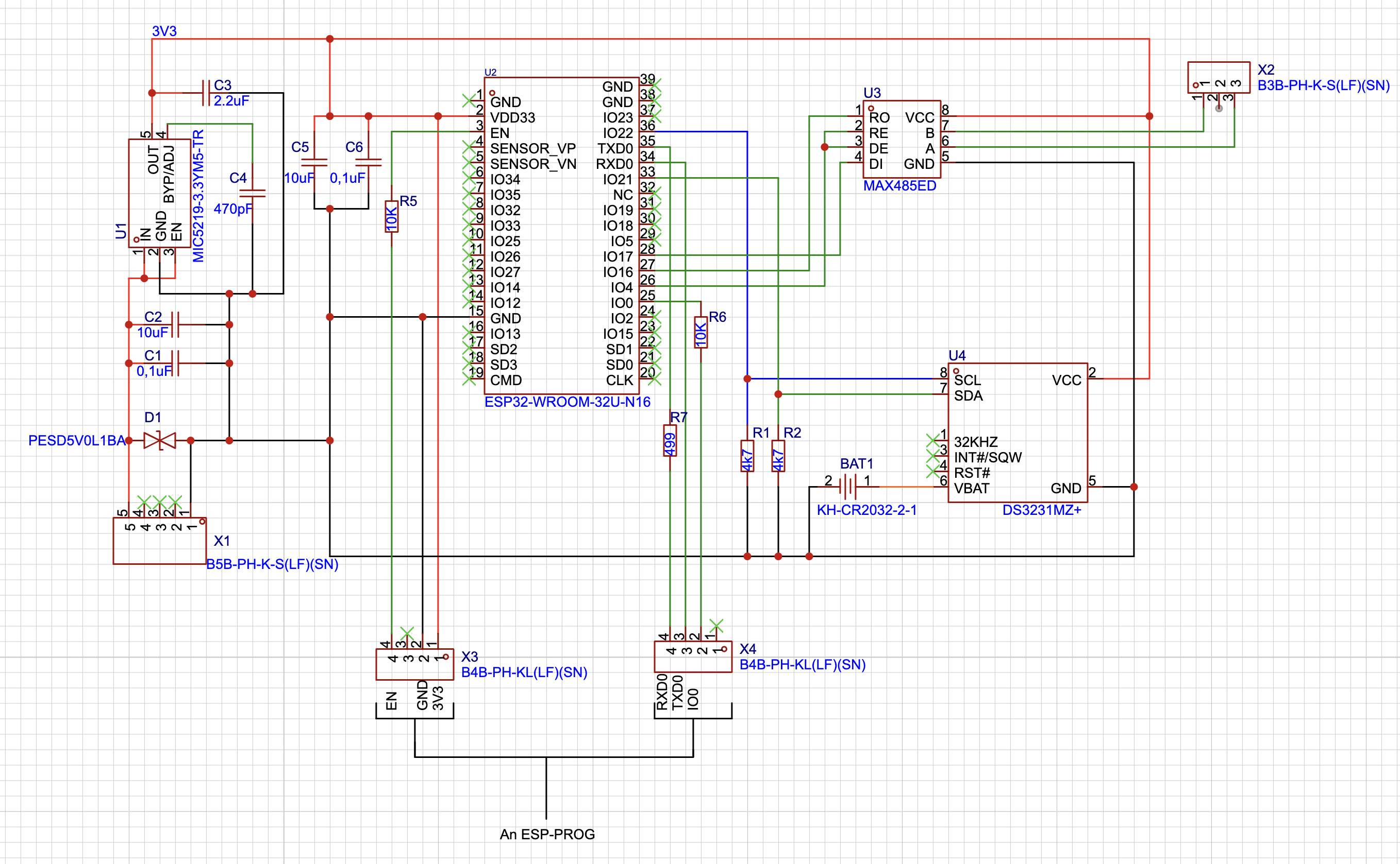
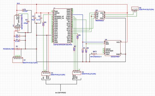
, SD0, CMD, ESP 32 -WROOM-32 U-N16, R5 10K, R6 10K, R7 10K, U3 MAX485ED, RO, RE, DE, DI, A, B, GND, VCC, X2 B3 B-PH-K-S(LF)(SN), U4 DS3231MZ+, SCL, SDA, VCC, 32 KHz, INT#/SQW, RST#, VBAT, BAT1, KH-CR2032-2-1, R1, R2, X1 B5B-PH-K-S(LF)(SN), D1 PESD5V0L1BA, C 1 0,1uF, C 2 10uF, C 4 470pF, C 5, C 6, X3 B4B-PH-KL(LF)(SN), X4 B4B-PH-KL(LF)(SN), EN, GND, 3 V3 , RXD0, TXD0, IO0, An ESP -PROG
in
„Probleme beim flashen des ESP32 mit ESP-PROG“
·
Mikrocontroller und Digitale Elektronik
·
18.11.2024 17:51
·
Schaltpläne
Configuration 0x59, // FSTEST Frequency Synthesizer Calibration Control, 0x7F, // PTEST Production Test 0x3 F, // AGCTEST AGC Test 0x81, // TEST2 Various Test Settings 0x3 F, // TEST1 Various Test Settings 0x0B // TEST0 Various Test Settings }; void setup(){ #ifdef ESP 32 gdo0 = 2; // for esp 32 ! GDO0 on GPIO pin 2. #elif ESP 8266 gdo0 = 5; // for esp 8266! GDO0 on pin 5 = D1. #else gdo0 = 6; // for Arduino! GDO0 on pin 6. #endif Serial.begin(9600); Serial.println("Rx"); ELECHOUSE_cc1101.Init(); for (int i = 0; i<47; i++){
in
„ESP8266 Wemos D1 & CC1101“
·
Mikrocontroller und Digitale Elektronik
·
12.04.2020 15:12
CC build/coap/port/coap_io_socket.o AR build/coap/libcoap.a AR build/console/libconsole.a CC build/esp -tls/esp _tls.o CC build/esp -tls/esp _tls_mbedtls.o AR build/esp -tls/libesp-tls.a AR build/esp -wolfssl/libesp-wolfssl.a CC build/esp 8266/driver/adc.o CC build/esp 8266/driver/i2c .o CC build/esp 8266/driver
in
„flash esp8266“
·
Mikrocontroller und Digitale Elektronik
·
19.08.2020 19:45
(5) #define MAX_RF_PAYLOAD_SIZE (32 ) #ifdef ESP 8266 #define PACKET_BUFFER_SIZE (30) #else #define PACKET_BUFFER_SIZE (20) #endif // Startup defaults until user reconfigures it //#define DEFAULT_RECV_CHANNEL (3 ) // 3 = Default channel for
in
„Wechselrichter Hoymiles HM-xxxx 2,4 GhZ Nordic Protokoll?“
·
Mikrocontroller und Digitale Elektronik
·
31.08.2022 21:49
Power 5V ESP 32 GND 9 +3 V3 3 1 D 38 GND 2 GND N GND 37 GND +5V_EXT VCC_12V 3 3 V3 G IO23 36 U6 EN 4 EN IO22 35 LM2596S-5.0 5 SENSOR_VP TXD0 34 RXD C 3 C 4 SENSOR_VN RXD0 TXD L1 1 100nF 22uF 6 IO34 IO21 33 IO21 47uH
in
„ESP32 USB - C Schema“
·
Mikrocontroller und Digitale Elektronik
·
15.01.2024 16:45
Bild
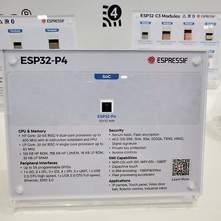
ESP 32 -P4 ESPRESSIF SoC ESP 32 -P4 10x10 mm CPU & Memory HP Core: 32 -bit RISC-V dual-core processor up to 400 MHz with AI instruction extension and FPU LP Core: 32 -bit RISC-V single-core processor up to 40 MHz 128 KB HP ROM, 768 KB HP L2MEM, 16 KB LP ROM, 32 KB LP SRAM Peripheral Interfaces Up to 55 programmable GPIOs 1 x I3 C , 2 x I2C , 3 x SPI, 5 x UART, 1 x USB 2.0 OTG High-speed, 1 x USB 2.0 OTG Full-speed, Ethernet, SDIO 3 .0 Security Secure boot, Flash
in
„EmbeddedWorld 2024 - (weniger) neue Chips, FPGAs und die Raspberry Pi AI Camera“
·
Mikrocontroller und Digitale Elektronik
·
09.04.2024 23:20
·
Fotos
Bild
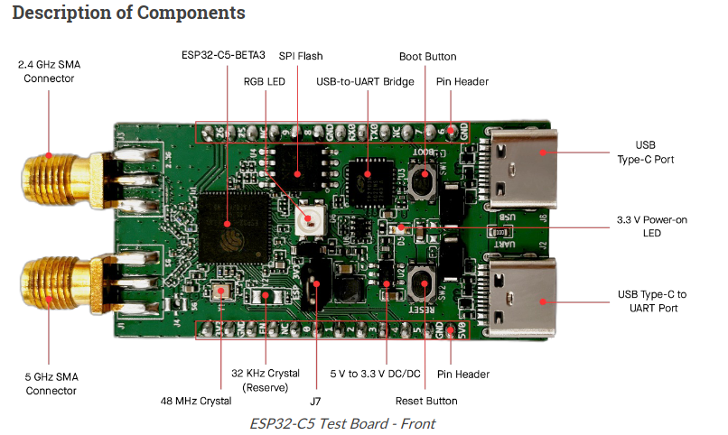
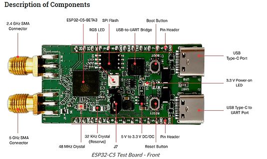
Description of Components
2.4 GHz SMA Connector
ESP 32 -C 5-BETA3
SPI Flash
Boot Button
RGB LED
USB-to-UART Bridge
Pin Header
5 GHz SMA Connector
32 KHz Crystal (Reserve)
5 V to 3 .3 V DC/DC
Pin Header
48 MHz Crystal
J7
Reset Button
USB Type-C Port
3 .3 V Power-on LED
USB Type-C to UART Port
ESP 32 -C 5 Test Board - Front
in
„Devboard zu ESP32-C5 leakt, Orange Pi-Entwicklersymposion und neue RISC/V-Mikrocontroller“
·
Mikrocontroller und Digitale Elektronik
·
31.03.2024 23:06
·
Platinenfotos
PWR_FLAG GND MPU-6050 GND GND GND GND GND GND USB_VBUS B B USB-Port ESP 32 -WROOM-MODULE J2 +3 .3 V USB_C _Receptacle USB_VBUS A4 VBUS C 10 C 11 C 7 22uF 100nF A5 CC1 4.7uF U4 SW1 B5 CC2 R2 R4 2 ESP 32 -WROOM-32 E R5 SW_Push R8 5.1k GND 10k D 10k A7 USB_VBUS 3 D 25 D- USB_D- 5.1k
in
„Prüfung Schaltplan Flight Controller“
·
Mikrocontroller und Digitale Elektronik
·
28.08.2026 19:21
Bild
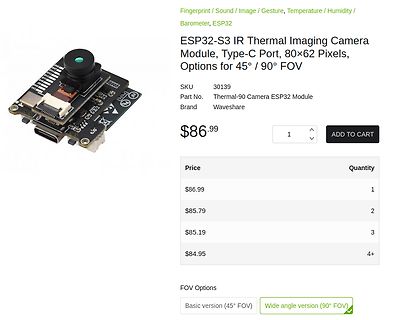
Fingerprint / Sound / Image / Gesture, Temperature / Humidity / Barometer, ESP 32
ESP 32 -S3 IR Thermal Imaging Camera Module, Type-C Port, 80x62 Pixels, Options for 45° / 90° FOV
SKU 30139
Part No. Thermal-90 Camera ESP 32 Module
Brand Waveshare
$86.99
ADD TO CART
Price Quantity
$86.99 1
$85.79 2
$85.19 3
$84.95 4+
FOV Options
Basic version (45° FOV)
Wide angle version (90° FOV)
in
„Microchip-MPU mit 1GHz, Softwareupdates, Thermokamera mit ESP32-S3 uvam“
·
Mikrocontroller und Digitale Elektronik
·
28.02.2025 22:29
·
Screenshots
body { font-family: Arial; text-align: center; padding: 20px; background: #f0f8ff; } h1 { color: #2c 3 e50; font-size: 28px; } .reading { font-size: 64px; color: #007bff; margin: 10px 0; } .time-format { font-size: 38px; color: #7b7bff; margin: 10px 0; } .co2 { font-size: 64px; color: #28a745; font-weight
in
„Micropython Wetterstation“
·
Projekte & Code
·
22.01.2026 16:04
Power 5V ESP 32 GND 9 +3 V3 3 1 D 38 GND 2 GND N GND 37 GND +5V_EXT VCC_12V 3 3 V3 G IO23 36 U6 EN 4 EN IO22 35 LM2596S-5.0 5 SENSOR_VP TXD0 34 RXD C 3 C 4 SENSOR_VN RXD0 TXD L1 1 100nF 22uF 6 IO34 IO21 33 IO21 47uH
in
„ESP32 USB - C Schema“
·
Mikrocontroller und Digitale Elektronik
·
17.01.2024 15:56
Bild
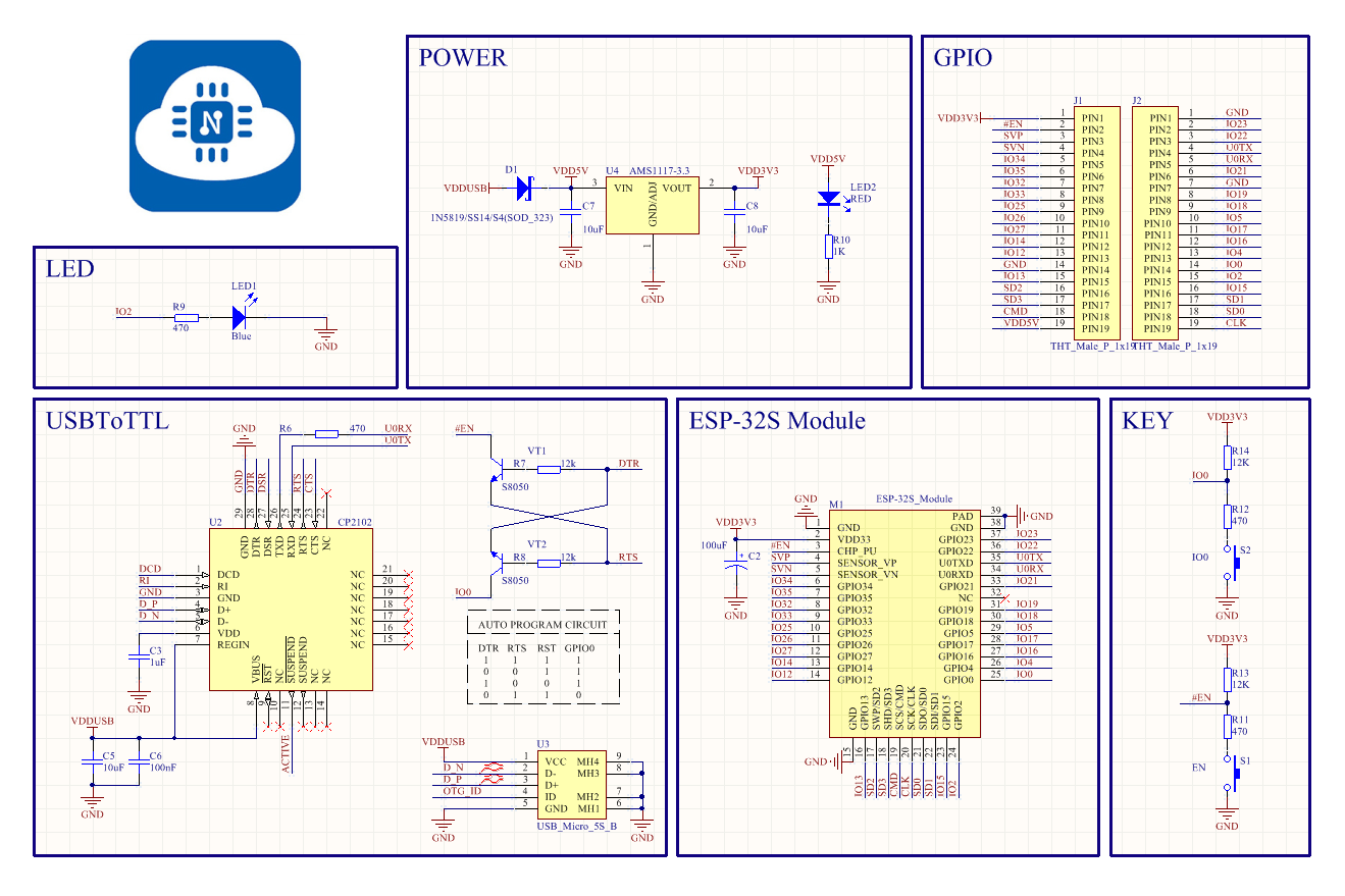
POWER, GPIO, LED, USBToTTL, ESP -32 S Module, KEY, D1, VDD5V, VIN, VOUT, AMS1117-3 .3 , C 7, 10uF, LED2 RED, R10, 1K, GND, U2, CP2102, DTR, RTS, TXD, RXD, DCD, RI, D+, D-, VDD, C 3 , 10uF, VDDUSB, C 5, 100nF, C 6, 100nF, U4, IO0, R7, 470,
in
„D/A Wandler ESP32S3 gibt unterschiedliche Werte“
·
Mikrocontroller und Digitale Elektronik
·
24.06.2026 17:58
·
Schaltpläne
-15 Drawn By: g3 gg0.de 1 2 3 4 5 1 2 3 4 5 T VCC ESP 32 _ WS2812 P 2 1 U4 M L L ESP 32 -WROOM/WROVER T R R I E O D D R 1 2 A R7 N N N 2 1 A 1k O O O S 2 23 16 L L L W S 24O15 I153 W 25O2 G14 VCC5 IO0 26O0 I132 LED5 WDT_WDI
in
„LON Bus Windhager mitlesen/steuern“
·
Softwareentwicklung
·
31.03.2026 22:01
Bild
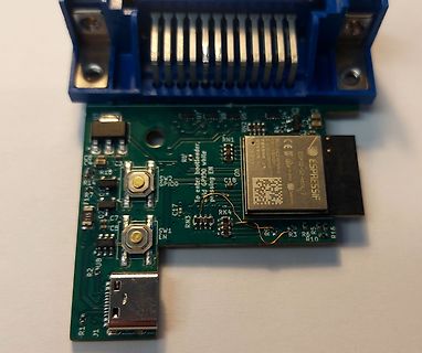
U3 , U7, U6, RN1, ESP 32 -WROOM-32 , ESPRESSIF, ESP 32 -WROOM-32 , SW2 GPIO, GPIO, EN, C 17, RN3 , RK4, SW1 EN, C 1, R2, R3 , R6, R10, R16, J1, R1
in
„Sammelbestellung AR488 kompatibler USB-GPIB Adapter. Interesse?“
·
Mikrocontroller und Digitale Elektronik
·
31.01.2025 15:42
·
Platinenfotos
Bild
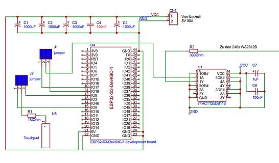
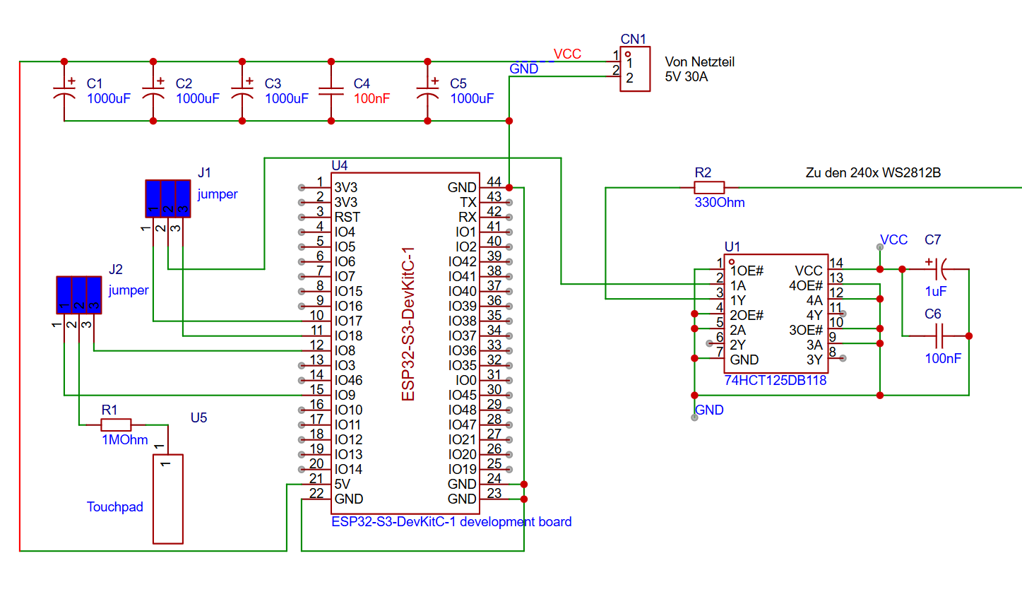
C 1 1000uF C 2 1000uF C 3 1000uF C 4 100nF C 5 1000uF CN1 1 2 VCC GND 5V 30A J1 jumper J2 jumper R2 330Ohm Zu den 240x WS2812B U4 ESP 32 -S3 -DevKitC -1 1 3 V3 2 3 V3 3 RST 4 IO4 5 IO5 6 IO6 7 IO7 8 IO5 9 IO6 10
in
„ESP32 und 240Stück WS2812B“
·
Mikrocontroller und Digitale Elektronik
·
23.12.2025 17:04
·
Schaltpläne
body { font-family: Arial; text-align: center; padding: 20px; background: #f0f8ff; } h1 { color: #2c 3 e50; font-size: 28px; } .reading { font-size: 64px; color: #007bff; margin: 10px 0; } .time-format { font-size: 38px; color: #7b7bff; margin: 10px 0; } .co2 { font-size: 64px; color: #28a745; font-weight
in
„Micropython Wetterstation“
·
Projekte & Code
·
22.01.2026 17:52

 Bild
 Bild

 Bild
 Bild
 Bild
 Bild
 Bild
 Bild
 Bild
 Bild
 Bild
 Bild
 Bild
 Bild
 Bild
 Bild
 Bild
 Bild
 Bild

 Bild
 Bild