-
 Bild
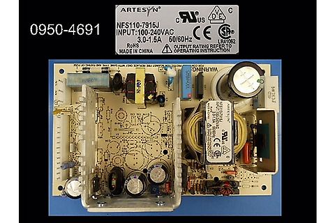
Netzteil Platine mit Transformator und Beschriftung
0950-4691 ARTESYN NFS110-7915J INPUT:100-240VAC 3.0-1.5A 50/60Hz RoHS MADE IN CHINA CE UL CSA LR41062 OUTPUT RATING REFER TO OPERATING INSTRUCTION
in „suche Netzteil aus Agilent Oszillograf MSO-6104“ · Markt · · Platinenfotos
-
PDF
MX29F040C__5V__4Mb__v2.2.pdf
of program and erase operation completion PACKAGE • 32-Pin PLCC • 32-Pin TSOP • All devices are RoHS Compliant P/N:PM1201 REV. 2.2, DEC. 04, 2012 1 M X 2 9 F 0 4 0 C Contents FEATURES.....................................................................................................................
-
PDF
4N32-4n33.pdf
toptically coupled to a silicon planar darlington 110 °C phototransistor detector in a plastic DIP6 RoHS & REACH Compliance package with different lead forming options. MSL class 1 Regulatory Approvals UL - UL1577 VDE - EN60747-5-5(VDE0884-5) CQC - GB4943.1 Applications Low power logic circuits
in „Optokoppler invertieren?“ · Analoge Elektronik und Schaltungstechnik ·
-
PDF
marantz_m-cr611_ver.1_1_-pages.pdf
+ 47uF 104K CV615280S (MPE) (MPE) 50V (2012) 3.3K 25V 1 (2012) 3 OPTION TABLE 2 (105') (2012) (105') D222 AC100V AC220V-240V 1 HS1G R229 2 3 4 C872 D871 (SMA) 1K 330pF HS1M 10 (2012) SW_110V JUMPER NM 2 1KV R228 1 (3216) 3 C222 R223 2.2K
in „Schaltungsaufbau SMPS Marantz M-CR611“ · Analoge Elektronik und Schaltungstechnik ·
-
PDF
NCP1605-D.PDF
55°C to +125°C 51 − 69 Pin 7 Source Current: mA RAMP − 1.75 V @ V Pin4 1.75 V 156 182 214 RAMP − 2.50 V @ V Pin4 2.50 V 313 370 428 Vcl_ff Pin 7 Clamp Voltage @Pin4= VPin2= 2 V and Pin6= 0 V − 5 − V V CLCRM Pin 7 Clamp Voltage @Pin4= 0 V, Pin2= 2 V and Pin6 1 V 0.9 1 1.1 V Product parametric performance
in „Hilfe bei der Reparatur eines Schaltnetzteiles erbeten“ · Analoge Elektronik und Schaltungstechnik ·
-
PDF
TPS2113A.pdf
IN2)3.3 V V I(IN2)3.3 V I I = 0 A I(IN1) O(OUT) 60 IO(OUT)= 0 A m I = 5.5 V m - I(IN1) - n 0.8 t e e 50 r r C C l 0.6 y 40 p p u u S S 30 - 0.4 - x x II I I 20 0.2 10 II(IN2)3.3 V II(IN2) 0 0 -50 0 50 100 150 -50 0 50 100 150 TJ- Junction Temperature - C° TJ- Junction Temperature - C° Figure 12. Figure
in „Speisung umschalten“ · Analoge Elektronik und Schaltungstechnik ·
-
PDF
TPS2120.pdf
MIN No Spikes IOUT IIN1 0 Time VOUT,MIN VIN1+ VRCB- (SWx SR OUT where SR OUT= OUT/COUT V = 4.25 V + 50 mV - (5µs x 30mV/µs) = 4.15 V OUT,MIN VOUT,MIN 4.25 V + 50 mV - (5µs x 1A/10µF) = 3.8 V V OUT,MIN 4.25 V + 50 mV (5µs x 1A/100µF) = 4.25 V Figure 9-9. Fast Switchover from Higher to Lower Voltage 9.3.8
in „Speisung umschalten“ · Analoge Elektronik und Schaltungstechnik ·
-
PDF
TPS2115A.pdf
vs LOAD CAPACITANCE 5 VI= 5 V 4.5 V - 4 o r 3.5 D g l 3 R L 10 W o t 2.5 u u 2 O -) T 1.5 U ( 1 RL= 50 W VO 0.5 0 0.1 1 10 100 C L Load Capacitance -mF VI TPS2115APW 1 8 0.1 mF NC STAT IN1 f = 28 Hz 2 D0 OUT 7 50% Duty Cycle 3 6 D1 IN2 4 ILIM GND 5 400 W 50 W 10 W 0.1 mF 0.1 mF 1 mF 10 mF 47 mF 100 mF
in „Speisung umschalten“ · Analoge Elektronik und Schaltungstechnik ·
-
PDF
rgs50tsx2d-e.pdf
Marking RGS50TSX2D lAbsolute Maximum Ratings (at T = 25°C unless otherwise specified) C Parameter Symbol Value Unit Collector - Emitter Voltage VCES 1200 V Gate - Emitter Voltage VGES ±30 V TC= 25°C IC 50 A Collector
in „Induktions Doppelfeld (stand alone) - eine Seite hinüber.“ · Analoge Elektronik und Schaltungstechnik ·
-
PDF
DB_SunPower_400W_MAXEON_3.pdf
Punkte für die LEED- und ökologischen Bauweise BREEAM-Zertifizierung beitragen. 14 EHS-Konformität RoHS, OHSAS 18001:2007, bleifrei, Recycling, REACH SVHC- 163 1 Basierend auf den Angaben in Datenblättern auf den Websites der 20 führenden Hersteller laut IHS (Stand:Januar 2020). 2 Jordan, et. al.:„Robust
in „welches sind die besten microinverter für solarpanele mit einer leistung bis 200-220 watt“ · Haus & Smart Home ·
-
 Bild
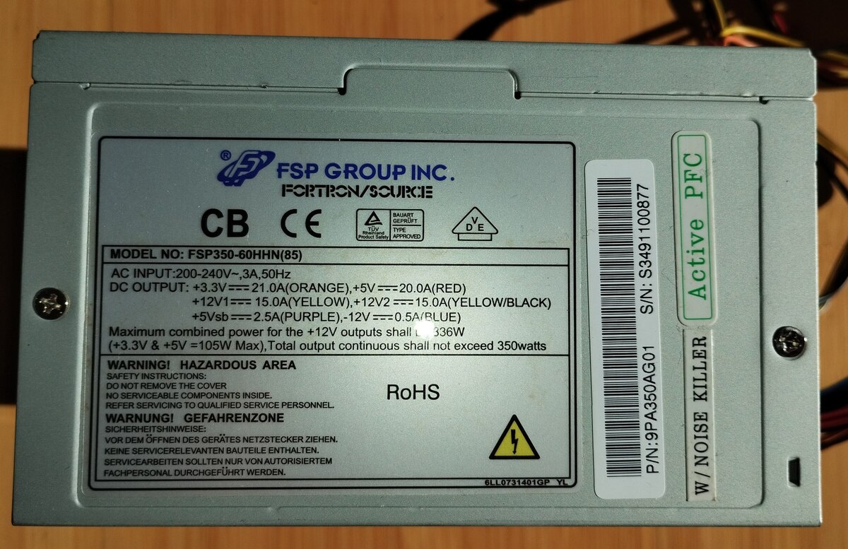
Typenschild eines FSP Netzteils
FSP GROUP INC. FORTRON/SOURCE CB CE MODEL NO: FSP350-60HHN(85) AC INPUT: 200-240V~, 3A, 50Hz DC OUTPUT: +3.3V==21.0A(ORANGE), +5V==20.0A(RED) +12V1==15.0A(YELLOW), +12V2==15.0A(YELLOW/BLACK) -12V==0.5A(BLUE) Maximum combined power for the +12V outputs shall be 336W (+3.3V & +5V=105W Max),
in „[V] 7390, FSP 350W ATX-Netzteil“ · Markt · · Fotos
-
 Bild
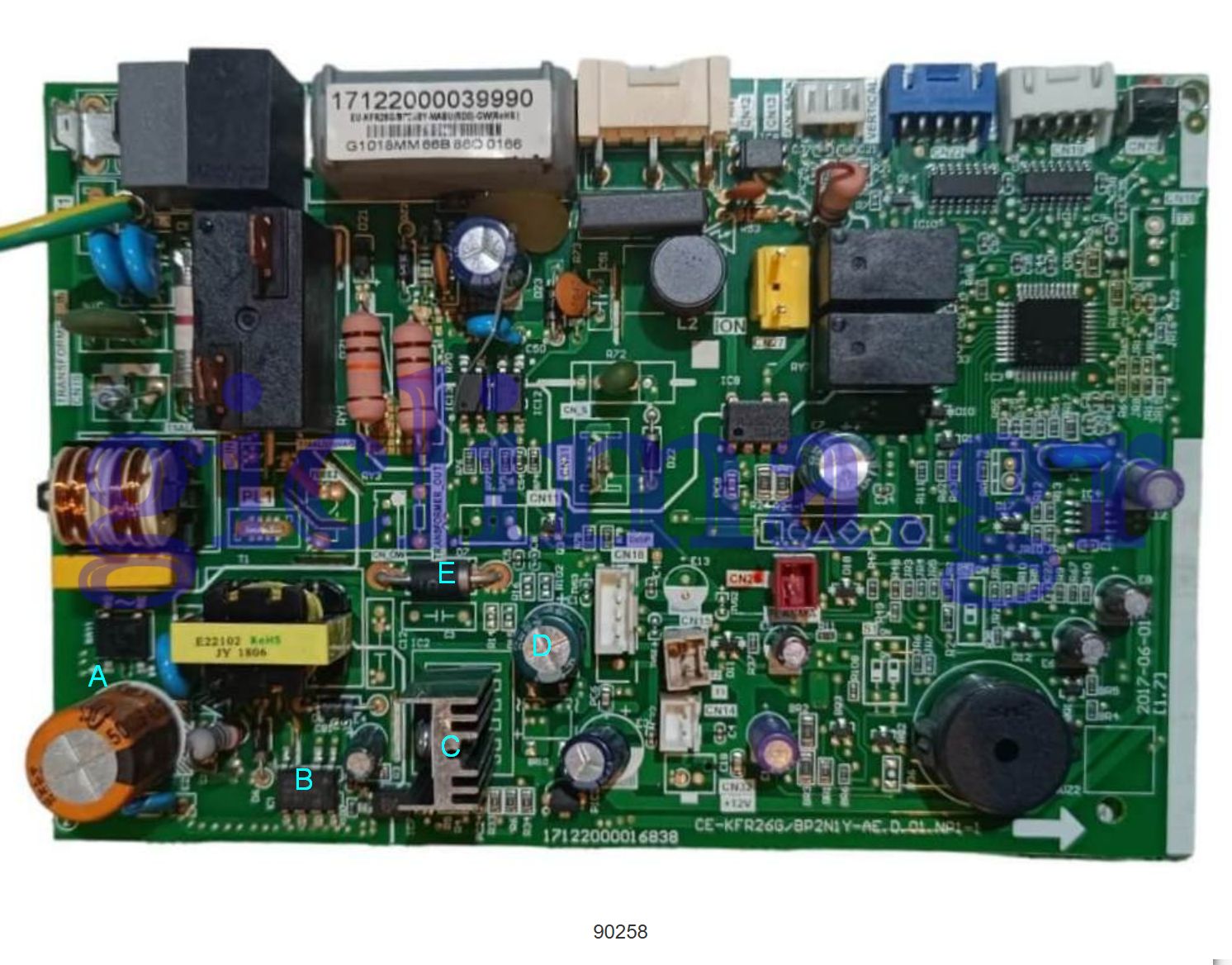
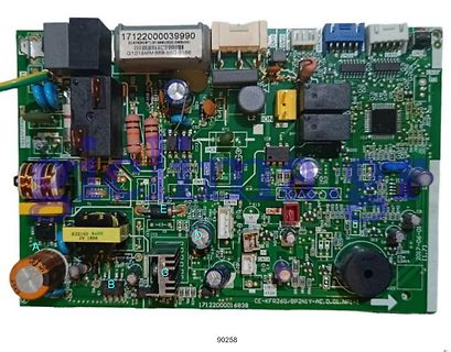
Foto einer bestückten Leiterplatte mit Bauteilmarkierungen
17122000039990 G1018MM6B B60 0166 E23102 K4HS JV 1866 L2 ION CN1 CN2 CN3 CN10 CN16 CN17 CN18 CN19 CN20 CN21 CN22 CN23 CN24 CN25 CN26 CN27 CN28 CN29 CN30 CN31 CN32 CN33 CN34 CN35 CN36 CN37 CN38 CN39 CN40 CN41 CN42 CN43 CN44 CN45 CN46 CN47 CN48 CN49 CN50 CN51 CN52 CN53 CN54 CN55 CN56 CN57 CN58 CN59 CN60 CN61 CN62 CN63 CN64 CN65 CN66 CN67 CN68 CN69 CN70 CN71 CN72 CN73 CN74 CN75 CN76 CN77 CN78 CN79 CN80 CN81 CN82 CN83 CN84 CN85 CN86 CN87 CN88 CN89 CN90
in „Reparatur Split-Klima - SNT - Diode SR315“ · Analoge Elektronik und Schaltungstechnik · · Platinenfotos
-
PDF
ach-wtb.pdf
rating: 1 to 3 circuits/ 2 A AC/DC (AWG #28) 3 4, 5 circuits/ 1.5 A AC/DC (AWG #28) • Voltage rating: 50 V AC, DC • Temperature range: -25℃ to +85℃ (including temperature rise in applying electrical current) • Contact resistance:Initial value/ 10 mΩ max. After environmental tests/ 20 mΩ max. • Insulation
in „4 pol. Lüfterstecker SMT auf PCB“ · PC Hard- und Software ·
-
PDF
LM78XX.pdf
4.75 5.25 V OUT D Dropout Voltage VD T J25°C 2.0 V Load Regulation ΔV OUT T J25°C,I OUT=5mA - 1.0A 50 mV T J=25°C,IOUT=0.25A - 0.75A 25 mV Line regulation ΔV OUT V INV ~ 25V, T =J5°C 50 mV V IN=7.5V ~ 20V, TJ=25°C, IOUT=1.0A 50 mV Quiescent Current IQ T J25°C, I OUT≦1.0A 8.0 mA V IN.5V ~ 20V 1.0 mA Quiescent
in „2 Spannungen mit 1 Labornetzteil“ · Analoge Elektronik und Schaltungstechnik ·
-
PDF
AP3031.pdf
www.diodes.com/quality/product-definitions/ Notes: 1. No purposely added lead. Fully EU Directive 2002/95/EC (RoHS), 2011/65/EU (RoHS 2) & 2015/863/EU (RoHS 3) compliant. 2. See https://www.diodes.com/quality/lead-free/ for more information about Diodes Incorporated’s definitions of Halogen- and Antimony-free, "Green
in „Verständnisfrage Datenblatt AP3031 PMIC“ · Mikrocontroller und Digitale Elektronik ·
-
PDF
Schematic__1_.pdf
BC_EN3 USBDP_DN4/PRT_DIS_P4 9 USB4_P 20 PRTPWR4/BC_EN4 USBDM_DN1/PRT_DIS_M1 1 USB1_N GND 25 3 USB2_N HS_IND/CFG_SEL1 USBDM_DN2/PRT_DIS_M2 6 USB3_N 24 USBDM_DN3/PRT_DIS_M3 8 USB4_N 22 SCL/CFG_SEL0/SMBCLK USBDM_DN4/PRT_DIS_M4 USB2 SDA/SMBDATA/NON_REM1 28 A4/B9 VBUS 34 SUSP_IND/LOCAL_PWR/NON_REM0 VBUS B4/
in „Hilfe benötigt! Pi Compute Module 4 Carrier Board ohne Funktion!“ · Mikrocontroller und Digitale Elektronik ·
-
 Bild
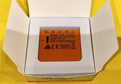
Shelly i3 Modul in Verpackung
I3 I2 I1 N L Shelly i3 ~24-60V, ~110-240V SW inputs, up to ~60V or ~240V 50/60Hz, -20...+40°C Shelly® by Allterco Robotics Ltd. ACE RoHS COMPLIANT
in „[V] Shelly Aktoren, Vocolink Leuchtmittel # (Homeautomation)“ · Markt · · Fotos
-
 Bild
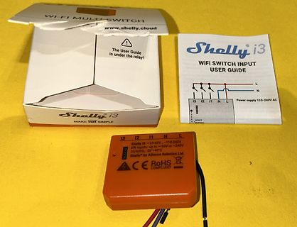
Shelly i3 WiFi Switch mit Verpackung und Anleitung
IoT SIMPLE Powered by Allterco Robotics Shelly i3 ~24-60V, ~110-240V SW inputs: up to ~60V or ~240V 50/60Hz, -20...+40°C Shelly by Allterco Robotics Ltd. ACE RoHS COMPLIANT
in „[V] Shelly Aktoren, Vocolink Leuchtmittel # (Homeautomation)“ · Markt · · Fotos
-
 Bild
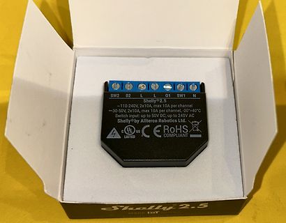
Shelly 2.5 Smart Switch in Verpackung
Shelly 2.5 SW2 02 L L 01 SW1 N ~110-240V, 2x10A, max 10A per channel -30-50V, 2x10A, max 10A per channel, -20-+40°C Switch input: up to 50V DC; up to 240V AC Shelly® by Allterco Robotics Ltd. UL LISTED CE RoHS COMPLIANT Shelly 2.5 MAKE IoT
in „[V] Shelly Aktoren, Vocolink Leuchtmittel # (Homeautomation)“ · Markt · · Fotos
-
PDF
Tyco_MQS__ENG_CS_1307999-3_.pdf
FLK FLR and Finish Strip Package (mm ) (mm) (mm) Form Quantity Applicator Hand Tool Die Set 0.35–0.50 – 1.1–1.6 tin plated 1241603-1 8,500 2151035 539635-1 539693-2 0.75–1.50 – 1.7–2.4 tin plated 1241605-1 8,500 2151575 Clean Body Insulation Diameter Wire Size Part Numbers Range Material Strip Package (mm 2) FLK FLR and Finish Form Quantity Applicator Hand Tool Die Set (mm) (mm) 0.35–0.50 – 1.1–1.6 tin plated 1452158-1 12,000 2151252 539635-1 539692-2 0.75–1.50 – 1.7–2.4 tin plated 1241608-1 8,500 2151066 1-14 All specifications subject to change. Consult TE Connectivity for latest specifications
-
PDF
Ultra_Excellent_ab_11-2007.pdf
Anschlüsse A3 und 4 Räume, IP 20 überprüfen Funkfernsteuerung 433 MHz AM Handsenderreichweite * 15 - 50 m Antrieb läuft Schlitten nicht eingeklinkt / fehlerhaft Zahnriemen nicht gespannt / Handsender-Batterie CR 2032 (3V) Torschwelle vereist Laufgeschwindigkeit ~ AUF >100 mm/s Antrieb schaltet Tor auf
in „Belegung Garagentorantrieb Normstahl“ · Haus & Smart Home ·
-
PDF
REN_r01ds0145ej0102_v850e2fe4l_DST_20140421.pdf
Chapter 8 Memory specification . . . . . . . . . . . . . . . . . . . . . . . . . . . . . . . . . . 50 8.1 Code flash specification. . . . . . . . . . . . . . . . . . . . . . . . . . . . . . . . . . . . . . . . . . . . . . 50 8.2 Data flash specification . . . . . . . . . . . . . . . . . . . . . . . . . . . . . . . . . . . . . . . . . . . . . . 50 8.3 Serial write operation specification. . . . . . . . . . . . . . . . . . . . . . . . . . . . . . . . . . . . . 50 Chapter 9 Pinning and package specification . . . . . . . . . . . . . . . . . . 51
in „Renesas V850 (3572 (A2) FE4-L) auslesen / programmieren?“ · Mikrocontroller und Digitale Elektronik ·
-
PDF
Danfoss_Katalog_BLDC_Compressors.pdf
(P-Housing) (T-Housing) BD35F /-HD /-B 9.6 – 31.5 BD350GH 24V 19 – 31.5 BD35F AC/DC 85 – 265V AC, 50/60 Hz z BD350GH 12/24V 9.6 – 31.5 BD35F Solar option 1 9.6 - 30 BD350GH 48V 32 - 60 option 2 20 - 45 BD220CL 9.6 - 17 BD50F 9.6 – 31.5 BD150F 160 – 254V AC 50/60 Hz BD50F AC/DC 85 – 265V AC, 50/60 Hz
in „12V Kompressor Kühlbox - Steuerung defekt - eigenes Thermostat verwenden“ · Haus & Smart Home ·
-
PDF
SCT-013-015.pdf
transformer Model: SCT-013 Rated input current:5A/100A Characteristics:Openning size: 13mm*13mm, RoHS Non-linerity±3%(10%—120% of rated input current) 1m leading wire, standard Φ3.5 three core plug output. Current output type and voltage output type (voltage output type built-in sampling resistor) Purpose
in „SCT013 15A/1V“ · Analoge Elektronik und Schaltungstechnik ·
-
PDF
Fujitsu_Esprimo_p756-e90-de.pdf
ElektrischeAnschlusswerte Leistungseffizienz–Hinweis EnergieeffizienzdesNetzteils(bei230 VundeinerAuslastungvon10%/20 %/50 %/100 %):84 %/90%/92 %/ 91 % Nennspannungsbereich 100V-240 V Nennfrequenzbereich 50 Hz-60 Hz Betriebsspannungsbereich 90 V-264 V Betriebsnetzfrequenzbereich 47 -63 Hz Max.Netzteil-Ausgangsleistung
in „Speichererweiterung Rechner !“ · PC Hard- und Software ·
-
PDF
NTS4409N-D.pdf
mW @ 2.7 V • AEC−Q101 Qualified and PPAP Capable − NVS4409N • These Devices are Pb−Free and are RoHS Compliant SC−70 (3−Leads) Applications • Boost and Buck Converter Gate 1 • Load Switch • Battery Protection 3 Drain MAXIMUM RATINGS (TJ= 25°C unless otherwise noted) Source 2 Rating Symbol Value Unit
in „SMD Identifizieren“ · Analoge Elektronik und Schaltungstechnik ·
-
PDF
WM8070-A01_-_Schaltungsbeschreibung_-_2021_DE.pdf
≈0,35-1A R1=Ri≈100K R1=80R Ri>1M I≈0,35-1A R1=Ri≈100K R1=80R Ri>1M I≈0,35-1A R1=Ri≈100K U≈5mV-2V R≈50-200 U≈4V-50V U≈5mV-2V R≈50-200 U≈4V-50V U≈5mV-2V R≈50-200 U≈4V-50V U≈5mV-2V R≈50-200 U≈4V-50V U≈5mV-2V R≈50-200 U≈4V-50V 125.00 I≈1-350mA . R≈200-100K I≈1-350mA . R≈200-100K I≈1-350mA . R≈200-100K I≈
in „WOMA HAMEG WM8070-A01 Adaptermodul für HAMEG HM8070“ · Projekte & Code ·
-
Thread
Tonsignal in Echtzeit verändern
Wenn's wirklich live sein soll, ist das ein extrem ambitioniertes Unterfangen. Bei 50 dB Dämpfung muss man schon Nebenkanäle wie Knochenleitung mit berücksichtigen.
Projekt. Ich konnte auch noch nicht finden, ob ich bei beliebigen Frequenzen eine Dämpfung von etwa 50 dB einstellen kann.
Digitale Signalverarbeitung / DSP / Machine Learning ·Thomas · ·44 Antworten
-
PDF
WM8070-A01_-_Schaltungsbeschreibung_-_2021_DE.pdf
≈0,35-1A R1=Ri≈100K R1=80R Ri>1M I≈0,35-1A R1=Ri≈100K R1=80R Ri>1M I≈0,35-1A R1=Ri≈100K U≈5mV-2V R≈50-200 U≈4V-50V U≈5mV-2V R≈50-200 U≈4V-50V U≈5mV-2V R≈50-200 U≈4V-50V U≈5mV-2V R≈50-200 U≈4V-50V U≈5mV-2V R≈50-200 U≈4V-50V 125.00 I≈1-350mA . R≈200-100K I≈1-350mA . R≈200-100K I≈1-350mA . R≈200-100K I≈
-
PDF
TCST2300.pdf
T amb = 25 °C, unless otherwise specified I F F F + 5 V 0 tp 0 I adjusted by I C t C F 100 % R G = 50 Ω 90 % p = 20 T tp= 1 ms Channel I 10 % Oscilloscope 0 R ≥ 1 MΩ r Channel II L td ts tf t C L≤ 20 pF t off 50 Ω 100 Ω on 20688 tp Pulse duration ts Storage time td Delay time tf Fall time tr Rise time
in „Datenlogger Pendeluhr“ · Mikrocontroller und Digitale Elektronik ·
-
PDF
Widerstaende.pdf
joint for 0000 = jumper MBA/SMA 0204 D = Ni wire for MBA/SMA 0204 Product Description: MBB/SMA 0207-50 1 % CT 1K0 MBB/SMA 0207 - 50 1 % CT 1K0 TYPE/SIZE TCR TOLERANCE VARIANT PACKAGING RESISTANCE MBA/SMA 0204 ± 25 ppm/K ± 0.5 % RB CT 1K0 = 1 kΩ MBB/SMA 0207 ± 50 ppm/K ± 1.0 % UB C1 51R1 = 51.1 Ω MBE/SMA
in „Widerstand identifizieren“ · Analoge Elektronik und Schaltungstechnik ·
-
PDF
str-x6759n_ds_en.pdf
Current IDmax T A –20°C to 125°C 22 A Single Pulse Avalanche Energy EAS Single pulse, DD = 30 V, L = 50 mH, Lpeak 4.4 A 500 mJ Input Voltage for Controller (MIC) VCC 35 V SS/OLP Terminal Voltage V SSOLP –0.5 to 6.0 V FB Terminal Inflow Current IFB 10 mA FB Terminal Voltage VFB IFBwithin the limits FB I
in „Reparatur Netzteil PHILIPS HTS 8140/12“ · Analoge Elektronik und Schaltungstechnik ·
-
PDF
TCST1202.pdf
time R = 100 Ω (see figure 2) toff 8 μs L IF 0 tp t + 5 V C IF IF 100 % 0 C adjusted byFI 90 % R = 50 Ω G p T = 20 10 % tp= 1 ms 0 r Channel I Oscilloscope t td ts f RL ≥ 1 MΩ ton toff Channel II C ≤ 20 pF p Pulse duration s Storage time 50 Ω 100 Ω L d Delay time t Fall time r Rise time off= s +ft) Turn-off
in „Datenlogger Pendeluhr“ · Mikrocontroller und Digitale Elektronik ·
-
PDF
BMP581.pdf
220.00 220.00 200.00 180.00 140.00 100.00 70.00 40.00 _ 8 140.00 140.00 130.00 120.00 100.00 80.00 50.00 35.00 S O 16 80.00 80.00 80.00 70.00 70.00 50.00 45.00 30.00 32 45.00 45.00 40.00 40.00 40.00 35.00 30.00 20.00 64 20.00 20.00 20.00 20.00 20.00 20.00 15.00 15.00 128 10.00 10.00 10.00 10.00 10.00
in „Datenlogger Pendeluhr“ · Mikrocontroller und Digitale Elektronik ·
-
PDF
BMA456.pdf
.................................................................................................. 50 Register (0x17) DATA_13.................................................................................................. 50 Register (0x18) SENSORTIME_0..............................................
in „Datenlogger Pendeluhr“ · Mikrocontroller und Digitale Elektronik ·
-
 Bild
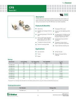
Datenblatt für CF8 58V Sicherungen
CF8 799 Series fuse holders separately. Features & Benefits Fast-acting Available with ratings of 50 A to 300 A Interrupting ratings of 2 kA at 58 VDC 50 A to 100 A fuses operate at up to 105 °C; 125 A to 300 A fuses operate at up to 125 °C Tin-plated zinc alloy terminals Ceramic insulating bodies Transparent
in „Wie heißt diese Bauart von Schmelzsicherung?“ · Analoge Elektronik und Schaltungstechnik · · Screenshots
-
PDF
SD211SeriesDSRevA10.pdf
Call-Out Standard Part Call-Out (Custom Parts Include SEL + 4 Digit Numeric Code) SD211DE TO-72 4L RoHS SD211DE TO-72 4L RoHS SELXXX SD213DE TO-72 4L RoHS SD213DE TO-72 4L RoHS SELXXX SD215DE TO-72 4L RoHS SD215DE TO-72 4L RoHS SELXXX SST211 SOT-143 4L RoHS SST211 SOT-143 4L RoHS SELXXX SST213 SOT-143 4L RoHS SST213 SOT-143 4L RoHS SELXXX SST215 SOT-143 4L RoHS SST215 SOT-143 4L RoHS SELXXX Doc 20114 09/14/2022 Rev# A11 ECN# SD-SST211www.linearsystems.com Page 4 of 4
in „Schaltung mit 2 N-Kanal Mosfet“ · Analoge Elektronik und Schaltungstechnik ·
-
PDF
HLMP-2885.pdf
Red) Deep Red) IV Bin Category Min. Max. IV Bin Category Min. Max. a 3.00 5.60 a 10.80 22.00 A A B 4.50 8.20 B 18.00 27.10 C 6.80 12.10 C 22.00 40.80 b 10.10 18.50 b 33.30 61.10 D D E 15.30 27.80 E 50.00 91.80 F 22.80 45.50 F 75.10 150.00 G 36.90 73.80 G 121.70 243.40 H 59.70 116.90 H 197.10 385.40 I 95.60
-
PDF
PCF8574.pdf
SCL = VCC All I/Os unloaded 80 All I/Os unloaded 100 ) VCC = 5 V )70 ( m VCC= 5 V t 80 t60 e e u 60 r50 C C l l40 VCC= 2.5 V p 40 p30 S u VCC = 3.3 V VCC = 3.3 V S20 20 VCC = 2.5 V 10 0 0 −50 −25 0 25 50 75 100 125 −50 −25 0 25 50 75 100 125 Temperature (°C) Temperature (°C) Figure 1. Supply Current vs
-
PDF
DLG7137.pdf
x 7 Dot Matrix Intelligent Display® Devices with Memory/Decoder/Driver Lead (Pb) Free Product - RoHS Compliant SUPER-RED: DLO4135, DLO7135 GREEN: DLG4137, DLG7137 DLO4135 / DLG4137 DLO7135 / DLG7137 FEATURES DESCRIPTION • 5 x 7 Dot Matrix Characters The DLX413X/DLX713X are single digit 5 x 7 dot DLO4135
-
PDF
I2C-bus_specification_2014.pdf
outputs which can stretch the serial clock signal SCL or SCLH. Fig 36. Bus system with transfer at Hs-mode and F/S-mode speeds Table 8. Communication bit rates in a mixed-speed bus system Transfer between Serial bus system configuration Hs + Fast + Hs + Fast Hs + Standard Fast + Standard Standard Hs
in „Wodtke HP-S5 HP Er3 EEPROM Schreib-/Lesefehler“ · Haus & Smart Home ·
-
PDF
24fc256.pdf
the • Data Retention >200 years • Factory Programming Available 24AA256/24LC256/24FC256 devices. • RoHS Compliant • Temperature Ranges: - Industrial (I): -40C to +85C - Extended (E): -40C to +125C • Automotive AEC-Q100 Qualified Package Types (1) CSP DFN/TDFN MSOP/PDIP SOIC/SOIJ/TSSOP SOT-23 VCC A1
in „Wodtke HP-S5 HP Er3 EEPROM Schreib-/Lesefehler“ · Haus & Smart Home ·
-
PDF
Amplifier_LM3886.pdf
Samples may or may not be available. OBSOLETE: TI has discontinued the production of the device. (2) RoHS: TI defines "RoHS" to mean semiconductor products that are compliant with the current EU RoHS requirements for all 10 RoHS substances, including the requirement that RoHS substance do not exceed 0.1% by weight in homogeneous materials. Where designed to be soldered at high temperatures, "RoHS" products are suitable for use in specified lead-free processes. TI may reference these types of products as "Pb-Free". RoHS Exempt: TI defines "RoHS Exempt" to mean products that contain lead but are
in „LM3886 LTspice Error“ · Analoge Elektronik und Schaltungstechnik ·
-
PDF
VND830SP.pdf
V CC pin (part 1) ISO T/R Test levels 7637/1 test pulse I II III IV Delays and impedance 1 -25 V -50 V -75 V -100 V 2 ms, 10 Ω 2 +25 V +50 V +75 V +100 V 0.2 ms, 10 Ω 3a -25 V -50 V -100 V -150 V 0.1 µs, 50 Ω 3b +25 V +50 V +75 V +100 V 0.1 µs, 50 Ω 4 -4 V -5 V -6 V -7 V 100 ms, 0.01 Ω 5 +26.5 V +46.5
in „[V] Highside-Schalter“ · Markt ·
-
PDF
VN920SP.pdf
V CC pin (part 1) ISO T/R Test levels 7637/1 test pulse I II III IV Delays and impedance 1 - 25V - 50 V - 75 V - 100 V 2 ms, 10 Ω 2 + 25 V + 50 V + 75V + 100V 0.2 ms, 10 Ω 3a - 25 V - 50 V - 100 V - 150 V 0.1 µs, 50 Ω 3b + 25 V + 50 V + 75 V + 100 V 0.1 µs, 50 Ω 4 - 4 V - 5 V - 6 V - 7 V 100 ms, 0.01
in „[V] Highside-Schalter“ · Markt ·
-
PDF
mkp_b32714h_718h.pdf
640 V DC R,85 °C op,100 °C 45.0 30.0x45.0x57.5 20.3 B32718H8456+000 19.0 16.5 5.3 14.5 2.6 25.5 280 50.0 30.0x45.0x57.5 20.3 B32718H8506K000 19.6 17.0 5.0 14.5 2.7 25.8 280 55.0 35.0x50.0x57.5 20.3 B32718H8556+000 22.4 19.5 4.4 16.0 2.7 25.9 108 60.0 35.0x50.0x57.5 20.3 B32718H8606+000 23.5 20.4 4.0 16.5
in „[V] MKP-Kondensatoren 4 µF und 100 nF mit 1 kV Spannungsfestigkeit“ · Markt ·
-
PDF
Flusswandler.pdf
742792093 VCC C33 100n FB1 4 U5A 742792093 D12 CU8965-AL R46 3 GNDPWR 1N4148W 10R V C23 C25 H D17 HS2 TP4 ES1J Heatsink 10u 100n U8 PWM TR3 R44 2 TP1 UC3845D8 U9 P0544NLT 10R B FB 7 UCC27425QDRQ1 C34 3 1 Q6 B FB GNDPWR GNDPWR Comp 1 VCC R36 1 6 R6035VNXC7G COMP 1k ENBA VDD 10u D14 Vref 8 VREF OUT 6
in „Kurzschlussinduktivität != Streuinduktivität?“ · Analoge Elektronik und Schaltungstechnik ·
-
PDF
DS_FT2232H.pdf
requirement for USB driver development in Available in compact Pb-free 56 Pin VQFN most cases. packages (RoHS compliant) Adjustable receive buffer timeout. +3.3V single supply operating voltage range. Option for transmit and receive LED drive ESD protection for FT2232H IO’s: signals on each channel.
-
PDF
efm8ub2-datasheet-1666225.pdf
Low Period requirements of their respective specifi- cations. 3.SMBus has a maximum requirement of 50 µs for Clock High Period. Operating frequencies lower than 40 kHz will be longer than 50 µs. I2C can support periods longer than 50 µs. silabs.com | Smart. Connected. Energy-friendly. Rev. 1.3 | 21 EFM8UB2
in „[V] 20St. SILABS 8051 USB-EFM8UB20F64G-B - QFP32 (15€)“ · Markt ·
-
PDF
HCPL-4701-360E.pdf
rmsfor 1 minute per UL1577 and are approved under CAN/CSA-C22.2 No. 62368-1. Option Tape UL5000 RoHS Non-RoHS Surface Gull and Vrms/1Minute IEC/EN/DIN Part Number Compliant Compliant Package Mount Wing Reel Rating EN60747-5-5 Quantity HCPL-4701 -000E No option 300-mil DIP- 50 per tube HCPL-4731 8 -300E -300 X X 50 per tube -500E -500 X X X 1000 per reel -020E -020 X 50 per tube -320E -320 X X X 50 per tube -520E -520 X X X X 1000 per reel -060E -060 X 50 per tube -360E -360 X X X 50 per tube -560E -560 X X X X
in „DI mit geringer Stromaufnahme und hoher Spannungsfestigkeit“ · Mikrocontroller und Digitale Elektronik ·