Bauteile-Liste...) einfügen. Anschließend bitte noch das Simulation Command umändern in .dc V1 550mV 750mV 10mV Damit wird nur der Spannungsbereich von 550mV bis 750mV dargestellt und in Schritten von 10mV simuliert. Das ist für eine Siliziumdiode genau richtig. 75 10.3. NPN-Transistor Da gibt es in
DF !er P OW P OW uN uyN tbStrombelastbarkeit bei fester Verlegung in und an Gebäuden tob lk li ww C m w C m wdoc uac Dauerbetrieb w.doc ac.c u-t u-r Umgebungstemperatur 25 °C Für Kupferleiter mit PVC-Isolierung. Betriebstemperatur der PVC-Isolierung 70 °C. Zuordnung des Bemessungsstromes I von Überstrom-Schutzeinrichtungen
Solomon Systech 4 BLOCK DIAGRAM Figure 4-1 SSD1306 Block Diagram RES# CS# D/C# E (RD#) R/W#(WR#) t ) D M r BBS1 y A l o r COM62 c l R r m v |OM60 BS0 C r i D n m r | M t D ( C C D COM2 D6 I i y COM0 D5 p A p D4 r R i D3 G D t SEG0 D1 e e SEG1 D0 m i | e D SEG126 S SEG127 V DD COM1 VSS o r COM3 VLSS m v
and 250 MHz. Inputs B0–B1 control the bandwidth of Preamp 4. See Table 1–2. H Six gain settings of 1 mV, 2 mV, 5 mV, 10 mV, 20 mV, and 50 mV per division (see Table 1–3). Inputs G0–G2 control the gain of Preamp 4. H High-frequency adjust inputs. H A variable gain control input which linearly adjusts the
Nein, entscheidend ist der Impulsstrom, der beim Herstellen einer Verbindung fließt, der kann x00 mA für einige µs betragen. Der Y-Kondensator stellt einen kapazitiven Spannungsteiler dar. Wenn im Augenblick der Verbindungsherstellung die Netzspannung im Scheitel liegt (325V), sind beide Cs auf 162,5V
Andreas M. schrieb im Beitrag #7619780: > Beschreibe mal wo die eingebaut sein sollen! [code] L O----------+ | Y Kondensator === | GND Sekundär +
0 T156 R182 R R 0 1 1 1 R135 SB647 10 C FAN 1 4 0 0 8 V 1 U L OUT P R 2 1 C 1.8K 1 . 1 0 R183 5 P T162 T 9 5 C 1 10 8 K B 5 C102 K 8 9 C116 6 6 6 6 6 6 6 3 R 4 1 / 1 2 T163 1 1 5 1 0 1 0 7 3 7 4 9 . 7 0 R R R R R R R 0 C 0 C U D136 3 3 2 330P 1 7 W R 1 R 1 0 2 0 R 3 1 2 1 W R 1 7 1 0 T164 4 1 1 1 5 D
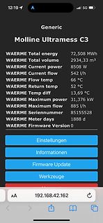
Generic
Molline Ultramess C3
WAERME Total energy 72,508 MWh
WAERME Total volume 2934,33 m³
WAERME Current power 8508 W
WAERME Current flow 542 l/h
WAERME Flow temp 66 °C
WAERME Return temp 52 °C
WAERME Temp diff 13,69 °C
WAERME Maximum power 31,376 kW
WAERME Maximum flow 885 l/h
WAERME Seriennummer
D/A) BBPlG TenneT X X P69 M105 Emden_Ost - Conneforde - Emden/Ost - BBPlG TenneT X X Conneforde P72 M351 Lübeck - Göhl BBPlG TenneT X X P72 M49 Lübeck - Siems BBPlG TenneT X X P72 M50 Segeberg - Lübeck BBPlG TenneT X X P84 M367
Datenblatt zu dem RAM µPD444: https://www.datasheetarchive.com/datasheet?id=1073198b21e4073cc0c21c3b93d95c162a3ed6&type=M&term=upd4441 Hat die Batterie noch genug Spannung? Das ist zum Glück kein NVRAM. So eines habe ich mal aufgefräst und eine externe Batterie angelötet. Das war in einer SMD-Lötstation
Andreas M. schrieb im Beitrag #7614681: > Z80 hat Es ist leider kein Z80.
Host USB non-Idle Idle (Suspend) non-Idle 1 CPU Clock Ext RC Ext External Oscillator RC oscillator 3m s from power-downp 26 AT90USB82/162 7707F–AVR–11/10 AT90USB82/162 Figure 6-3. Example of clock switching with wake-up from Device upstream-resume 2 Upstream Resume from device USB non-Idle Idle (Suspend
\c++\10.3.0\bits/std_function.h line 268 0x40204974: std::_Function_handler ::_M_invoke(std::_Any_data const&) at c:\users\alex\appdata\local\arduino15\packages\esp8266\tools\xtensa-lx106-elf-gcc\3.1.0-gcc10.3-e5f9fec\xtensa-lx106-elf\include\c++\10.3.0\bits/std_function.h line 289
Hi, i habe eine Platine mit einem AT90USB162 aufgebaut, an USB angeschlossen tut sich aber nix, hab mal am quarz gemessen (mit'm oszi), da schwingt nix ;( i hatte das so verstanden das da direkt der USB Bootloader funktioniern soll, oder
Charly B. schrieb im Beitrag #7602596: > AT90USB162 Ja, der wird mit USB-Bootloader ausgeliefert. Zeig mal deinen Aufbau, als Schaltplan und Foto.
3 10 13 18 23 Table 4-9 ROM font ASCII character width in pixels D S D S D S D S D S D S D S D S c m c m c m c m c m c m c m c m m b m b m b m b m b m b m b m b a o a o a o a o a o a o a o a o l l l l l l l l l l l l l l l l 128 Ç 144 É 160 á 176 ░ 192 └ 208 ╨ 224 α 240 Ξ 129 145 161 177 193 209 225
: Max M. schrieb im Beitrag #7596948: > Und du bist wirklich! glücklich
Du alle, die nicht auf Deinem (niedrigen) Niveau mitschwimmen wollen, als Nerds betitelst: Max M. schrieb im Beitrag #7597151: > ohne Whatsapp hat man nur noch die Nerd Connection Max M. schrieb im Beitrag #7597169: > Aber gut für den Nerd, er bleibt weiter allein Max M. schrieb im Beitrag
0 T156 R182 R R 0 1 1 1 R135 SB647 10 C FAN 1 4 0 0 8 V 1 U L OUT P R 2 1 C 1.8K 1 . 1 0 R183 5 P T162 T 9 5 C 1 10 8 K B 5 C102 K 8 9 C116 6 6 6 6 6 6 6 3 R 4 1 / 1 2 T163 1 1 5 1 0 1 0 7 3 7 4 9 . 7 0 R R R R R R R 0 C 0 C U D136 3 3 2 330P 1 7 W R 1 R 1 0 2 0 R 3 1 2 1 W R 1 7 1 0 T164 4 1 1 1 5 D
Anhang eine Aufzeichnung des OCXO Aufwärmverhalten nach dem Einschalten über die ersten paar Minuten (~4m), den ich für die Messungen verwende. Man sieht, die Werte ändern sich bis zur Stabilisation sehr gleichmäßig. Die Samples sind 2s auseinander. Gruss, Gerhard
befestigt ist. Man kann nämlich mit dem geistigen Auge harmonische Unterschwingungen erkennen, die m.M.n. nur durch eine ungenügende Masse der Konstruktion oder Starrheit zu erklären wären. Aber das ist momentan nur eine Observation und muß untersucht werden. Aber das war gestern nicht Zweck der Sache
25 MC/SCL 13 14 15 16 17 18 19 20 21 22 23 24 2 3 0 1 T K K O D D O A _ _ O O U C C K N D R D I I M M D L B S G D D I P P D / D M M D M M 62 RX-V667/HTR-6063/RX-A700 Pin No. Port Name I/O Detail of Function 1 ERROR/INT0 O DIR Error detection output/Interrupt0 output X V 2 NPCM/lNT1 O DIR Non-PCM detection
Georg M. schrieb im Beitrag #7576372: > ATtiny824 auch. Namens-Vettern halten zusammen :) Prima. Was gibts Besseres als einen Vergleichstest durch jemand anders. Am besten stets und aufs Minimum reduziert
silicon design limitation affecting USART pin selection across all tiny2 devices, including the 82x, 162x, and 32x series. > * The issue is not limited to RS‑485 mode; it affects all CMODE configurations when using alternate pin routing for USART0. > * The issue has been documented, and an erratum will
über 6 Minuten ungültig,wenndasErgebniskleineristals... D Quadratisch gemittelt über 3 Minuten A 160m-Band: 25,5m,80m-Band: 12,7m B 160m-Band: 51,0m,80m-Band: 25,4m EK104 MusseinFunkamateuralsBetreibereinerorts- C 160m-Band: 12,8m,80m-Band: 6,4m festenAmateurfunkstelle bei FM-Telefonie D 160m-Band: 640m
Characteristics (Desktop Only) Power Plane Maximum Power Consumption Symbol S0 S3 S4/S5 G3 V5REF 2 mA N/A N/A N/A V5REF_Sus 2 mA 1 mA 1 mA N/A Vcc3_3 308 mA N/A N/A N/A VccSus3_3 212 mA 53 mA 53 mA N/A 6 VccHDA 32mA N/A N/A N/A VccSusHDA 32 mA 1 mA 1 mA N/A 6 VccGLAN3_3 1 mA N/A N/A N/A VccGLAN1_5 80
pcs. 250 V 200 mA AQV253 AQV253A AQV253AX AQV253AZ 1 batch contains 400 V 150 mA AQV254 AQV254A AQV254AX AQV254AZ 500 pcs. 1,000 V 30 mA AQV259 AQV259A AQV259AX AQV259AZ 1,500 V 20 mA AQV258 AQV258A AQV258AX AQV258AZ
Periode teilen. Moderne Scopes haben nicht nur 1000 punkte horizontal, sondern waehlbar 10k, 100k, 1M, 10M. Oft moechte man den RMS Wert haben, und es gibt keine Periode mehr, oder gleichzeitig mehrere, zumindest auf dem Fourierbild sieht man mehrere Frequenzen. Dann zerfaellt der RMS Wert zu Quadrieren
angenommen. Die Theorie ergibt {für ganzzahlige Anzahl Perioden} U_avg = 103.53... V und U_eff = Û/2 = 162.63... V. Das arithmetische Mittel stimmt sehr gut mit dem screenshot überein, jedoch der Effektivwert U_rms 166 V im screenshot ist schon etwas höher als von der theoretisch berechnete. Meine Frage
pool.ntp.org" // set the best fitting NTP server (pool) for your location #define MY_TZ "CET-1CEST,M3.5.0/02,M10.5.0/03" // https://github.com/nayarsystems/posix_tz_db/blob/master/zones.csv unsigned long usec; unsigned long mil1; unsigned long mil60; unsigned long mil3600; int dutyCycle = 90; // Duty
except the frame base register (FB) and stack pointer (SP). Stack Stack Address MSB LSB Address MSB LSB m-8 m-8 Program counter (PCLL) SP m-7 m-7 Program counter (PCLH) m-6 m-6 Program counter (PCHL) m-5 m-5 Program counter (PCHH) m-4 m-4 Flag register (FLGLL) m-3 m-3 Flag register (FLGLH) m-2 m-2 Flag register (FLGHL) m-1 m-1 Flag register (FLGHH) m Content of previous stack SP m Content of previous stack m+1 Content of previous stack m+1 Content of previous stack Stack before interrupt request is accepted Stack after
) Internal high-accuracy voltage detection circuit • Overcharge detection voltage: 3.9 to 4.4 V (5 mV-step) Accuracy of ±25 mV(+25 °C) and ± 30 mV(−5 to +55 °C) • Overcharge release voltage: 3.8 to 4.4 V *1 Accuracy of ±50 mV • Overdischarge detection voltage: 2.0 to 3.0 V (*20 mV-step) Accuracy of ±80 mV • Overdischarge release voltage: 2.0 to 3.4 V Accuracy of ±100 mV • Overcurrent 1 detection voltage: 0.05 to 0.3 V (5 mV-step) Accuracy of ±20 mV • Overcurrent 2 detection voltage: 0.5 V (fixed) Accuracy
480955 Und allgemein auch die suche bei bekannten Distributoren: - https://www.conrad.de/de/p/rtv162q-silikon-kautschuk-kleber-weiss-inhalt-82-ml-532258.html
Lothar M. schrieb im Beitrag #7544968: > neutralvernetzendes Silikon "neutralvernetzend", das ist das richtige Stichwort. Die essigstinkende Pampe hatte ich deshalb ausgeschlossen. Vielen Dank für den
MEMORY? Expanded memory is memory beyond DOS's 640K-byte limit. The LIM specification supports up to 32M bytes of expanded memory. Because the 8086, 8088, and 80286 (in real mode) microprocessors can physically address only 1M byte of memory, they access expanded memory through a window in their physical
T M 1 20-feb-04 20-feb-04 follow. CAEN fire. Limited supply, check with your usual sales contact. 24 LF398D LF398 D LINEAR INDUSTRIA L 933738240602 T M 2 31-mrt-04 30-jun-04 NSC: LF398M CAEN fire part. Limited
4W AC-INLET 1 H 5A(INT) U A I J 2 2 C 1 1A,125VAC 1 1 R132 - V J 3 0 J 9 N 3 1N4148 V 4 F6I 1 2 1 0 M 9 C 2 6 V - DN4005 1 2 0 1 1 2 430-0003 HOT V F , 5 V BATT-CHG D9 2 C 4 22.6K,1%,1/4W 2 JP4A 2 0 1 7 V 1 M 1 L1 4 2 1 F 2 1A,250V 5 2 AC-OUT1 B J1 GND JP4B 1 . 0 1 4 7 1 1 4 [SH.2,3] B NEU3 1 4 3 1.0mH
describe a sine based modulation technique, two terms are relevant namely the amplitude modulation index m amp which is defined in Eq. (3.2) and the frequency modulation index m shown in Eq. (3.3). f ˆ m = Vref (3.2) amp V cr f m f cr (3.3) f ref By increasing the amplitude modulation index m amp the mean
fdata-sections -Wl,--gc-sections test.cc -o test 1e099f4:master@utils/$ time ./test <f SET Size 4096000 real 0m6.690s user 0m6.557s sys 0m0.133s 1e099f4:master@utils/$ time ./test <f SET Size 4096000 real 0m7.143s user 0m6.991s sys 0m0.153s 1e099f4:master@utils/$ time ./test <f SET Size 4096000 real 0m6.763s user 0m6.654s sys 0m0.109s 1e099f4:master@utils/$ time ./test <f SET Size 4096000 real 0m7.162s user 0m7.017s sys 0m0.144s 1e099f4:master@utils/$ g++ -O2 -fvisibility=hidden -ffunction-sections -fdata-sections

 Bild
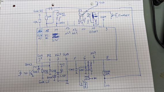
 Bild
 Bild
 Bild