-
 Bild
Bild
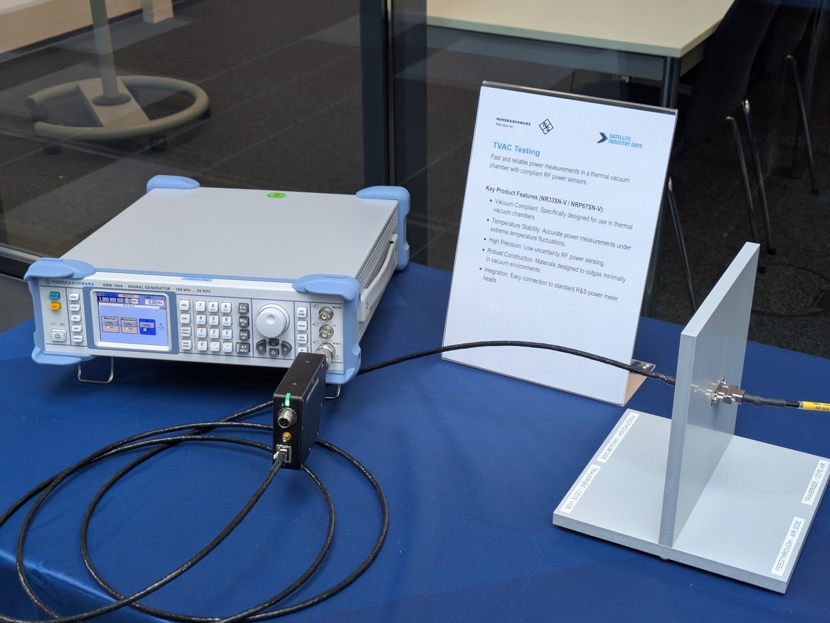
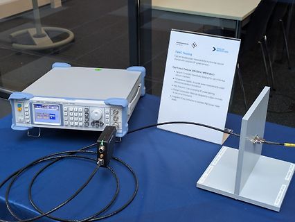
Rohde & Schwarz Signalgenerator und Messaufbau
chambers. • Temperature Stability: Accurate power measurements under extreme temperature fluctuations. • High Precision: Low-duty RF power sensing • Robust Construction: Materials designed to outgas minimally in vacuum environments. • Integration: Easy connection to standard R&S power meter heads.
-
 Bild
Bild
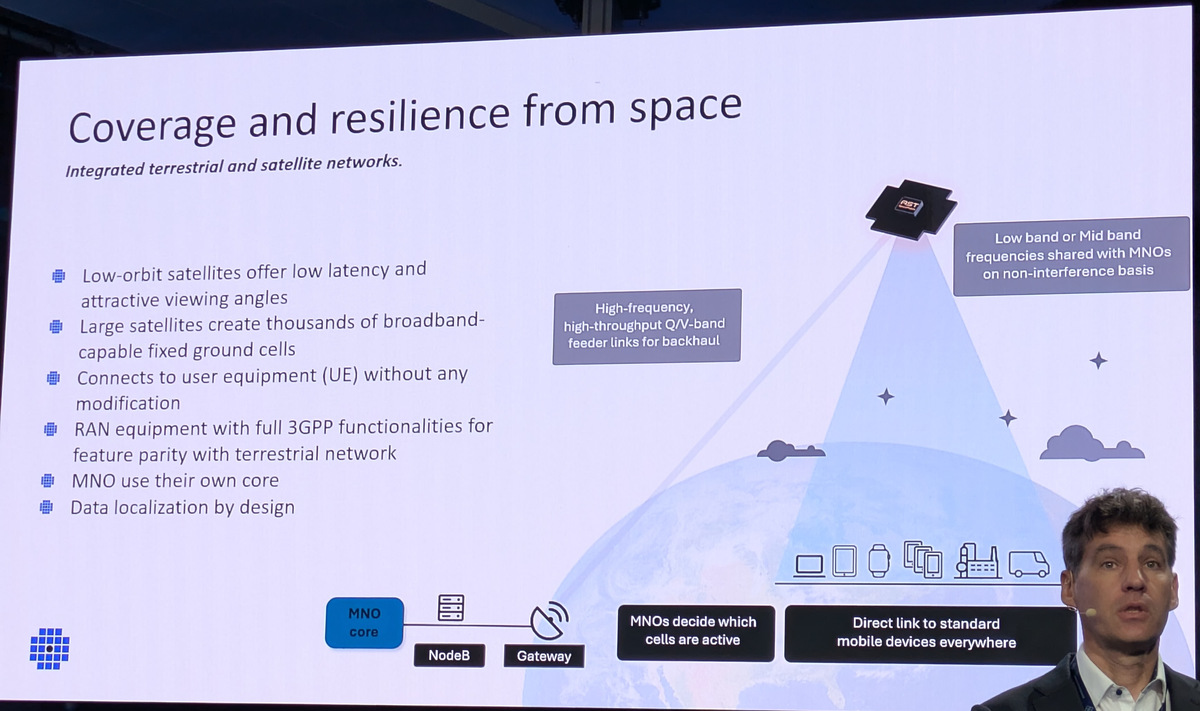
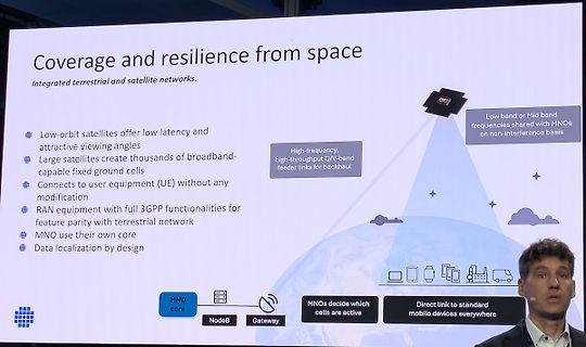
Präsentationsfolie über Satellitennetzwerke und terrestrische Konnektivität
Coverage and resilience from space Integrated terrestrial and satellite networks. Low-orbit satellites offer low latency and attractive viewing angles Large satellites create thousands of broadband-capable fixed ground cells Connects to user equipment (UE) without any modification RAN
-
 Bild
Bild
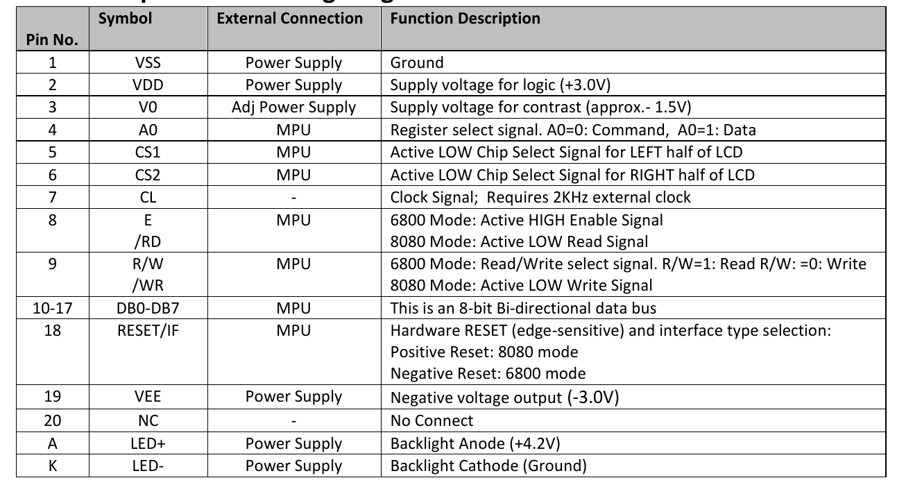
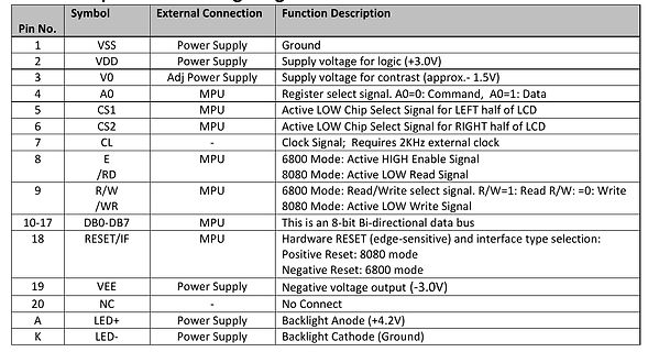
Pinbelegungstabelle eines LCD-Displays
contrast (approx. 1.5V) 4 A0 MPU Register select signal. A0=0: Command, A0=1: Data 5 CS1 MPU Active LOW Chip Select Signal for LEFT half of LCD 6 CS2 MPU Active LOW Chip Select Signal for RIGHT half of LCD 7 CL CL Signal; Requires 2KHz external clock 8 E MPU 6800 Mode: Active HIGH Enable Signal 9 /RD R/W 8080 Mode: Active LOW Read Signal /RW 6800 Mode: Read/Write select signal. R/W=1: Read R/W: =0: Write /WR 8080 Mode: Active LOW Write Signal 10-17 DB0-DB7 MPU This is an 8-bit Bi-directional data bus 18 RESET/IF MPU Hardware
-
 Bild
Bild
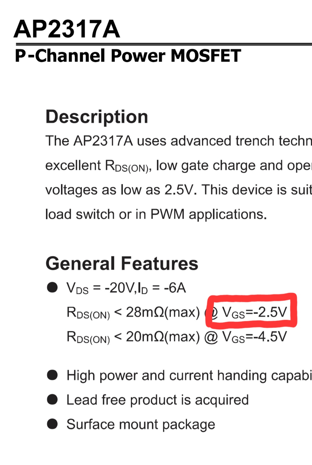
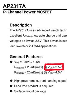
Ausschnitt eines Datenblatts für einen P-Channel MOSFET
AP2317A P-Channel Power MOSFET Description The AP2317A uses advanced trench techn... excellent RDS(ON), low gate charge and ope... voltages as low as 2.5V. This device is suit... load switch or in PWM applications. General Features VDSS = -20V, ID = -6A RDS(ON) < 28mΩ(max) @ VGS=-2.5V RDS(ON) < 20mΩ(max) @ VGS=-4.5V High power and current handi capabi Lead free product is acquired Surface mount package
-
Thread
AI-VNA, 6GHz-Oszilloskop von Rigol, NEC-Frontend uvam
RISC-V cores, a neural processing unit for AI and vector acceleration, post-quantum cryptography, and high-speed Ethernet switching. The consortium spans six European countries and includes NanoXplore Inc., Thales Alenia Space, TTTECH, and Xiphera Ltd., making this one of the most substantive RISC-V space
validation time • Simpler workflows – AI-guided setup reduces complexity and errors • Higher productivity – ultrafast sweeps accelerate R&D efficiency and production throughput • Trusted accuracy – high dynamic range and excellent repeatability ensure reliable results • Lower test
-
Thread
Titel: CAN-Bus: ACK-Bit zeigt doppelte Differenz-Amplitude am Oszilloskop (Setup: Olimex ESP32 & Vic
Mischverbau von High-Speed CAN und Low-Speed CAN Transceivern ?
-
Thread
ESP32 mit 3,3V PWM einen 3,7V Motor betreiben
A maximum of 22 μF is recommended. > Aluminum-electrolytic capacitors are not > recommended for low-temperature applications of <= -25°C https://ww1.microchip.com/downloads/en/DeviceDoc/22057B.pdf Der relativ hohe Ruhestrom des MCP1826 passt allerdings nicht gut zum Deep-Sleep Modus, falls dieser
verkleinern. Aufpassen, dass die Motorspannung nicht zu groß wird, sonst leiten die immer, egal ob der ESP HIGH oder LOW liefert. Viel Spaß noch. Paul -. schrieb im Beitrag #8063060: > es funktioniert mit 10k Richtung > ground und 1k vor dem Gate Wenn es P-Kanal FETs sind, ist es evtl. sinnvoller, den
-
Thread
ESP32-S31-Module verfügbar, WiFi HaLow am Vormarsch, uptonitische Quartalszahlen uvam
Uptonismus nun nach folgendem Schema unter die Roben schauen: [c] Raspberry Pi (LSE: RPI), a leader in low-cost, high-performance computing, is pleased to report that trading in the first half of the year (six months ending ) has been strong, with profitability materially ahead of the comparable period in
im Hause Morse Micro unter https://www.morsemicro.com/2026/06/01/morse-micro-announces-mm8108-m20-high-power-wi-fi-halow-module-to-accelerate-long-range-iot-adoption/ folgendes: [c] Built around Morse Micro’s second-generation MM8108 Wi-Fi HaLow System on a Chip (SoC), the MM8108-M20 brings sub-GHz
-
Thread
Spannung an Ausgangs-Pin Arduino UNO
ich die LED an- und ausschalten, aber sie leuchtet nur schwach. Ich habe gemessen: Ist der Ausgang HIGH messe ich gegen Masse ca. 0V, im Zustand LOW 3,5V. Warum so wenig? Ich erwarte statt 3,5V etwa 5V. Was muss ich verändern, was mache ich falsch? Joachim
Joachim U. schrieb im Beitrag #8060015: > Ist der Ausgang HIGH messe ich gegen Masse ca. 0V, im Zustand LOW 3,5V. Nein. Umgekehrt! Gruss Chregu
-
Thread
Funkamateur Bauteiletester BT2 BX232 Wer kann mir helfen?
github-Repo die passende ist, hier nochmal für alle Fälle die rückgelesene Firmware. Die Fuses sind: low: 0xE2, high: 0xD9, efuse: 0xFC Vermutlich wird es mal wieder jemand brauchen, denn die relativ schlecht schützbaren Eingänge des Controllers sind natürlich der wunde Punkt dieser Geräte.
-
Thread
Alternativer SSB-TX Ansatz => QRP
Nischenthema. Sieht so aus. Simple Antennenverstärker sind gefragter ;-) Kann mich aber auch für low-tech-Themen begeistern. Wollte schon immer mal einen super-stromsparenden, schmalbandigen UHF-Regen.-Receiver mit 3-Port SAW-Filter aufbauen. Auch so ein 2- 4- Transistor Projekt. > Bastle damit
compilieren kann. Auf jeden Fall macht das Sinn. Wenn's kompliziert wird, gehe ich dreistufig vor. Erst "High-Level" in Matlab/Octave, dann in C/C++ auf dem PC und im letzten Schritt erst auf dem uC. Auch da nutze ich zunächst Testdaten vom PC, sonst wird die Fehlersuche zu mühsam. Hatte ich so beim FT8-Decoder
-
Artikel
AVR In System Programmer
). VERALTET ENDE --> Application Notes. AVR910: In-System Programming (PDF, 240 KB) – Die AppNote "Low-cost" In-system programming (AVRISP) beschreibt einen einfachen, kostengünstigen Programmieradapter zur Übertragung von Programmen in den AVR. Auf dem Programmer befindet sich ein Mikrocontroller –
gedacht war. Die großen Vorteile des Dragons sind, dass er alle Programmiermodi beherrscht, inklusive High-Voltage Parallel Programming ("verfuste" AVRs retten), dass er ein natives USB-Interface hat, von AVR-Studio unterstützt wird, und sogar JTAG und debugWIRE ICE / Debugging unterstützt (bei den AVRs
-
Thread
Dual AVR Handheld Programmer DIY
SD Karte) - Akku und Ladefunktion - ATmega328/A/P/PA - ISP Clock 175kHz - Fuses programmieren (Low Fuse, High Fuse, Ext Fuse und Lockbits) - Skip 0xFF in EEPROM Gibt es das vielleicht als fertiges Gerät oder ein DIY Projekt? Natürlich könnte man das auch mit 2 Programmern lösen, aber ein kompaktes
-
Thread
J-Link detekt moeglich?
Nach einem Flashen muss man einen vollen Power Cycle + Kaltstart machen um die Software korrekt inkl Low Power Modes zu testen.
einem Flashen muss man einen vollen Power Cycle + > Kaltstart machen um die Software korrekt inkl Low Power Modes zu testen. Wenn man so Dinge wie "Low Power" realistisch testen will sollte doch auch kein Debugger angesteckt sein (ändert eventuell die Stromaufnahme). Damit hat man den Power Cycle
-
Thread
Induktiver Sensor antwortet nicht auf I2C
ADDR pin high oder low? 0x2B versucht? Manche verstehen den RW bit auch inklusive adresse manche nicht. Mal versuchen 0x2A oder 0x2B durch 2 teilen. Schematic posten wird auch helfen.
; //SOSCDIV1 = 1, SOSCDIV2 = 1 SCG->SOSCCFG = SCG_SOSCCFG_RANGE(3) | SCG_SOSCCFG_EREFS(1); //High frequency range external crystal while(SCG->SOSCCSR & SCG_SOSCCSR_LK_MASK); //Ensure SOSCCSR is unlocked SCG->SOSCCSR = SCG_SOSCCSR_SOSCEN(1); //Enable oscillator while(!(SCG->SOSCCSR
-
Thread
Neue Bauteile: Steckverbinder, Sensoren, Oszillatoren und mehr
Hochspannungs-Widerstände hoher Stabilität The RVCU series offers a voltage coefficient of resistance (VCR) as low as 25 ppm to 50 ppm, depending on resistance value, providing a lower-error alternative to conventional high-voltage chip resistors which may have VCR up to 300 ppm and beyond, for best performance
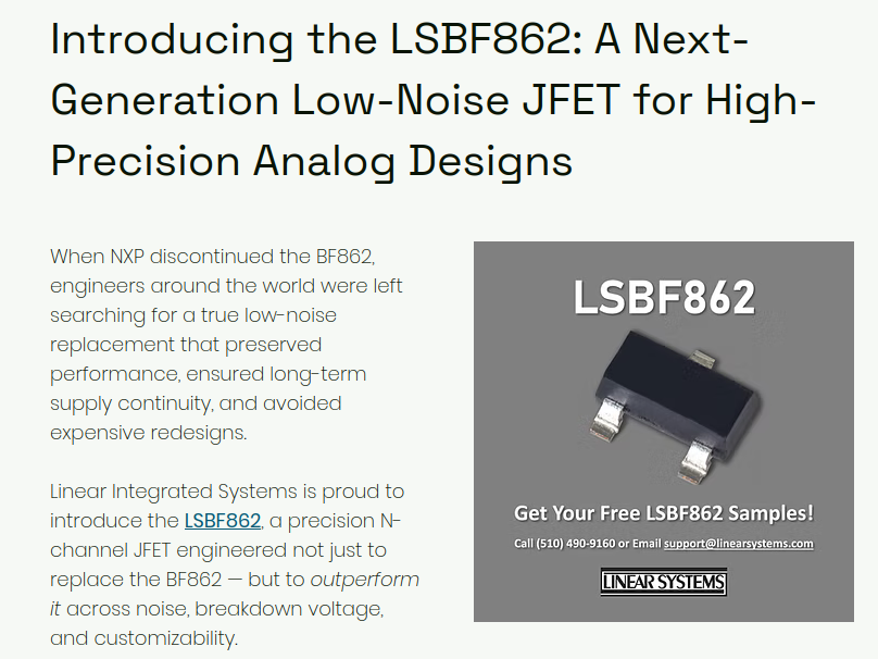
698465/2.png) Bildquelle: https://www.linearsystems.com/post/introducing-the-lsbf862-a-next-generation-low-noise-jfet-for-high-precision-analog-designs (Mit Dank an arnkrens) ### SV Microwave – BNC-Stecker für bis zu 65GHz Wo fortgeschrittene RF-Steckverbinder sind, ist die Torque Wrench meist nicht
-
 Bild
Bild
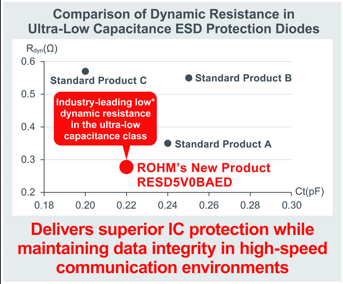
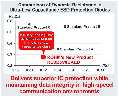
Diagramm zum Vergleich der dynamischen Widerstände von ESD-Schutzdioden
Comparison of Dynamic Resistance in Ultra-Low Capacitance ESD Protection Diodes Rdyn(Ω) 0.6 0.5 Standard Product C Standard Product B Industry-leading low* dynamic resistance in the ultra-low capacitance class 0.4 Standard Product A 0.3 ROHM's
-
 Bild
Bild
Werbung für den LSBF862 JFET
Introducing the LSBF862: A Next-Generation Low-Noise JFET for High-Precision Analog Designs When NXP discontinued the BF862, engineers around the world were left searching for a true low-noise replacement that preserved performance, ensured long-term

-
Thread
TWI1 auf Atmega328PB schlägt fehl
Ordnung. Nach Spezifikation müssen die Daten auf SDA einen stabilen Logikpegel besitzen, während SCL high ist - und das tun sie.
insbesondere auch inclusive Timer4... > Ist der > PB Oszillator wirklich so pingelig? Ja. Alle LowPower-Oszillatoren sind generell diesbezüglich deutlich anspruchsvoller als die FullSwing-Teile der alten Typen.
-
 Bild
Bild
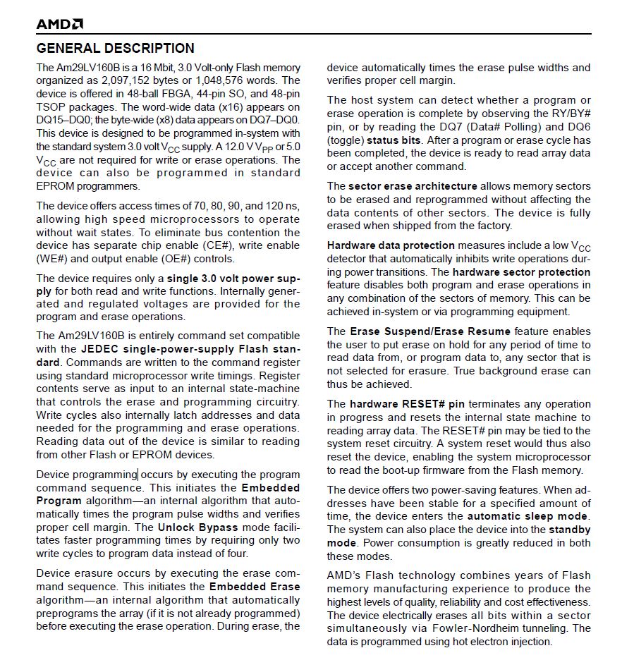
Textauszug eines Datenblatts zum Am29LV160B Flash-Speicher
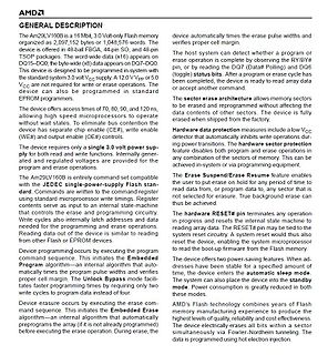
in standard EPROM programmers. The device offers access times of 70, 80, 90, and 120 ns, allowing high speed microprocessors to operate without wait states. To eliminate bus contention the device has separate Chip Enable (CE#), write enable (WE#) and output enable (OE#) controls. The device requires
-
 Bild
Bild
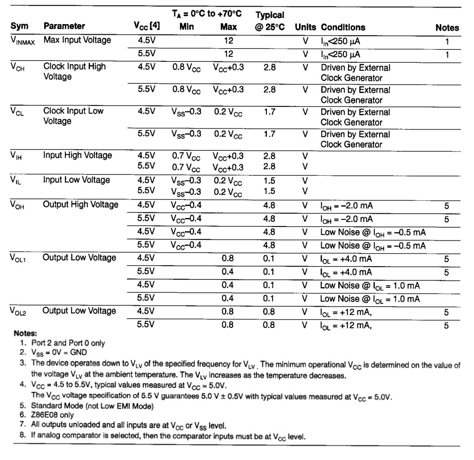
Tabelle mit elektrischen Parametern eines Datenblatts
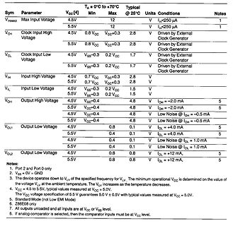
Conditions Notes VINMAX Max Input Voltage 4.5 12 V Iin<250 uA 1 5.5 12 V Iin<250 uA 1 VCH Clock Input High Voltage 4.5 0.8 VCC VCC+0.3 2.8 V Driven by External Clock Generator 5.5 0.8 VCC VCC+0.3 2.8 V Driven by External Clock Generator VCL Clock Input Low Voltage 4.5 Vss-0.3 0.2 VCC 1.7 V Driven by External
-
Thread
Ki Hilft.wenn auch nicht immer
kam allerlei unsinn raus. Habe dann mich erinnert das intern noch ein Port A gibt und einfach High,Low A.0 genommen. hat geklappt. Leider konnte ich die KI nicht davon überzeugen. Der Unsinn der KI das das nicht geht wurde immer größer. Der Alte
_PIN, LOW); delayMicroseconds(BIT_TIME); } // Stopbit digitalWrite(TX2_PIN, HIGH); delayMicroseconds(BIT_TIME); } [/c] der alte [Mod: C-Code in [ c ] ... [ /c ] eingefasst.]
-
Thread
STM32L073RZ läuft auf HSE nur halb so schnell wie erwartet
blinken: [c] void setup() { pinMode(PA5, OUTPUT); } void loop() { digitalWrite(PA5, LOW); delay(500); digitalWrite(PA5, HIGH); delay(500); } [/c] Funktioniert bis dahin. Die Blink-Frequenz der LED bestätigt, dass das Setup korrekt funktioniert. Dann habe ich mir
-
 Bild
Bild
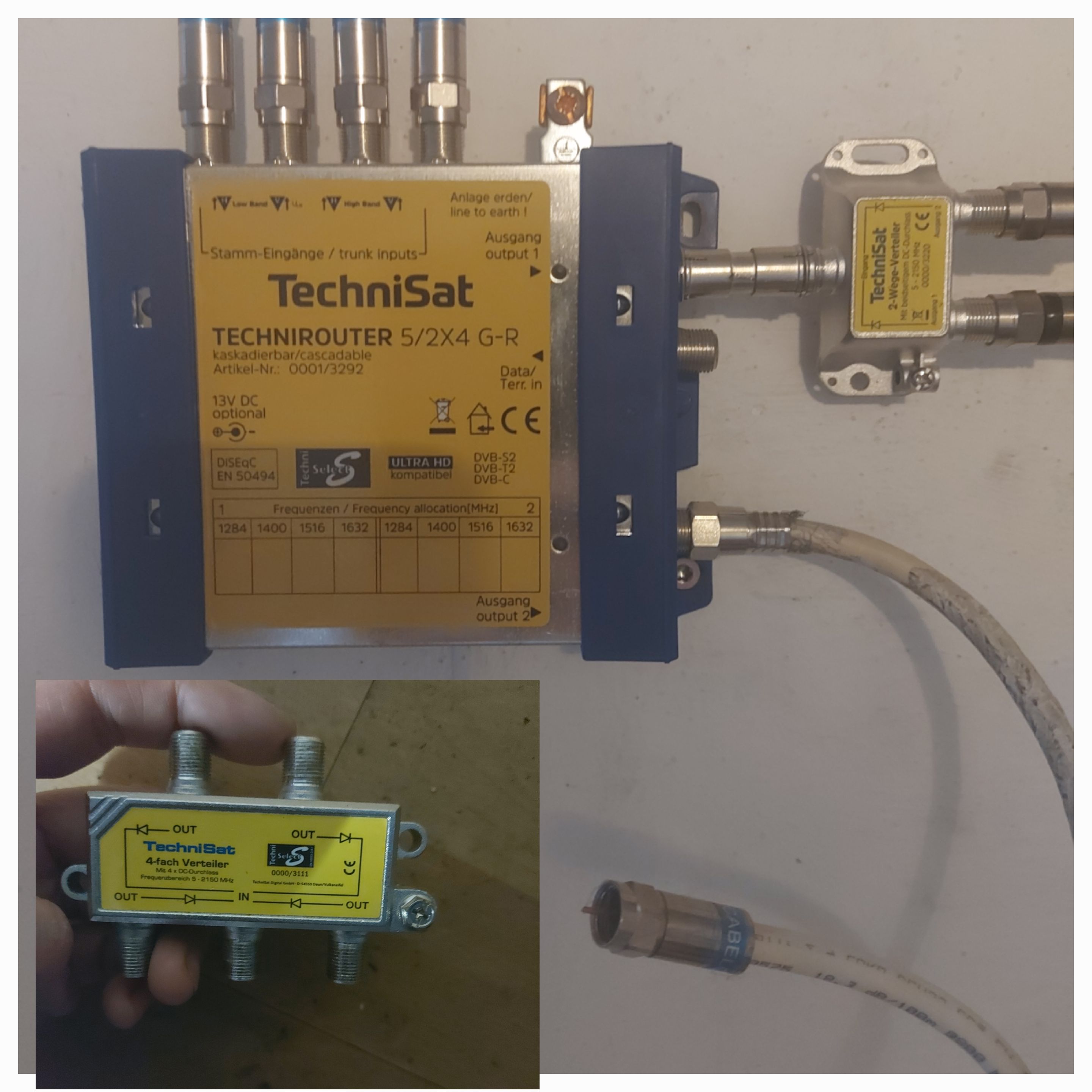
TechniSat Router und Verteiler für Satellitenantennen
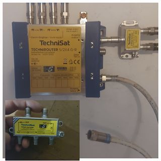
TechniSat TECHNIROUTER 5/2X4 G-R Artikel-Nr.: 0001/3292 13V DC optional Low Band 11-65, High Band 950-2150, Anlage erden/line to earth, Ausgang output 1, DVB-S2, DVB-C, DVB-T2, Frequenzen/Frequency allocation (MHz) 1284 1400 1516 1632, Ausgang output 2, TechniSat 2-Wege-Verteiler
-
Thread
Sat schüssel + verteiler , kein bild
zwei Kabeln. Oben sind die vier Eingänge von den "klassischen" LNBs an der Schüssel (hor/vert/ LowBand/HighBand), rechts sind die zwei Ausgänge zu den Unicable-Empfängern, jeder Ausgang kann vier Unterbereiche, also maximal acht Empfänger. Ist der wirklich defekt? Das ganze entwickelt sich allmählich
-
Thread
Frage zur Beschaltung eines PIC12F1840 zur Abfrage von Widerstandswerten
der Taster und des Potis > programmtechnisch realisiert? Man könnte den Pin kurz auf Ausgang und High schalten, dass der 10nF Kondensator geladen wird. Und dann den Pin auf Eingang umschalten und messen wie lange er braucht, um Low zu werden. So ähnlich wurden ganz ohne ADC z.B. die Joysticks am
-
Thread
DS1621 mit Arduino Uno in SimulIDE 1.1.0-SR2 at Rev 260312
"); Serial.print(temp); Serial.println(" °C"); } float readTemperature(){ int temp_high = 0; int temp_low = 0; Wire.beginTransmission(DS1621_ADDR); Wire.write(CMD_READ_TEMP); Wire.endTransmission(); Wire.requestFrom(DS1621_ADDR, 2); if (Wire.available()>=2) { temp_high= Wire.read(); temp_low= Wire.read(); } float temperature = temp_high; return temperature; } [/c] Stimmt diese oder sind die von ChatGPT generierten Lösungen mit Vorsicht zu
-
 Bild
Bild
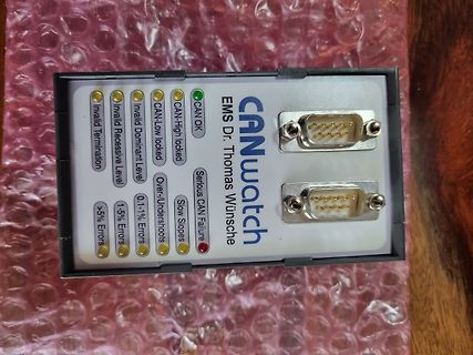
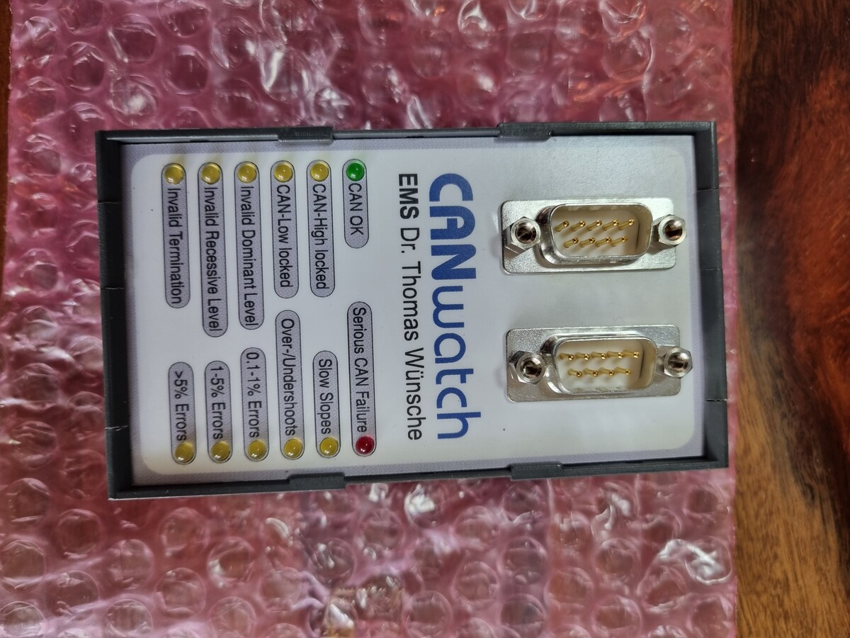
CANwatch Messgerät mit Status-LEDs und DB9-Anschlüssen
CANwatch EMS Dr. Thomas Wünsche CAN OK CAN-High locked CAN-Low locked Over-/Undershoots 0.1-1% Errors Invalid Recessive level Invalid Termination >5% Errors Serious CAN Failure