Modifications to the PM2519/51 .. 2 . . . eee eee eee eee eee eee e e e OS 10. C O M P O N E N T D A T A 10-1 1 1. T E C H N I C A L D A T A , by the manufacturer.nthisdescriptionare nominal; those givenwith tolerancesarebindingandguaranteed 11. G E N E R A L Manufacturer :PHILIPSHIGS&I Type number P M 2519
ein Vorschlag. https://www.thomann.de/de/tascam_portacapture_x8.htm https://www.thomann.de/de/zoom_h1essential.htm https://www.amazon.de/Olympus-Hi-Res-Audio-Rauschunterdr%C3%BCckung-Sprachbalance/dp/B01BI064FK?th=1 Aber nun hast du ja schon ein umfangreiches Setup, nimm das halt. man muss da auch
. ZB. An7:58,8:01,8:05,8:07,8:10,8:15,8:34,8:37,8:38,8:39,8:40,8:44 Aus. ZB. An9:01,9:03,9:09,9:11,9:15,9:16,9:22,9:24An,9:24Aus,9:26,9:40,9:41Aus. Er war nichtzu Hause. An10:43,10:46,10:47,10:50,10:51,10:54,10:55,10:56,10:58An ZB. Aus11:02,11:04,11:07,11:30,11:32,11:33,11:40,11:44,11:45,11:51,11
the other hand, the widths of the multiplication and addition stages grows significantly: a 5b and an 11b adder is so small (1.650ns vs. 1.742ns) The multiplier now has a (52+1)b wide multiplicand B that we can choose the more area efficient 11b distribution M without a significant performance penalty. In
A Control A Control A Control B acc_op_rdy op_last L-stage 1-bit L-stage 1-bit L-stage 1-bit L-stage 1-bit result_rdy Shift Register Shift Register Shift Register final_add Shift Register 1 2 N N+1 Fig. 6. The internal architecture of the modular fully
2) V ee= 5 v. IF= 10 mA 40 110 µcd hp Wavelength at Peak Emission 640 655 670 nm ~;\ V ee= 5 v, V L E o= 4V Spectral Bandwidth 20 nm V1H High-Level Input Voltage 2 v V1L Low-Level Input Voltage 0.8 v V1K Input Clamp Voltage V ee= 4.5 v, 11 = -1 2 mA -1 .5 v l1H High-Level Input Current V ee= 5.5 v, V1=2.4 V 150 µA l1L Low-Level Input Current V ee= 5.5 v, V1=0.4 V -1 mA Irow Row Input Current l Row 1 thru Row 6 500 800 J Row7 See Note 3 600 1000 mA Ice Logic Supply Current 45 65 NOTES: 2. Luminous
und auch sonst ;-). Auflösung der Anzeige ist nicht alles. Im Handbuch zum GDM-9061 ist für den 1A-Messbereich ein Jahr nach Kalibrierung ein Fehlerbereich von 0,01% von 1A spezifiziert, d.h. 0,00010 A oder 100 µA. Ohne Gegenmessung eines bekannten Stromes (Feststellung der aktuellen Kalibrierung
auch sonst ;-). > Auflösung der Anzeige ist nicht alles. > > Im Handbuch zum GDM-9061 ist für den 1A-Messbereich ein Jahr nach > Kalibrierung ein Fehlerbereich von 0,01% von 1A spezifiziert, d.h. > 0,00010 A oder 100 µA. > > Ohne Gegenmessung eines bekannten Stromes (Feststellung der aktuellen
. Im Anhang ein Vorschlag mit viel höherer Geschwindigkeit (~40ns Verzug, Schaltfrequenz jetzt 1MHz) und viel weniger Strom bzw. Verlustleistung. Die Schaltung kann man direkt übernehmen. Auch bei dieser Schaltung ist die Ugs auf ~-11V begrenzt.
Emitterfolger, wenn an der Basis 5V anliegen, dann liegen am Widerstand 390Ω maximal rund 4,4V an. D.h. durch den Widerstand fließen rund 11,3mA. Bei einem Stromverstärkungsfaktor von 50...100 ist der Strom im Kollektorkreis nur minimal geringer. Bei 11,3mA fallen daher an dem 1k Widerstand maximal 11,3V
HCPL-xx3x B C D DK e F R U Broadcom Cosmo CT-Micro Everlight Isocom LiteOn ONSemi Toshiba Vishay HCPL-0700/1 TLP2403 SO8 Broadcom ONSemi Toshiba CNY17 DIP6 70 — 160 50 ton 14 µs, toff 63 µs B C D DK e F U R Broadcom CT-Micro Everlight Isocom LiteOn, ONSemi QT-Brightek Vishay H11L1 VOH1016A DIP6 16 16 digital
counting mode offers very high immunity to such variations compared to the analog mode. (See Figure 6-11.) ) D 2.6 H T M 2.4 ) G O I ANALOG METHOD (a) H T E U 2.2 M O G C L O 2.0 A T A H ( ( 1.8 I E G T I R 1.6 E T G U A O 1.4 H C C I PHOTON COUNTING E METHOD (b) N 1.2 A H C 1.0 1.00 1.02 1.04 1.06 1.08
64-bit) • macOS® (minimum version OS X® Yosemite) [/CODE] Die erfülle ich mit meinem Windows 11 natürlich nicht ... Viele Grüße Igel1
Im USB-DFU Mode ist das Display aus, ebenso alle LEDs. Es wird der ROM Bootloader des STM32L496 verwendet. Hast Du schon geprüft ob die USB Datenleitungen zum STM32L496 gehen? Das sind: [code] Pin 70 PA11 - OTG_FS_DM Pin 71 PA12 - OTG_FS_DP [/code]
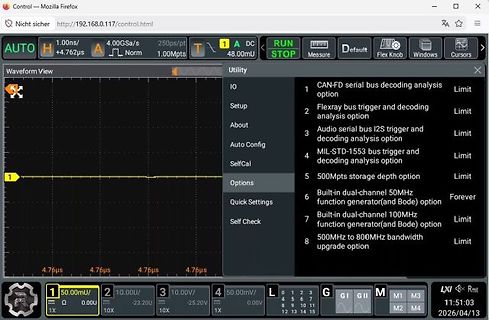
Control — Mozilla Firefox http://192.168.0.117/control.html Nicht sicher AUTO H 1.00ns / +4.762us 4.00GSa/s Norm 1.00Mpts DC 48.00mU RUN STOP Measure Default Flex Knob Windows Cursors Waveform View Utility IO CAN-FD serial bus decoding analysis option Limit Setup Flexray bus trigger
das eine Led 2 Sekunden leuchten läßt und währenddessen ein Thermometer Und Feuchtigkeitsmesser (dht11) ausliest. Hier der Code: [c] #include <stdio.h> #include <math.h> #include "pico/stdlib.h" #include "hardware/gpio.h" const uint LED_PIN = PICO_DEFAULT_LED_PIN; //const uint DHT_PIN = 15;
+ 32; printf("Humidity = %.1f%%, Temperature = %.1fC (%.1fF)\n",reading.humidity, reading.temp_celsius, fahrenheit); } l=l+1; nix_schalter = true; // nix_schalter auf true setzen, damit er beim nächsten Durchlauf
BEDIENUNGSANLEITUNG (German) MODE D’EMPLOI (French) GEBRUIKERSHANDLEIDING (Dutch) ANVÄNDARHANDBOK (Swedish) LS902UT H I L USER MANUAL G E ENGLISH TABLEOFCONTENTS DEUTSCH FOR YOURSAFETY....................................1....................... SAFETYPRECAUTIONS.............................1.............. FRANCAIS CUSTOMERSERVICE
drive the power stage as shown in Figure 31. http://onsemi.com 21 AN1543/D 0 n V n V N 3 0 5 4 0 5 8 C 1 2 C 1 2 T F V M 0 0 C 6 1 E E 5 1 H 5 8 L m 8 3 T 1 4 T 3 Q M 1 3 Q M 1 C C k 7 7 1 0 2 5 C 2 6 C R 3 8 Q B 8 Q B W 5 1 6 1 9 l D N D N R 0 1 1 1 1 W R / R 1 k R 1 k 7 R 0 R 1 R 0 R 1 4 1 1 1 1 T T 5
(Type A) USB 2 x USB 2.0 Host (Type A) (optional) Ethernet 2 x 1 GB Ethernet Communication 1 x RS-232 or RS-422 or RS-485 (Can be set via BIOS) Video 1 x DVI WLAN 1 x 802.11 ac/a/b/g/n 2.4 GHz, 5 GHz, (optional) Power Connector Phoenix Connector side Touch-it XELO
H. H. schrieb im Beitrag #8034882: > Edit: Und mittlerweile bin ich recht sicher, dass es Panasonic SP-Cap, > Serie L, sind. Zum Testen könnte ich dann trotzdem meine 6V 330 uF versuchen, wenn die
. 350 uF, beide. ESR -Wert weiß ich nicht. An dem L3 messe ich nun die ca. 1,8 Ohm. Genauso an den N-Channel, unten an der Kante im Bild bei der L3. Mit der ca.-Leistung von 40Watt des Nvidia-Chips könnten so ziemlich niedrige Ohmwerte messbar sein
breq .L1 rcall abort .L1: movw r24,r20 ret .ident "GCC: (GNU) 17.0.0 20260626 (experimental)"[/pre] Die einzige Frage ist wieviele Leute es gibt, die sich mit Rust auskennen UND mit AVR auskennen
Rick schrieb im Beitrag #8070173: [c] #include <stdio.h> // printf void main( void) { int i, j; i = 0; j = 1; while( j > i) { i++; j++; } printf( "%d %d\n", i, j); } [/c] Der Code ist UB
The line can be connected to an interrupt input of the host system, for example.. I²C - Address Pin 11,7,6 Base I²C address address D7 D6 D5 D4 D3 D2 D1 D0 BA2 BA1 BA0 L L L $10 0 0 0 1 L L H $20 0 0 1 0 L H L $30 0 0 1 1 S S S L H H $40 0 1 0 0 A A A R H L L $70 0 1 1 1 2 1 0 W H L H $90 1 0 0 1 H H L $B0 1 0 1 1 H H H $D0 1 1 0 1 all pins open: Write $DE Read $DF DATATRANSFERI²CINTERFACE principle I2C-bus transfer: -I²C-Start - Master-Transmit: EA eDIP-I²C-address (e.g. $DE), send smallprotocol package
2333.21103-10 2.2 PIO-Belegung (Empfänger-Kommandierung und Rückmeldung) BU 4, 5, 6 und 7 T52/R BU 60 1 Empf%onger PIN PIO PIO PIO 1200 4 Port A 1 Bit 7 4 EinstelH:>eräter. bit 14 3 6 3 2 5 2 1 4 1 3 - 35 2 47 Aufforderung Rückmeldung 10 1 11 EinstelH:>ruppen Nr. bit 10 :"~. 9 0 10 .::.!I 8 Port B 1 bit
2333.21103-10 2.2 PIO-Belegung (Empfänger-Kommandierung und Rückmeldung) BU 4, 5, 6 und 7 T52/R BU 60 1 Empf%onger PIN PIO PIO PIO 1200 4 Port A 1 Bit 7 4 EinstelH:>eräter. bit 14 3 6 3 2 5 2 1 4 1 3 - 35 2 47 Aufforderung Rückmeldung 10 1 11 EinstelH:>ruppen Nr. bit 10 :"~. 9 0 10 .::.!I 8 Port B 1 bit
Springer-Verlag 1968 216 S. Grauer, Lieb Differential- und Integralrechnung III Springer-Verlag 1968 177 S. H. Heuser Lehrbuch der Analysis Band 1 B. G. Teubner 15. Aufl. 2003 643 S. H. Heuser Lehrbuch der Analysis Band 2 B. G. Teubner 12. Aufl. 2002 737 S. L. Hogben Die Welt der Mathematik Deutsche Buch-Gemeinschaft
Christoph db1uq K. schrieb im Beitrag #8034616: > Auf Youtube kann man 3 1/2 Stunden Apollo 11 anschauen. Und auch Erklärung wie zB AGC (Apollo Guidance Computer) funktionierte, etwa Fädelspeicher: https://
… ohhh … wait … "You gonne blow up the moon?" Zack ;-) https://www.youtube.com/watch?v=tL1OATdBoY8
total cost: $16.93 1-800-346-6873 Volum,Number3 COMMODORE WORLD AUDIO DIGITIZER SCHEMATIC USER POHT J (7 I« HW.B(1 AB CD EFH J K L" H h whJtalookinginlesin.poM hom irnnil olIhiWilt) (vl IDjlF UtWI C| !■-, 3n 31sn1 cnecigItoisl
Christoph db1uq K. schrieb im Beitrag #8030613: > https://de.wikipedia.org/wiki/Lese-_und_Rechtschreibst%C3%B6rung Wie gut, dass du über andere urteilen kannst. Wenn man fachlich nichts beitragen kann, mach man
Christoph db1uq K. schrieb im Beitrag #8031293: > Dass gleich mehrere Autoren zu einem "uralten" Bauteil die Bezeichnung > falsch schreiben ist seltsam. Du vergisst, dass der Zugang zu diesem Forum oft über PCs
auch nicht genau nach Bauvorschlag aufgebaut, bzw aufbauen können. Die Antenne ist unterm Dach, d.h. hängend unter der Firstfette. Da das Haus nur 12m lang ist, mussten die 80m-Drähte hinter den Verlängerungsspulen abgewinkelt werden. Außerdem wurde nur 1,1mm Cu-Draht statt 2,0mm Draht genommen. Macht
liegt doch ziemlich dicht dran. Der SWR im 80m-Band ist etwas besser als in der Simulation, der im 11m Band etwas schlechter. Im Bild der Scan vom VNA, die Amateurbänder unterlegt. Das 80m-Band nochmal im zweiten Bild vergrößert und ein zweiter Scan mit einem vorgeschalteten 1:1,5-Übertrager. Der
under different conditions. www.onsemi.com 4 MOC3081M, MOC3082M, MOC3083M TYPICAL PERFORMANCE CURVES 1.7 1.6 1.6 1.5 VTM = 3 V ) 1.5 NORMALIZED TO T A = 25_C ( 1.4 E 1.4 A L D1.3 O 1.3 T = −40_C I V A L R 1.2 M1.2 A TA = 25_C R W 1.1 O O ,1.1 F TA = 85_C I F 1.0 V 0.9 1.0 0.8 0.9 0.7 0.1 1 10 100 0.8
Operating Frequency Band 2.4GHz -2.48GHz unlicensed ISM band PDFmyURL.com Bluetooth Specification V2.1+EDR Output Power Class Class 2 Operating Voltage 3.3V Host Interface USB 1.1/2.0 or UART Audio Interface PCM interface Flash Memory Size 8Mbit Dimension 27mm (L) x 13 (W) mm x 2mm (H) Electric Features
1 - ( - 1 , > 1N"> ~ e '~ Q .ntQ • .N0> - v -3 . 0,.J 1 + ~ i J ~ jJ:1 C N-> 1G •1 1 ! 1 11 1 i 11 1 ~' > 1 " t . 3 1 1 1 y E 11 a ' u" n S ;1 O m m> : i + h N L' s r t e \ e z r ~ 2 N + - > h g i : a
Helmut H. schrieb im Beitrag #8032553: > Milchmädchen rechnet mit dickem Daumen: aus 1 Barrel Rohöl wird 70 Liter > Diesel/Heizöl (leicht) > ... Aus den 159l Rohöl werden (mindestens) 130l Diesel.
Roland E. schrieb im Beitrag #8032638: > Helmut H. schrieb: >> Milchmädchen rechnet mit dickem Daumen: aus 1 Barrel Rohöl wird 70 Liter >> Diesel/Heizöl (leicht) >> ... > > Aus den 159l Rohöl werden (mindestens) 130l Diesel. Da bleibt aber
warst du das letzte mal im Harz? https://www.google.com/maps/@51.7813446,10.5509217,3a,90y,287.8h,88.55t/data=!3m7!1e1!3m5!1sOT3Rt7NEDDHtB3H1Mgxmtg!2e0!6shttps:%2F%2Fstreetviewpixels-pa.googleapis.com%2Fv1%2Fthumbnail%3Fcb_client%3Dmaps_sv.tactile%26w%3D900%26h%3D600%26pitch%3D1.4524656371671654%
warst du das letzte mal im Harz? > > https://www.google.com/maps/@51.7813446,10.5509217,3a,90y,287.8h,88.55t/data=!3m7!1e1!3m5!1sOT3Rt7NEDDHtB3H1Mgxmtg!2e0!6shttps:%2F%2Fstreetviewpixels-pa.googleapis.com%2Fv1%2Fthumbnail%3Fcb_client%3Dmaps_sv.tactile%26w%3D900%26h%3D600%26pitch%3D1.4524656371671654%
type identification is located in the bits 4 to 7 and factory programmed for all PCF7936AS devices to 1H, as shown in Figure 5. 2010 May 04 8 CONFIDENTIAL NXP Semiconductors Product Specification Security Transponder (HITAG2) PCF7936AS Page 3 Lock, PG3L 7.1.3 Secret Key, SK If set, page 3 is irreversible
W5500 DNC 7 30 XI/CLKIN AVDD 8 48LQFP 29 GND AGND 9 28 VDD EXRES1 10 27 ACTLED AVDD 11 26 DUPLED NC 12 25 LINKLED 0 1 2 3 4 1 1 1 1 1 1 1 2 2 2 2 2 C D D D D G D P D O D D N G V G V V G C V V S L A A A A A T A 1 R P S Figure 1. W5500 Pin Layout 1.1 Pin Descriptions
werde. Jedoch löst es nicht das Problem. Folgendes habe ich auf der Platine geändert: - zw. Pin1 und 14 einen Kondensator (1uF) eingesetzt - Pin11 von Vcc getrennt und mit einem Bypass-Ko (1uF) versehen (gegen GND) - Pin4 (RST) von PullUp (R3) getrennt (wie Adafruit) - USB-Schirm vom GND entfernt
Also, mir bitte nicht gleich den Kopf abreißen. Die Datenleitungen (D+ und D-), sowie Vss und Pin11 sind sauber auf den Pads gelötet, die direkt an die USB-Pins gehen. Lediglich Pin 1 (Vdd) Pin4 RST) musste ich mit Litzen mit den zugehörigen Bauteilen verdrahten. Die anderen Pins liegen in der Luft
// Programm für Arduino Giga mit Bildschirm // Giga_011_Poti_Scala // LED_PR1 = D51/PE5, LED_PR2 = D40/PE6, PR1 = A11/PA0_C, PR2 = A10/PA1_C // Arbeit mit class als Lib, Variante mit Zeiger // Sketch uses 160320 bytes (8%) of program storage space. Maximum is 1966080 bytes. //

 Bild
Bild
 Bild
Bild
 Bild
Bild
 Bild
Bild
 Bild
Bild