Deine SPI Read- und Write-Funktionen sind doppelt gemoppelt, es genügt _eine_ Funktion (SPI Transfer) die sowohl ein Byte schreibt und bei der Rückkehr ein gelesenes Byte liefert.
Wastl schrieb im Beitrag #7881400: > im letzten Transfer > kommt ein zu lesendes Byte daher. Chip Select rahmt die vier > Transfers ein. Ist alles glasklar im Datenblatt beschrieben. Was ist daran nicht zu verstehen? Ist dir der Mechanismus des SPI
anderen Architekturen heutzutage oft wegoptimiert wird. Und so macht das GCC ja auch. Aber der Transfer von XYZ zum SP ist nicht atomar und das ist bei Interrupts entscheidend. > Ich programmiere recht viel in Assembler Die Problematik bezieht sich auf C. In Assembler liegen lokale Daten selten
> Aber der Transfer von XYZ zum SP ist nicht atomar > und das ist bei Interrupts entscheidend. Das sollte eigentlich kein Problem sein, da der AVR beim Interrupt-Aufruf weitere Interrupts blockiert. Man kann SPH/SPL
differential 400-700 mV Drive voltages 3.3 V, 5 V, 12 V Jumpers for configuring drive N/A Data transfer rate 6.0 Gb/s SATAharddrivecables SATAdatacable Always use an HP approved SATA 6.0 Gb/s cable as it is fully backwards compatible with the SATA 1.5 Gb/s drives. Current HP desktop products ship with
request logic to support one or more peripherals' access requests to the memory. The access priority, transfer length, source address and destination address of the transfer can be configured. The main peripherals used by DMA include: general-purpose/advanced-control/basic timers TIMx, DAC, V1.4 6 CH32V003
Interface : Serial ATA Major Version : ACS-4 Minor Version : ACS-4 Revision 5 Transfer Mode : SATA/600 | SATA/600 Power On Hours : 12860 Std. Power On Count : 1276 mal Host Writes : 30796 GB Wear Level Count : 12 Temperature : 44 C (111 F) Health Status : Gut
Optokopplers steht, mit welchem Strom er mindestens betrieben werden sollte. Dabei ist der CTR (Current Transfer Ration) wichtig. Ein CTR von z.B. 100% bedeutet, das der OK 5mA schalten kann, wenn er mit 5mA angesteuert wird.
zuerst ein Beschreiben des Framebuffers und ggf. einem Setzen des Dezimalpunktes mit anschließendem Transfer zum Chip. Funktionen für ein 16-Segment Digit sowie ein Einlesen von Tasten sind (noch) nicht realisiert, weil dem Autor zum einen keine 16-Segmentanzeigen zur Verfügung stehen und für mehr als eine
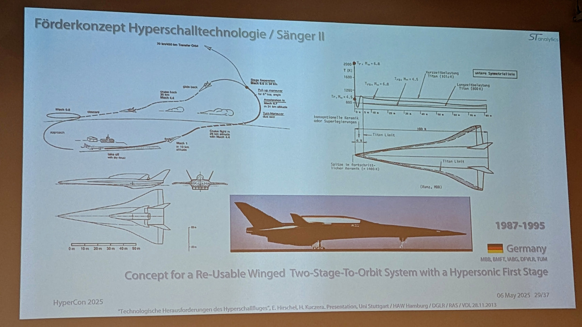
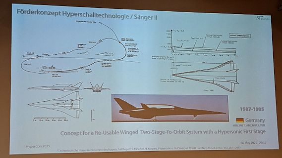
Förderkonzept Hyperschalltechnologie / Sänger II
70 km/400 km Transfer Orbit
Stage Separation Mach 8.5 at 50%...
Crab back 30 km Mach 6.4
Mach 6.6
approach
take off with thrust
Mach 1 in 10 km altitude
Crab flight in 30 km altitude with Mach 4.4
Turn maneuver due to.
BCC 17) 18) 19) 5) 20) 7) 8) 6.3.9 Data message (programming mode) Used for block oriented data transfer, see also 6.5 and flow charts in the annexes. STX Data set ETX BCC 5) 20) 6) 8) 6.3.10 Data message (programming mode) using optional partial blocks Used for long messages of block oriented data transfer
for SPI2. pDmaRx: Use the DMA channel supported by the selected SPI for transfer from peripheral to buffer, like DMA1_Channel4 for SPI2. dmaClearMask: Use bitmask which clears the transfer complete or error state of the selected pDmaTx and pDmaRx. example: DMA_IFCR_CGIF4 | DMA_IFCR_CGIF5
UCR is transferred to bit 9 in the Transmit Shift Register. On the Baud Rate clock following the transfer operation to the Shift Register, the start bit is shifted out on the TXD pin. Then follows the data, LSB first. When the stop bit has been shifted out, the Shift Register is loaded if any new data
completed 2021/09/08 Add detailed explanation of TA652. 2021/09/10 TA642 and TA652 add temperature transfer. TA632 fix data description Timestamp is 32bits 2021/09/22 TA632 remove Timestamp 2021/09/27 Version number changed from 8bits to 16bits TA652 Weighted data changed to 16bits Upload data description
supply. Sensitivity [High] [Low] High High: for sensitive equipment, In/Out settings UPS will easily transfer to battery when utility conditions are becoming bad. Low: for equipment that can withstand bad utility conditions, in that case, the UPS will not transfer to battery. Load segments - [No Delay] [1
beigefügtes Manual Seite 11 Preisvorstellung: 50€ zzgl. Versand Meine Idealvorstellung für den Transfer: Überweisung via Paypal, ich bekomme vie Mail einen Hermes-Paketschein-Code. Den kann man einfach online kaufen. Die eigene Adresse als Absender und Empfänger angeben. Vorteile dieses Verfahrens
Applying The wires can be bundled or deposited in n Excellent accessibility and safety the loop transfer principle, the device predefined order as a chain. n Expandable feeds the two wire ends of the loop indi- n Prepared for Zeta 651 and Zeta 655 vidually one after the other to the appro- machines priate
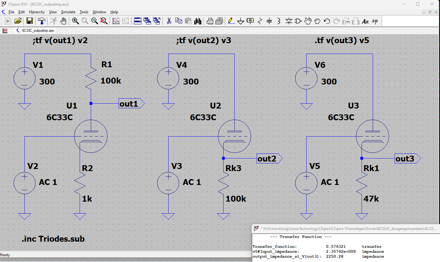
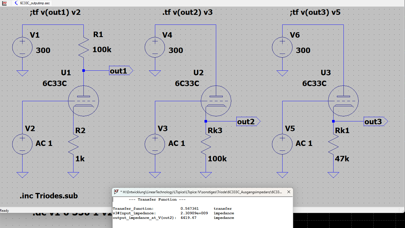
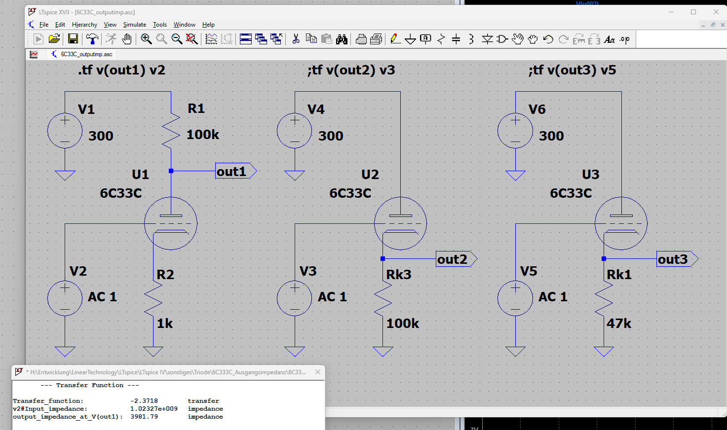
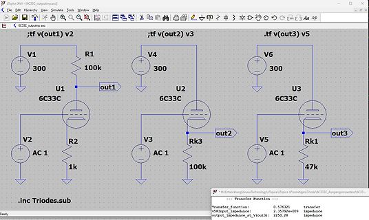
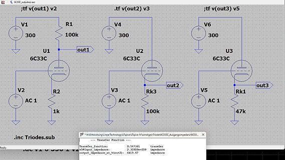
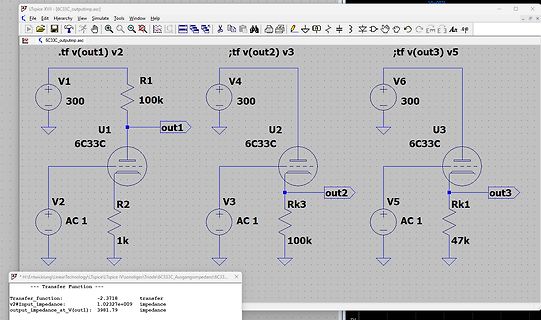
Simulation-von-Roehrenschaltungen-mit-Spice.html Bei Röhrenschaltungen ist für die Impedanzbestimmung die DC- Transfer-Funktion zielführender. Für Endstufen kommt 6C33C_outputimp__out1.png infrage. Hier muß jetzt der Kathoden- und Anodenwiderstand noch angepasst werden. Aber dies sollte für das Erste genügen
Simulation-von-Roehrenschaltungen-mit-Spice.html > > Bei Röhrenschaltungen ist für die Impedanzbestimmung die DC- > Transfer-Funktion zielführender. > > Für Endstufen kommt 6C33C_outputimp__out1.png infrage. Hier muß jetzt > der Kathoden- und Anodenwiderstand noch angepasst werden. > > Aber dies sollte für das Erste
Relaispolwechslerschaltung arbeitet mit einer Eingangs-Gleichspannung von 6 V und gibt je nach Übersetzungsverhältnis des TransfOl'mators eine Ausgangs wechselspannung von 20 bis 100 V mit einer Frequenz von etwa 20 bis 25 Hz ab. In der Versuchsschaltung fanden zwei mittlere Rundrelais BV-Nr. 4722:30-554 Verwendung. TI' 114,2
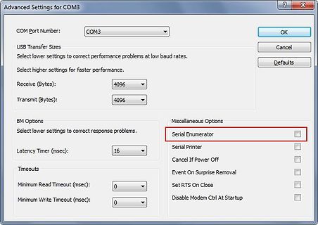
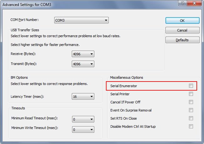
Advanced Settings for COM3
COM Port Number: COM3
OK
Cancel
Defaults
USB Transfer Sizes
Select lower settings to correct performance problems at low baud rates.
Select higher settings for faster performance.
Receive (Bytes): 4096
Transmit (Bytes): 4096
BM Options
Select lower settings
tHSSISGn _CSIGnSSI Hi-Z CSIGnSO 7.8 UART timing Ratings Parameter Symbol Condition Unit Min Typ Max Transfer rate - - 1.5 Mbps R01DS0145EJ0102 41 Data Sheet Chapter 7 Peripheralsspecification 7.9 FCN timing Ratings Parameter Symbol Condition Unit Min Typ Max Transfer rate - - 1 Mbps Internal delay time tINTDEL
parties to make or receive copies. Mere interaction with a user through a computer network, with no transfer of a copy, is not conveying. An interactive user interface displays "Appropriate Legal Notices" to the extent that it includes a convenient and prominently visible feature that (1) displays an appropriate
. At the compressor suction connector the temperature must be approx. ambient temperature. Thus transfer of moisture to the refrigerator insulation is avoided. Systems with an expansion valve must be charged with refrigerant until there are no bubbles in the sight glass, which should be placed as close
Bausteine. Silabs CP2110-F01-GM QFN24, 4 x 4 mm, Siehe Bild Single-Chip HID USB to UART Data Transfer also seriell RX/TX wird als Windows HID erkannt. ALso z.B direkt in eine Textdatei eingeben. https://www.mouser.de/ProductDetail/Silicon-Labs/CP2110-F01-GM?qs=j12q4iUN960yL%2FAK09Hgyg%3D%3D
CP2110 S INGLE -C HIP HID USB TO UART B RIDGE Single-Chip HID USB to UART Data Transfer UART Interface Features Integrated USB transceiver; no external resistors Flow control options: required - Hardware (CTS / RTS) Integrated clock; no external crystal required - No flow control
Programmierung angeht. Welche Mengen an Daten schickt ihr auf das Display das Aufbereiten und Transfer so lange brauchen? Gut, aktuell hab ich noch Probleme mit Lowercase Charakter, die werden einfach Uppercase dargestellt (aber immerhin nicht falsch!) bei dem Display der Fumot 25000. Aber Verzögerungen
Beitrag #7860355: > Welche Mengen an Daten schickt ihr auf das Display das Aufbereiten und > Transfer so lange brauchen? Der eigentlich Datentransfer geht per SPI für 900x480 Pixel mit je 8 Bit (wovon nur 4 genutzt werden) in weniger als einer Sekunde. Das Geflimmer veranstaltet tatsächlich der
Changing the I bit through the I/O register results in a one-cycle Wait state on the access. Bit 6 – T Transfer Bit The bit copy instructions, Bit Load (BLD) and Bit Store (BST), use the T bit as source or destination for the operated bit. Bit 5 – H Half Carry Flag This flag is set when there is a half carry
48812 connected with 192.168.1.74 port 5001 (icwnd/mss/irtt=14/1448/315) [ ID] Interval Transfer Bandwidth [ 1] 0.0000-10.0321 sec 1.10 GBytes 940 Mbits/sec [/c] Als zweiter Test bietet sich die Verwendung von Stress-Ng an. Das System ist zwar per Se kein Benchmark, zeigt aber,
Bausteine. Silabs CP2110-F01-GM QFN24, 4 x 4 mm, Siehe Bild Single-Chip HID USB to UART Data Transfer also seriell RX/TX wird als Windows HID erkannt. ALso z.B direkt in eine Textdatei eingeben. https://www.mouser.de/ProductDetail/Silicon-Labs/CP2110-F01-GM?qs=j12q4iUN960yL%2FAK09Hgyg%3D%3D
CP2110 S INGLE -C HIP HID USB TO UART B RIDGE Single-Chip HID USB to UART Data Transfer UART Interface Features Integrated USB transceiver; no external resistors Flow control options: required - Hardware (CTS / RTS) Integrated clock; no external crystal required - No flow control
) PARAMETER TEST CONDITION PART SYMBOL MIN. TYP. MAX. UNIT COUPLER TCST2103 CTR 10 20 % Current transfer ratio V = 5 V, I = 20 mA TCST2202 CTR 5 10 % CE F TCST2300 CTR 1.25 2.5 % TCST2103 C 2 4 mA Collector current VCE = 5 V,FI = 20 mA TCST2202 C 1 2 mA TCST2300 C 0.25 0.5 mA F = 20 mA, C = 1 mA TCST2103
programmblock_out->blocktyp= DUMMY; libusb_bulk_transfer(handle_usb, EP_OUT, (unsigned char*)&outbuf, 500, (int *)&transferred,20); } } } } [/c] Vielleicht kannst Du es kurz ansehen, ob arg
Transfers um die Bandbreite zuzuteilen. Wichtig ist dass du immer Interface 1 angibst, das ist dein Transfer Interface mit den Bulk Eps. Dann sollte das auch auf deinem CDC marschieren. https://libusb.sourceforge.io/api-1.0/libusb_api.html
Frintschutz ist schon > klar, aber wie klebst du das Papier auf die Gerätefront ? 3M 467MP Transfer-Klebeband wäre eine Option. Damit hab ich früher Protoypen für Frontfolien von Industrie-Geräten gemacht

 Bild
Bild
 Bild
Bild
 Bild
Bild
 Bild
Bild
 Bild
Bild