-
Datei
main.asm
x Min aufwachen ; - Spannung prüfen (ADC0) ; - div. Temp. und Luftfeuchtigkeit messen ; - Werte an ESP8266 senden (UART TX-RX) #define debug ;zusätzliche Ausgaben aktiviren .equ clock=16000000 ;Taktfrequenz des AVRs in Hz (Quarzfrequenz) .equ baud=2400 ;Baudrate fuer UART .equ ubrr=clock/16/baud-1 ;Wert
in „ATMega328 + Si7021 + I2C (Assembler)“ · Mikrocontroller und Digitale Elektronik ·
-
PDF
Schematic.pdf
100n 22µ 47µ 2 Z Z 2 HV.N E E R R . 1 K K 1 V GND GND H 3 O2.▼ WIFI-Modul I2 4 K2 3 5 3 + MDL1 3 3 ESP8266_ESP12E 3 3 B REST REST TXD TXD + + B ADC ADC RXD RXD CH_PD CH_PD GPIO5 GPIO5 IO_O2 8 k 9 k GPIO16 GPIO16 GPIO4 GPIO4 IO_O1 R 1 R 1 UART 5 4 5 4 I²C_SCLGPIO14 GPIO14 GPIO0 GPIO0 + 4 + 4 IO_I1 GPIO12
in „ESP8266 - UP-Modul zur Rolladensteuerung bzw. als Kreuzschalter für Lichtinstallationen“ · Projekte & Code ·
-
Datei
Luxsensor_TSL2591_ESP.ino
Digital Light Sensor */ /* Dynamic Range: 600M:1 */ /* Maximum Lux: 88K */ #include <Wire.h> #include <ESP8266WiFi.h> #include <Adafruit_Sensor.h> #include "Adafruit_TSL2591.h" #include <ESP8266HTTPClient.h> #include <Float.h> #define SERIAL // wenn aktiv: Meldungen per Serial #define MAXREFRESH 300 //max
in „Lux-Sensor Adafruit TSL2591 und ESP8266“ · Mikrocontroller und Digitale Elektronik ·
-
Datei
irmpconfig.h
------------------------------------------------------------------- * Change hardware pin here for ESP8266 *--------------------------------------------------------------------------------------------------------------------------------------------------- */ #elif defined (__xtensa__) # define IRMP_BIT_NUMBER 12 // use GPIO12 (Pin 7 UEXT) on ESP8266-EVB evaluation board /*--------------------------------------------------------------------------------------------------------------------------------------------------- * Change hardware pin here
in „IRMP - Infrared Multi Protocol Decoder“ · Projekte & Code ·
-
Datei
HelloWorld.ino
UNIVISION_F_SW_I2C u8g2(U8G2_R0, /* clock=*/ SCL, /* data=*/ SDA, /* reset=*/ U8X8_PIN_NONE); // Adafruit Feather ESP8266/32u4 Boards + FeatherWing OLED //U8G2_SSD1306_128X32_UNIVISION_F_HW_I2C u8g2(U8G2_R0, /* reset=*/ U8X8_PIN_NONE); // Adafruit ESP8266/32u4/ARM Boards + FeatherWing OLED //U8G2_SSD1306_128X32_UNIVISION_F_HW_I2C u8g2(U8G2_R0, /* reset=*/ U8X8_PIN_NONE, /* clock=*/ SCL, /* data=*/ SDA); // pin remapping with ESP8266 HW I2C //U8G2_SSD1306_64X48_ER_F_HW_I2C u8g2(U8G2_R0, /* reset=*/ U8X8_PIN_NONE); // EastRising 0.66" OLED breakout board, Uno: A4=SDA, A5=SCL, 5V powered //U8G2_SSD1306_64X32_NONAME_F_HW_I2C u8g2
in „ST7567 Display falsch mit Arduino Nano verbunden?“ · Mikrocontroller und Digitale Elektronik ·
-
Datei
main.h
include <Adafruit_SPITFT_Macros.h> //#include <Adafruit_SPITFT.h> #include <ArduinoJson.h> #include <ESP8266WiFi.h> #include <pgmspace.h> #include <stdio.h> #include <String.h> #include <stdarg.h> #include <stdint.h> #define DEBUG /* Vereinfachtes Debug Makro fuer die debug Funktion */ #ifdef DEBUG #define
in „ESP8266, Arduino IDE ohne Arduino Overhead?“ · Mikrocontroller und Digitale Elektronik ·
-
Datei
WiznetTester.ino
shield //Ethernet.init(0); // Teensy 2.0 //Ethernet.init(20); // Teensy++ 2.0 //Ethernet.init(15); // ESP8266 with Adafruit Featherwing Ethernet //Ethernet.init(33); // ESP32 with Adafruit Featherwing Ethernet pinMode(ResetEth, OUTPUT); digitalWrite(ResetEth, LOW); delay(10); digitalWrite(ResetEth, HIGH
in „Arduino und halbfunktionaler Wiznet W5500“ · Mikrocontroller und Digitale Elektronik ·
-
Datei
PCF8574.cpp
/ 0.2.0 2020-05-22 #pragma once; refactor; // removed pre 1.0 support // added begin(dsa, scl) for ESP32 // added reverse() // // 0.1.9 2017-02-27 fix warning about return in readButton8() // 0.1.08 2016-05-20 Merged work of Septillion // Fix/refactor ButtonRead8() - see https://github.com/RobTillaart
in „Fehler bei PCF8574.h Bibliotheke“ · Mikrocontroller und Digitale Elektronik ·
-
Datei
irmpconfig.h
------------------------------------------------------------------- * Change hardware pin here for ESP8266 *--------------------------------------------------------------------------------------------------------------------------------------------------- */ #elif defined (__xtensa__) # define IRMP_BIT_NUMBER 12 // use GPIO12 (Pin 7 UEXT) on ESP8266-EVB evaluation board /*--------------------------------------------------------------------------------------------------------------------------------------------------- * Change hardware pin here
in „IRMP - Infrared Multi Protocol Decoder“ · Projekte & Code ·
-
PDF
Untitled_document.pdf
ota.tasmota.com/tasmota/release/tasmota.bin.gz Wiki: https://tasmota.github.io/docs/ Flashen mit einem ESP8266 / ESP32 Flashtool oder Arduino oder Visual Studio oder oder… ACHTUNG! Für Flash TX,RX,GND, 3.3V mit FTDI modul verbinden und wichtig, während flash GPIO 0 und GND kurzschliessen. Hier noch 2 gute
in „Automower G3 mit USB Diagnoseport fernsteuern?“ · Mikrocontroller und Digitale Elektronik ·
-
PDF
WC_MiniDev_Shield_v6.pdf
wenn DCF Empfänger 3 3 optional und kann vollständig 5 V V + wenn kein DCF + mit Open Collector V ESP12 V entfallen + 5 + verwendet wird verwendet wird + B10 A3 + (R9, R10, R11, D1, D2, Q1, T1) + 0 R13 RESET TX Dann werden Drain und Source R 1 LM358N 5 0 ADC RX A2 von T1 gebrückt. 3 9 8 2 R 1 10k B3
-
Datei
DTU_esp8266_0419_wemos_serial_monitor.txt
......................................................... I: --------- AP MODE SSID: AHOY-DTU PWD: esp_8266 Active for: 60 seconds --------- I: AP will be closed in 42 seconds I: 1 clients connected, resetting AP timeout I: AP will be closed in 60 seconds I: 1 clients connected, resetting AP timeout
in „Wechselrichter Hoymiles HM-xxxx 2,4 GhZ Nordic Protokoll?“ · Mikrocontroller und Digitale Elektronik ·
-
Datei
SipDial.ino
opener relay added * * ====================================================================*/ #include <ESP8266WiFi.h> #include "Sip.h" //------------------------------------------------ // configuration with fix ip //------------------------------------------------ // wlan param const char* ssid = "Your-Wifi-SSID"; const char* password = "Your-Wifi-Password"; const char* wifihostname = "ESP-Klingel"; // sip params const char* sipip = "192.168.178.1"; int sipport = 5060; const char* sipuser = "ND234567"; const char* sippasswd = "Geheim1-"; // dial params const char* sipdialnr1 = "**9";
-
PDF
Internal_Photo.pdf
ESP8266EX Internal Photo
in „Wlan2Serial Modul für 5 euro“ · Mikrocontroller und Digitale Elektronik ·
-
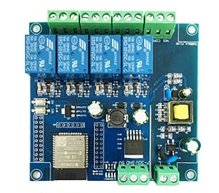
Bild
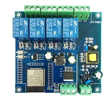
Leiterplatte mit Relaismodul und Mikrocontroller
SRD-05VDC-SL-C, ESP8266
in „Einfachst speicher für BalkonPV“ · Haus & Smart Home · · Platinenfotos
-
PDF
external_photo.pdf
2AC7Z‐ESP8266EX External Photo
in „Wlan2Serial Modul für 5 euro“ · Mikrocontroller und Digitale Elektronik ·
-
Bild
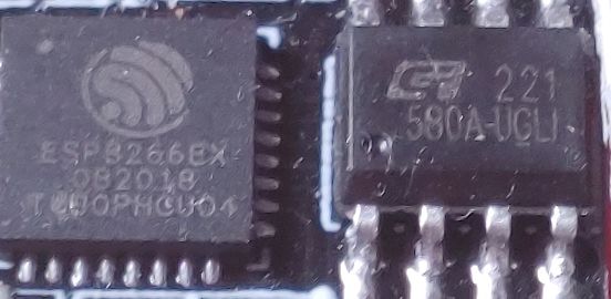
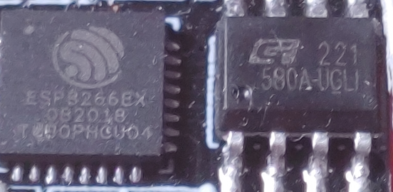
Nahaufnahme von zwei integrierten Schaltkreisen auf einer Platine
ESP8266EX 082018 TCW0PHCU04 221 580A-UGLI
in „ESP01s + deepsleep“ · Mikrocontroller und Digitale Elektronik · · Platinenfotos
-
Bild
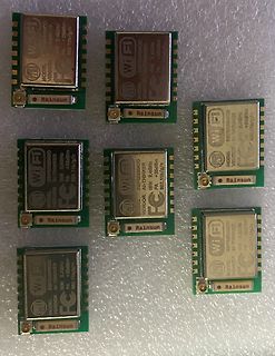
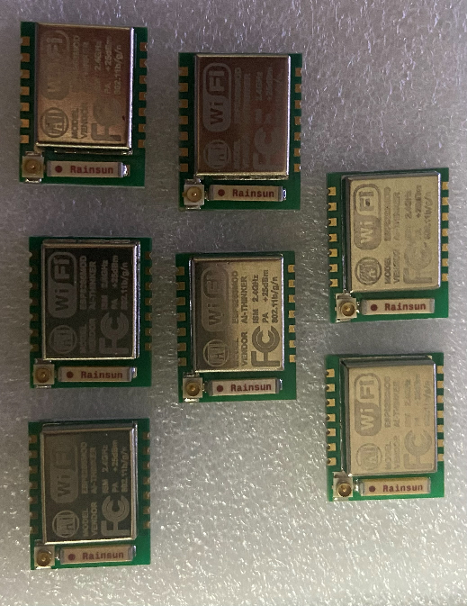
Mehrere Wi-Fi Module von Rainsun
Wi Fi ESP8266MOD 868MHz PA +25dBm 802.11b/g/n VENDOR: Rainsun
in „[V] ESP8266 Module“ · Markt · · Platinenfotos
-
Datei
test3.2.ino
#include <WiFi.h> #include <FirebaseESP32.h> //#include <DHT.h> #include <NTPClient.h> #include <WiFiUdp.h> #include <IRremoteESP8266.h> #include <IRrecv.h> #include <IRutils.h> #define WIFI_SSID "Herech" #define WIFI_PASSWORD "here" #define
in „ESP32 Automatic Reset after one cycle“ · Mikrocontroller und Digitale Elektronik ·
-
Bild
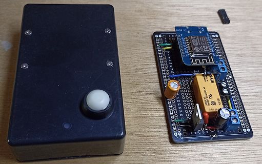
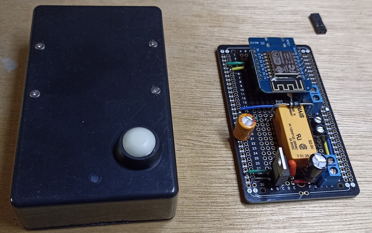
Aufbau mit Mikrocontroller auf Lochrasterplatine und Gehäuse
ESP8266, S2-5V, 4A 120PHE12L, 2 01 28, A B C D E F
in „Softair und elektronische Zielscheibe“ · Mikrocontroller und Digitale Elektronik · · Fotos
-
Bild
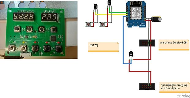
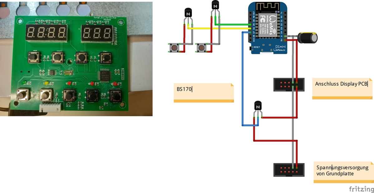
Foto einer Platine und Fritzing-Schaltplan
8.8.8. 8.8.8. D1 mini Wemos LoLin ESP8266 BS170 Anschluss Display PCB Spannungsversorgung von Grundplatte fritzing
in „Saunasteuerung Smart mit Alexa“ · Haus & Smart Home · · Fotos
-
Bild
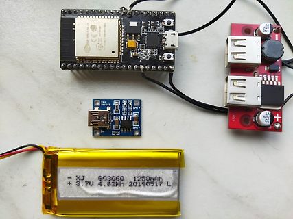
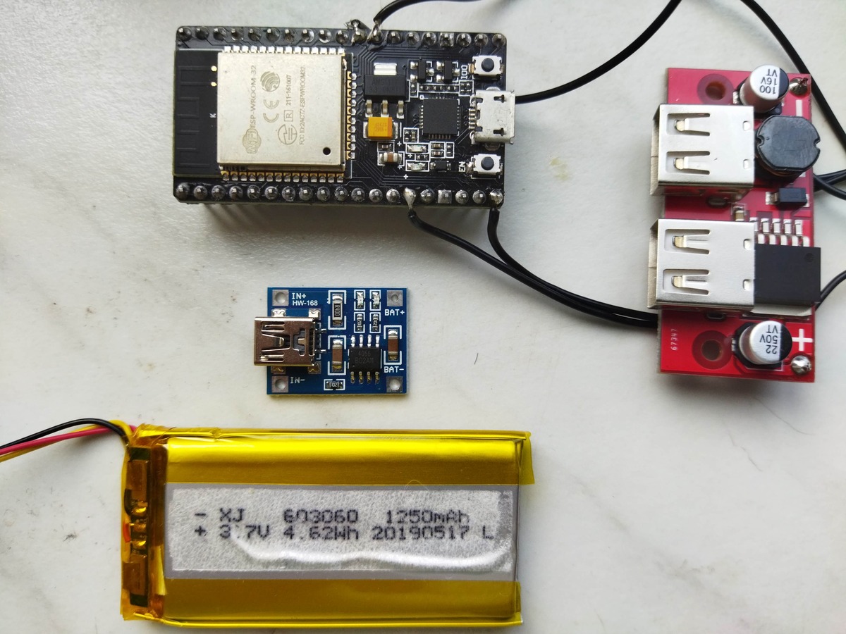
Mikrocontroller, Lademodul, Akku und USB-Verbindung
ESP8266, IN+, IN-, BAT+, BAT-, 16V, 5V, 100, 22, XJ 603060 1250mAh, + 3.7V 4.62Wh 20190517 L
in „nodemcu mit akku betreiben und per Laderegler wieder laden“ · Mikrocontroller und Digitale Elektronik · · Fotos
-
Bild
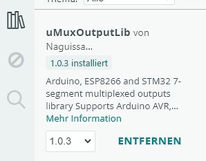
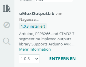
Software-Interface einer installierten Arduino-Bibliothek
uMuxOutputLib von Naguissa... 1.0.3 installiert Arduino, ESP8266 and STM32 7-segment multiplexed outputs library Supports Arduino AVR,... Mehr Information 1.0.3 ENTFERNEN
in „7-Segment LEDs ansteuern“ · Mikrocontroller und Digitale Elektronik · · Screenshots
-
Bild
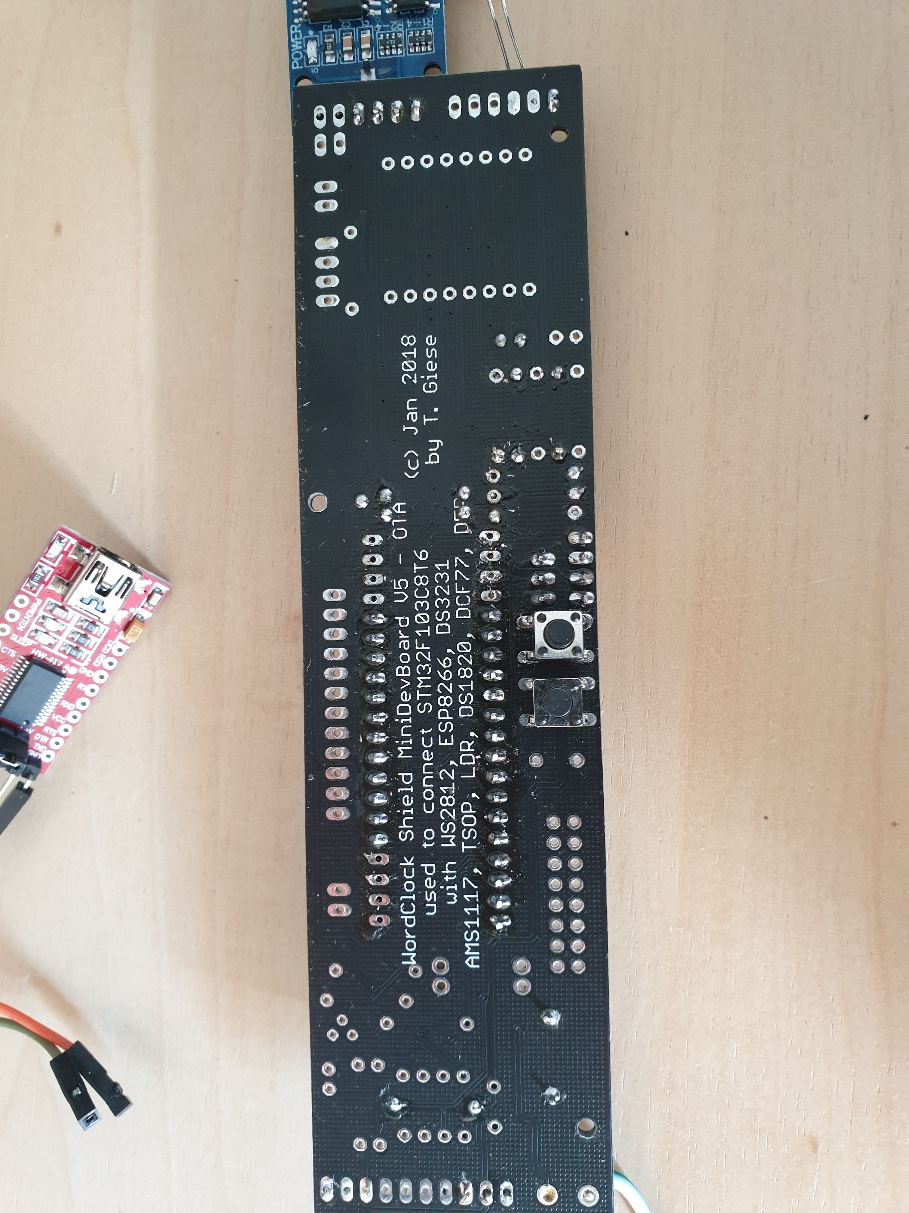
Leiterplatte eines MiniDevBoard Shields
POWER, (c) Jan 2018 by T. Giese, MiniDevBoard V5 - OTA - ESP8266, DS3231, DS28D2, TSOP, LDR, DS1820, AMS1117
in „WordClock mit WS2812“ · Projekte & Code · · Platinenfotos
-
PDF
Test_Setup_Foto.pdf
2AC7Z-ESP8266EX Test Setup photo below 1 GHz Radiated Emission Test Setup Above 1 GHz Radiated Emission Test Setup Conducted Emission Test Setup Zoom in
in „Wlan2Serial Modul für 5 euro“ · Mikrocontroller und Digitale Elektronik ·
-
Bild
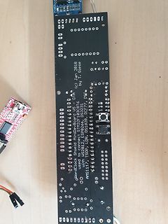
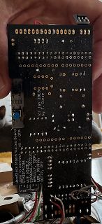
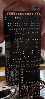
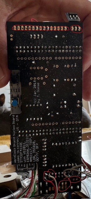
Rückseite einer Leiterplatte mit Beschriftung
(c) Jan 2018 by T. Giese used to connect: Nucleo Board U5 with WS2812B, DS3231, ESP8266, DS18B20, AMS1117, DS1820, DCF77, DFROBOT
in „WordClock mit WS2812“ · Projekte & Code · · Platinenfotos
-
Bild
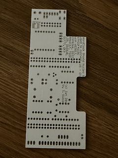
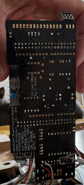
Rückseite einer Hardlock Shield Nucleo Board Leiterplatte
(c) Jan 2018 by T. Giese Hardlock Shield Nucleo Board STM32F411RE with ESP8266, DS3231, AMS1117, TSL2561, LDR, DS18B20, DFPlayer Mini, DCF77
in „WordClock mit WS2812“ · Projekte & Code · · Platinenfotos
-
Bild
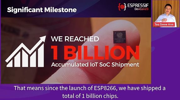
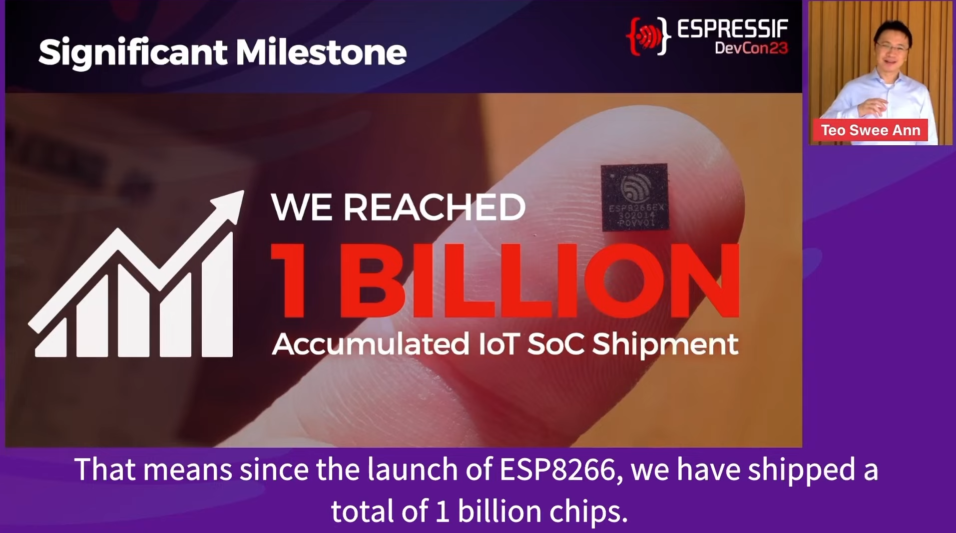
Präsentation von Espressif über 1 Milliarde verkaufte Chips
DevCon23 Teo Swee Ann WE REACHED 1 BILLION Accumulated IoT SoC Shipment That means since the launch of ESP8266, we have shipped a total of 1 billion chips.
in „Espressif DevCon 2023, Tag 1 - Rückkehr des Erfolgskonzepts“ · Mikrocontroller und Digitale Elektronik · · Screenshots
-
Bild
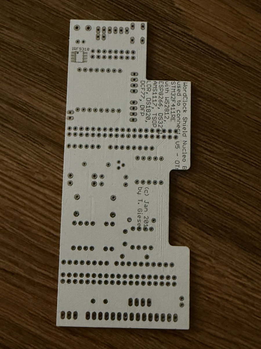
Leiterplatte Nucleo Board Clock Shield
IRF9310 WordClock Shield Nucleo B used to connect ESP8266, DS32 STM32F411RE, DS32 OR, DS1820, DCF77, DS32 U5 - 01 (c) Jan 2016 by T. Giese
in „WordClock mit WS2812“ · Projekte & Code · · Platinenfotos
-
Bild
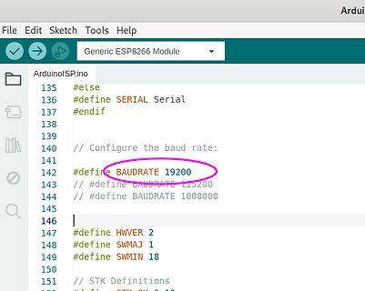
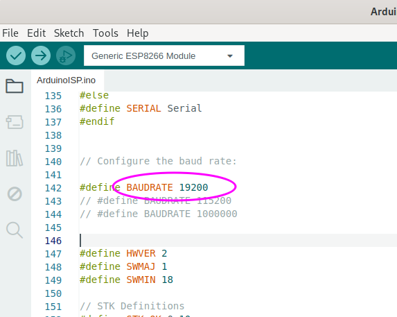
Code-Ausschnitt in der Arduino IDE
File Edit Sketch Tools Help Generic ESP8266 Module ArduinoISP.ino 135 #else 136 #define SERIAL Serial 137 #endif 138 139 // Configure the baud rate: 140 141 #define BAUDRATE 19200 142 // #define BAUDRATE 115200 143 // #define BAUDRATE 1000000
in „Fusebits lassen sich nicht setzen (neuer ATMEGA328P)“ · Mikrocontroller und Digitale Elektronik · · Screenshots
-
PDF
ct-Make_IoT.pdf
KREATIV MIT TEGHNIK CE l( G = tNodeMCU mit Lua programmieren tESP8266 misst GO2 I I Amazons Echo mit Raspberry Pi Funk mit ZigBee tNode-Red steuert Philips Hue tTürklingel vernetzen 11(H17,50 A€10,90 €§§,90 o- für Maker im Uberblick . Einstieg in .-- Funktechniken
-
Bild
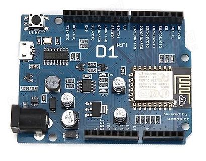
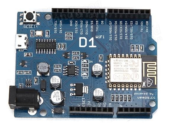
Wemos D1 WiFi Mikrocontroller-Board
MOSI, D11/MOSI/D0, D10/SS, TX1/D9, D8, RX<-D2, D13/SCK/D5, D14/SDA/D4, D15/SCL/D3, D1/D2, D1 WiFi, ESP8266, AI-Thinker, powered by wemos.cc, 47, 10V, 10V, 10V, 35V, RESET, 3.3V, GND, IN
in „Arduino due clone brauchbar?“ · Mikrocontroller und Digitale Elektronik · · Platinenfotos
-
Bild
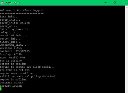
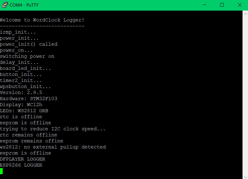
PuTTY Terminal-Ausgabe eines Mikrocontroller-Loggers
offline eeprom remains offline ws2812: no external pullup detected eeprom is offline DFPLAYER LOGGER ESP8266 LOGGER
in „WordClock mit WS2812“ · Projekte & Code · · Screenshots
-
Bild
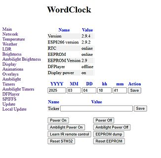
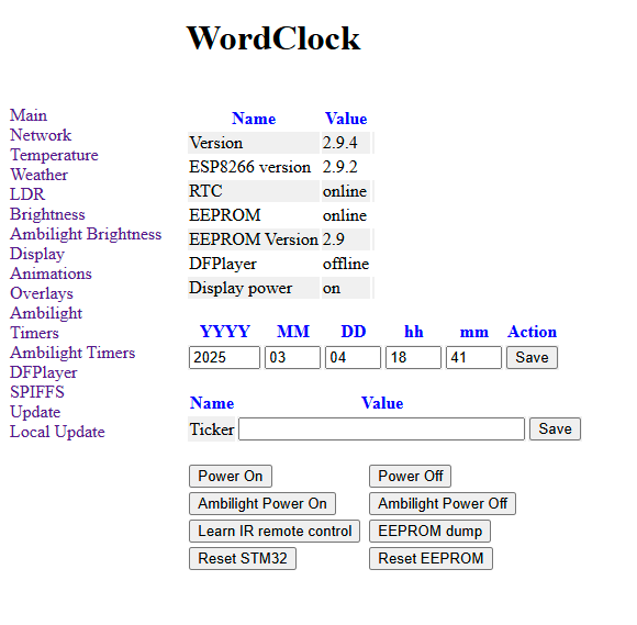
Webinterface einer WordClock Steuerung
WordClock Main Name Value Network Version 2.9.4 Temperature ESP8266 version 2.9.2 Weather RTC online LDR Brightness EEPROM online Ambilight Brightness EEPROM Version 2.9 Display DFPlayer offline Animations Display power on Overlays Ambilight Timers YYYY MM DD hh
in „WordClock mit WS2812“ · Projekte & Code · · Screenshots
-
Bild
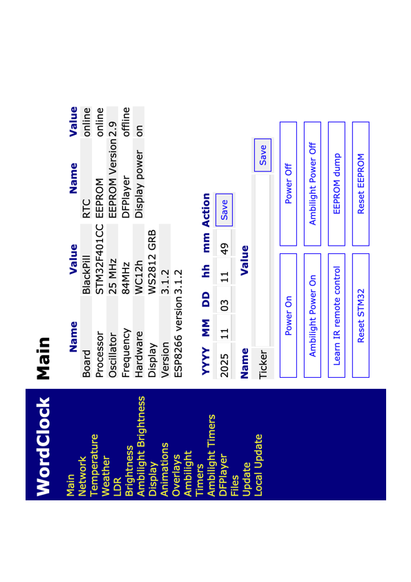
Software-Menü für WordClock Projekt
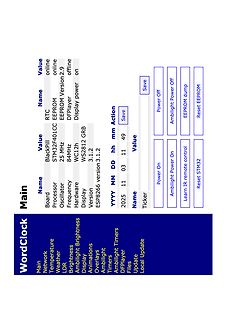
Processor STM32F401CC EEPROM online Oscillator 25 MHz 84MHz Hardware WS2812 GRB Display 3.1.2 Version ESP8266 version 3.1.2 YYYY MM DD hh mm Action 2025 11 03 11 49 Save Ticker Power On Ambilight Power On Learn IR remote control Power Off Ambilight Power Off EEPROM dump Reset STM32 Reset EEPROM
in „WordClock mit WS2812“ · Projekte & Code · · Screenshots
-
Bild
Webinterface einer WordClock mit Systemstatus und Einstellungen
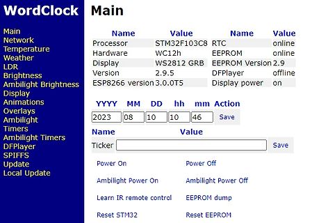
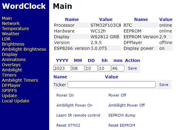
Hardware WC12h EEPROM online Display WS2812 GRB EEPROM Version 2.9 Version 2.9.5 DFPlayer offline ESP8266 version 3.0.0T5 Display power on YYYY MM DD hh mm Action 2023 08 10 10 46 Save Name Value Ticker Save Power On Power Off Ambilight Power On Ambilight Power Off Learn IR remote control EEPROM dump
in „WordClock mit WS2812“ · Projekte & Code · · Screenshots
-
Bild
Terminal-Ausgabe eines ESP32-Flashing-Tools
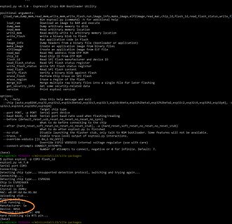
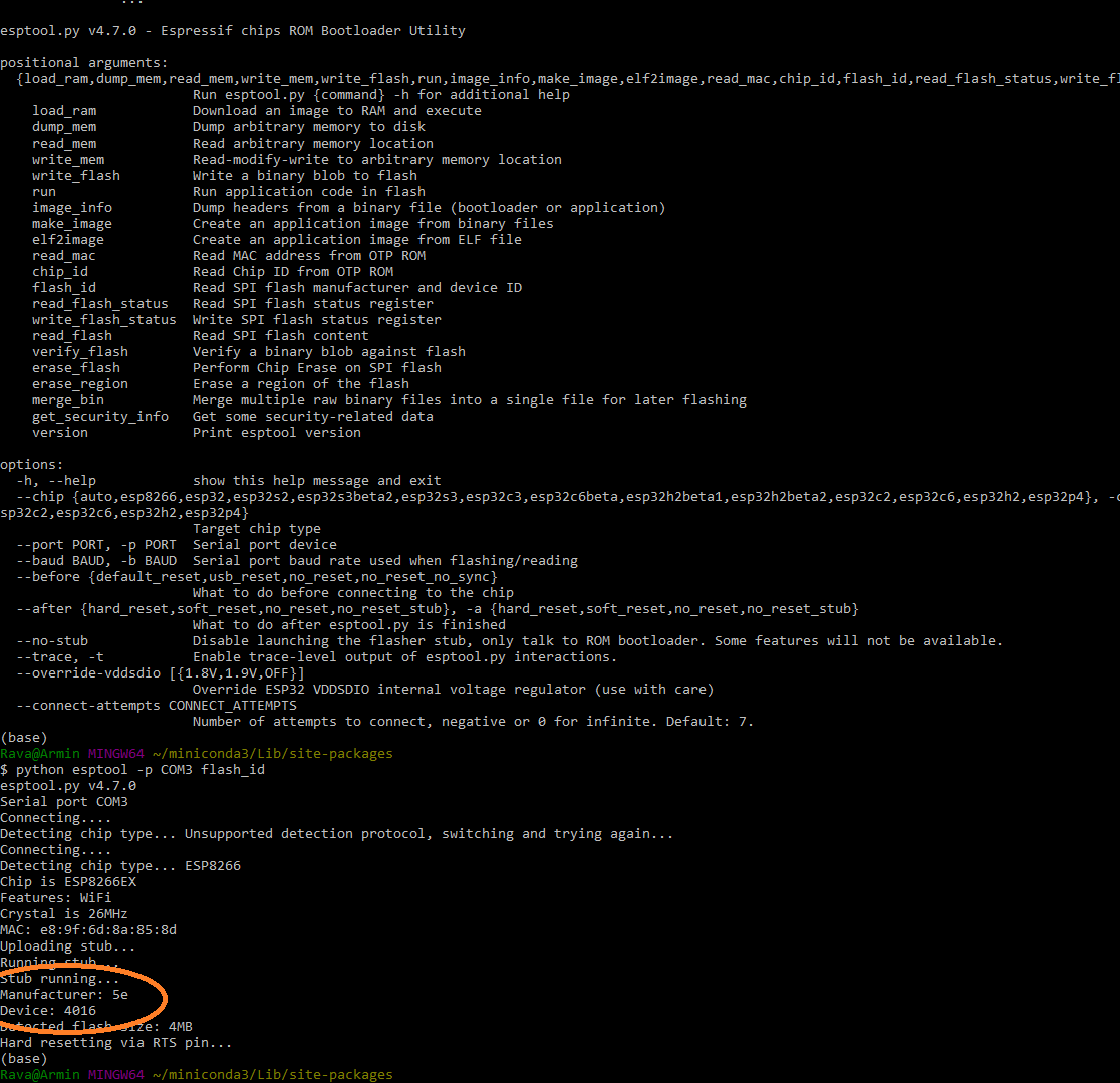
Detecting chip type... Unsupported detection protocol, switching and trying again... Connecting... Chip is ESP8266 Features: WiFi Crystal is 26MHz MAC: e8:9f:6d:8a:85:8d Absorbing stub... Running stub... Stub manufacturer: Espressif Device ID: 0x16 Detected flash size: 4MB Hard resetting via RTS pin...
in „Was ist die Block-Größe meines SPI-ROMs auf dem ESP8266?“ · Mikrocontroller und Digitale Elektronik · · Screenshots
-
Bild
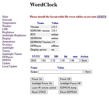
Webinterface einer WordClock Steuerung
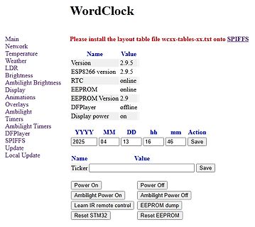
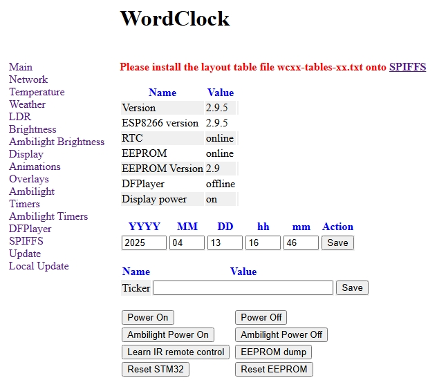
Overlays Ambilight Timers Ambilight Timers DFPlayer SPIFFS Update Local Update Name Value Version 2.9.5 ESP8266 version 2.9.5 RTC online EEPROM online EEPROM Version 2.9 DFPlayer offline Display power on YYYY MM DD hh mm Action 2025 04 13 16 46 Save Name Value Ticker Save Power On Power Off Ambilight Power
in „WordClock mit WS2812“ · Projekte & Code · · Screenshots
-
Bild
Webinterface einer WordClock Steuerung
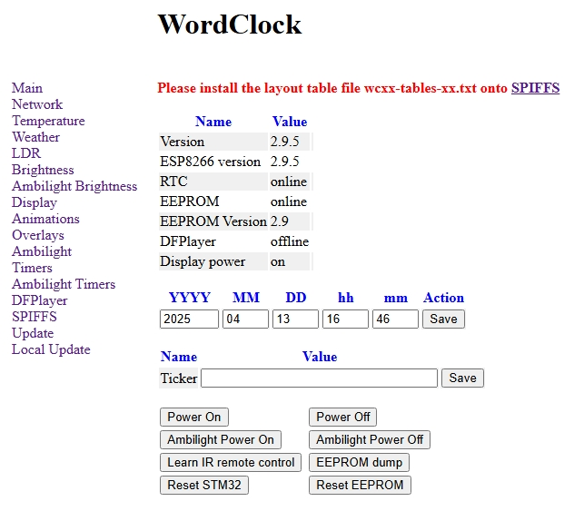
Overlays Ambilight Timers Ambilight Timers DFPlayer SPIFFS Update Local Update Name Value Version 2.9.5 ESP8266 version 2.9.5 RTC online EEPROM online EEPROM Version 2.9 DFPlayer offline Display power on YYYY MM DD hh mm Action 2025 04 13 16 46 Save Name Value Ticker Save Power On Power Off Ambilight Power
in „WordClock mit WS2812“ · Projekte & Code · · Screenshots
-
Bild
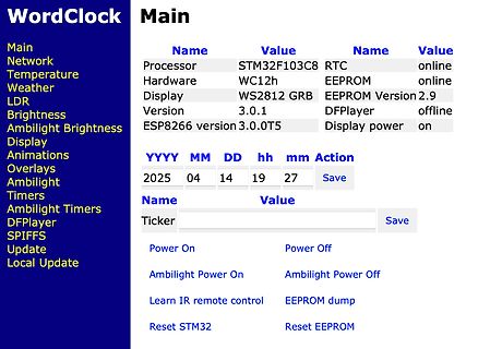
Webinterface einer WordClock Steuerung
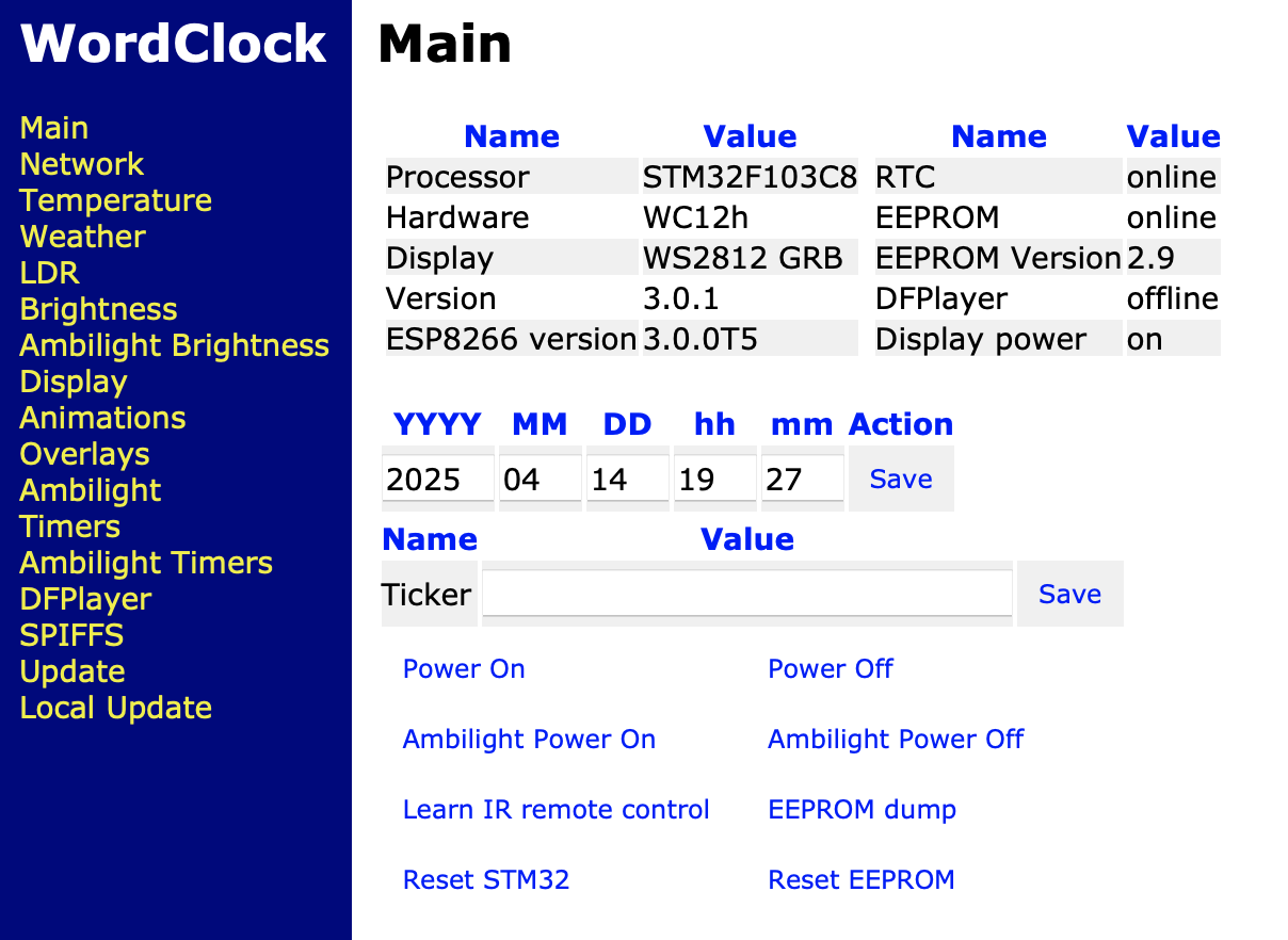
DFPlayer SPIFFS Update Local Update Processor STM32F103C8 Hardware WC12h Display WS2812 GRB Version 3.0.1 ESP8266 version 3.0.0T5 RTC online EEPROM online EEPROM Version 2.9 DFPlayer offline Display power on YYYY MM DD hh mm Action 2025 04 14 19 27 Save Name Value Ticker Save Power On Power Off Ambilight Power
in „WordClock mit WS2812“ · Projekte & Code · · Screenshots
-
Bild
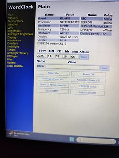
Abfotografierter Bildschirm einer Web-Oberfläche für ein STM32-Projekt
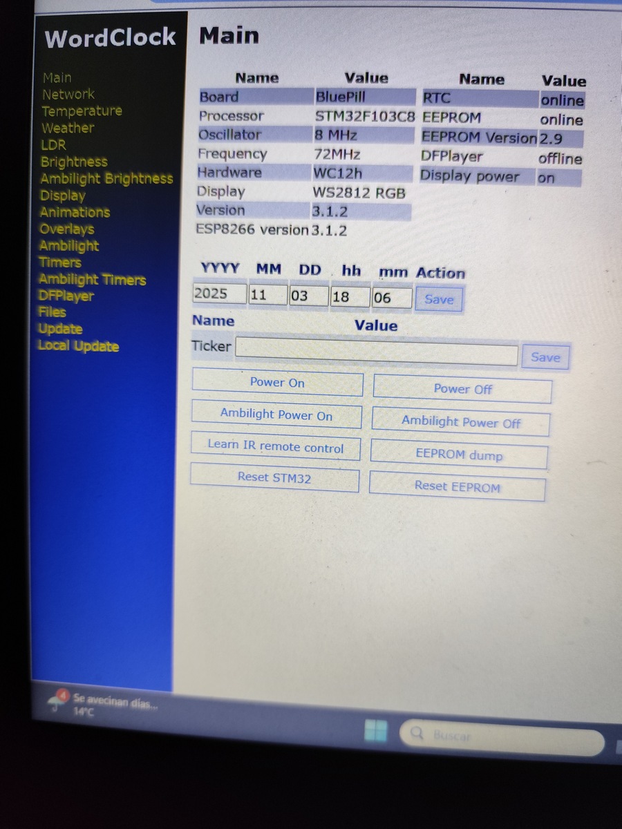
Frequency 72MHz DFPlayer offline Hardware WC12h Display power on Display WS2812 RGB Version 3.1.2 ESP8266 version 3.1.2 YYYY MM DD hh mm Action 2025 11 03 18 06 Save Name Value Ticker Save Power On Power Off Ambilight Power On Ambilight Power Off Learn IR remote control EEPROM dump Reset STM32 Reset
in „WordClock mit WS2812“ · Projekte & Code · · Fotos
-
Datei
log.txt
detected eeprom is online current eeprom version: 0x00020900 reading ir codes from eeprom DFPLAYER LOGGER ESP8266 LOGGER read rtc: Su 2000-01-01 00:00:03 read rtc: Su 2000-01-01 00:00:03 read rtc: Su 2000-01-01 00:00:44 RTC temperature: 24
-
Datei
Wecker.ino
//ESP ADVENTSKALEDER //Biblothecken #include <NTPClient.h> #include <ESP8266WiFi.h> #include <WiFiUdp.h> #include <Kalender.h> //Variablen int buttonPin1 = 1; int buttonPin2 = 2; int buttonPin3 = 3; int buttonPin4
in „Node Mcu WDT Reset“ · Mikrocontroller und Digitale Elektronik ·
-
Bild
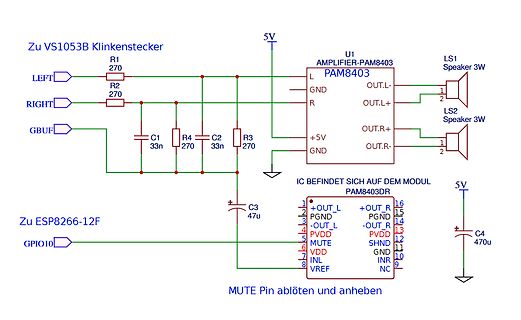
Schaltplan eines PAM8403 Audio-Verstärkers
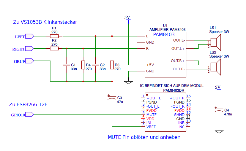
OUT.L- 2 OUT.L+ 1 LS2 Speaker 3W OUT.R+ OUT.R- IC BEFINDET SICH AUF DEM MODUL PAM8403DR C3 47u 5V Zu ESP8266-12F GPIO10 1 +OUT_L 16 +OUT_R 2 PGND 15 PGND 3 -OUT_L 14 -OUT_R 4 PVDD 13 PVDD 5 MUTE 12 SHND 6 VDD 11 GND 7 INL 10 INR 8 VREF 9 NC C4 47u MUTE Pin ablöten und anheben
in „PAM8403 im gleichen Stromkreis wie ESP und VS1053, Rauschen“ · Mikrocontroller und Digitale Elektronik · · Schaltpläne
-
Bild
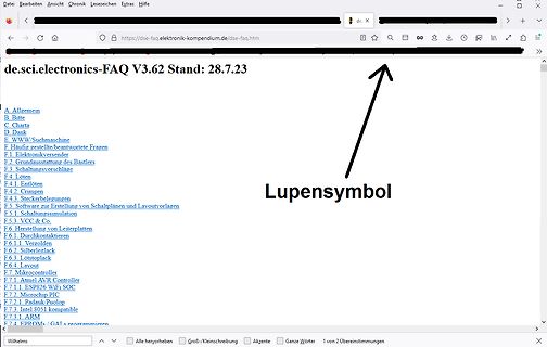
Inhaltsverzeichnis einer Elektronik-FAQ Webseite
Silberleitlack F.6.3. Löstoplack F.6.4. Layout F.7. Mikrocontroller F.7.1. Atmel AVR Controller F.7.1.1. ESP8266 WiFi SoC F.7.2. Microchip PIC F.7.3. Intel 8051 kompatibel F.7.4. ARM F.7.4. EPROMs / GALs programmieren
in „230V auf 220V drosseln“ · Analoge Elektronik und Schaltungstechnik · · Screenshots
-
Bild
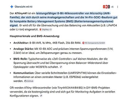
Text über ATtiny441 Mikrocontroller und BMS-Anwendung
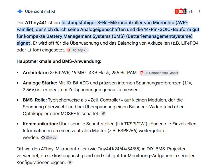
Schnittstellen (UART/SPI/TWI) können die Einzelzellen-Informationen an einen zentralen Master (z.B. ESP8266) weitergeleitet werden. Oft werden ATtiny-Mikrocontroller (wie Tiny441/24/44/84/85) in DIY-BMS-Projekten verwendet, da sie kostengünstig sind und sich gut für Monitoring-Aufgaben in seriellen Konfigurationen
in „alternativ Akku zum verbauten??“ · Analoge Elektronik und Schaltungstechnik · · Screenshots
-
Datei
Logfile.txt
detected eeprom is online current eeprom version: 0x00020900 reading ir codes from eeprom DFPLAYER LOGGER ESP8266 LOGGER read rtc: Su 2000-01-01 18:41:19 read rtc: Su 2000-01-01 18:41:19 net_time_countdown = 3786, don't check overlays read rtc: Su 2000-01-01 18:41:44 RTC temperature: 23 Welcome to WordClock
-
Datei
ESPNow2Serial_micropython.py
send()/recv() sta = network.WLAN(network.WLAN.IF_STA) sta.active(True) sta.disconnect() # Because ESP8266 auto-connects to last Access Point print('MAC:', ':'.join(['%02x' % b for b in sta.config('mac')])) e = espnow.ESPNow() e.active(True) print("timestamp, temperature, pressure, humidity, vbat, counter
-
Datei
tcptest.ino
#include <ESP8266WiFi.h> #include <WiFiClient.h> const char* ssid = "WLAN"; const char* password = "PASSWORT"; const int serverport = 4210; WiFiServer server(serverport); void setup() { Serial.begin(115200); Serial.println
in „ESP8266 TCP Server: Erster Verbindungsaufbau nach Reset dauert lange“ · Mikrocontroller und Digitale Elektronik ·
-
Bild
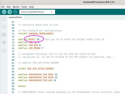
Arduino IDE Code-Ausschnitt ArduinoISP
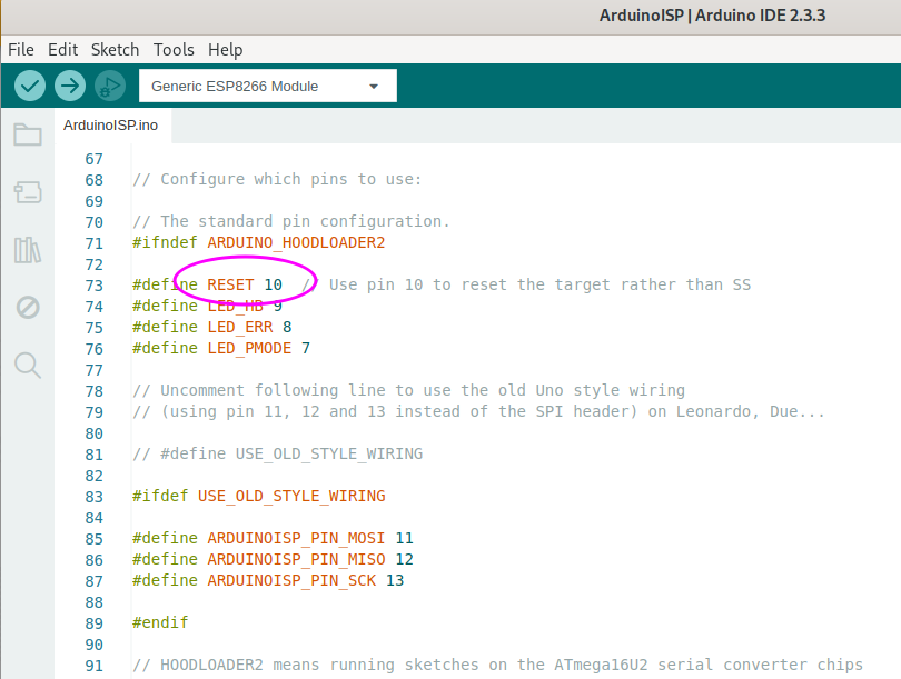
ArduinoISP | Arduino IDE 2.3.3 File Edit Sketch Tools Help Generic ESP8266 Module ArduinoISP.ino 67 68 // Configure which pins to use: 69 70 // The standard pin configuration. 71 #ifndef ARDUINO_HOODLOADER2 72 73 #define RESET 10 // Use pin 10 to reset the target rather

in „Fusebits lassen sich nicht setzen (neuer ATMEGA328P)“ · Mikrocontroller und Digitale Elektronik · · Screenshots