-
Datei
main.c
syncstat == 31) { //fertig dt = ICR1; //Sollwert 6660 @ 1MHz if ( (dt > 5994) && (dt < 7326) ) { //Max. Abweichung +-10% //OSCCAL = } TCCR1B = 0x00; //deaktivieren TIMSK1 = 0x00 ; //deaktivieren syncstat = 128; //fertig } PORTD &= ~(1<< PD7); } ISR(TIMER1_OVF_vect) { //Darf nie aufgerufen werden -> Fehler
in „AVR probleme ICP interrupt“ · Mikrocontroller und Digitale Elektronik ·
-
Datei
eeprom.c
(optimize(0))) e2p_PageWrite(uint8_t *source, uint16_t target, uint16_t count) { #define BLOCKSIZE 128 // je 128 Bytes wegschreiben if (!I2C3_initialized) { Init_I2C3(); I2C3_initialized = true; } // Ist Zieladresse eine Pageadresse? if (target % 128 != 0) return ERROR; // Berechne die 64 Byte Blöcke
in „STM32F4xx: 24LC512 EEPROM Zugriffsroutinen“ · Projekte & Code ·
-
Datei
eeprom.c
(optimize(0))) e2p_PageWrite(uint8_t *source, uint16_t target, uint16_t count) { #define BLOCKSIZE 128 // je 128 Bytes wegschreiben if (!I2C_initialized) { e2p_Init_I2C(I2C_CHANNEL); I2C_initialized = true; } // ACK ein I2C_AcknowledgeConfig(I2C_CHANNEL, ENABLE); // Ist Zieladresse eine Pageadresse?
in „Organisation der Header und Includes“ · Mikrocontroller und Digitale Elektronik ·
-
PDF
SLR2016.PDF
.....................75 cd/LED min.forms LED to LED Intensity Matching, VCC=5 V............1.8:1.0 max. Viewing Angle (off normal axis) A0 – A1 2.0 V Horizontal ....................................50 max................. 0.8 V TAS TAH Vertical . ............................................................. 75° max. Note 1: Peak luminous intensity values can be calculated by D0 – D6 2.0 V multiplying these values by 7. 0.8 V TDS TDH WR DC Characteristics at 25°C 0.8 V Parameter Min. Typ. Max. Units Condition TW
-
PDF
Blockdiagramm.pdf
595 CH340 UART0 PB7:0 8-bit DIP PG1 UART1 Atmega328 PD3 Heartbeat Heartbeat AREF PC7:0 PF0 LCD Atmega128 DRV5033 PA7:0 I²C MAX520 Pinheader LM4040 + Buffer WS2812 PG0 PB7:0 CAT5259 PG4 ADS7828 RV4162 Backup Battery ICSP M24C64 JTAG PF7:0 AREF PG4 RS232/UART UART0 I²C MAX520 LM4040 + MAX3232 Buffer Atmega128L
in „Dev-Kit machen?“ · Mikrocontroller und Digitale Elektronik ·
-
PDF
PH128128C-024-LY1Q.pdf
NT7571 PH128128C-024-LY1Q Ver.0 Page3 1. SPECIFICATIONS 1.1 Features Item Standard Value Display Type 128 *(R¡B G¡B ) * 128 Dots LCD Type CSTN¡A Negative¡A Transmissive Driver Condition LCD Module : 1/132 Duty , 1/6 Bias Screen size(inch) 1.5 (Diagonal) Viewing Direction 12 O’clock Color configuration R.G.B
in „[V]Color LCD CSTN 2.4" 128xR'G'B'x128 Typ PH128128C-024-L“ · Markt ·
-
PDF
3200.pdf
SY203 Platine Transistoren T1 Si-NPN-Leistungstransistor TO-3 KU607 Kühlkörper T2 Si-NPN-Transistor SF128D Platine BSY55 T3 Si-NPN-Transistor SF128D Platine BSY55 T4 Si-NPN-Transistor SF128D Platine BSY55 T5 Si-NPN-Transistor SF128D Platine BSY55 Sicherungen Si1 Schmelzsicherung 5 mm x 20 mm 0,2 A träge
in „Gefundene neue Serviceanleitung Statron 3200“ · Offtopic ·
-
Datei
sip_klingel_ND.ino
*SipIp, int SipPort, const char *MyIp, int MyPort, const char *SipUser, const char *SipPassWd, int MaxDialSec) { caRead[0] = 0; pbuf[0] = 0; pSipIp = SipIp; iSipPort = SipPort; pSipUser = SipUser; pSipPassWd = SipPassWd; pMyIp = MyIp; iMyPort = MyPort; iAuthCnt = 0; iRingTime = 0; iMaxTime = MaxDialSec
-
Datei
Sipdial_esp32.ino
*SipIp, int SipPort, const char *MyIp, int MyPort, const char *SipUser, const char *SipPassWd, int MaxDialSec) { caRead[0]=0; pbuf[0]=0; pSipIp=SipIp; iSipPort=SipPort; pSipUser=SipUser; pSipPassWd=SipPassWd; pMyIp=MyIp; iMyPort=MyPort; iAuthCnt=0; iRingTime=0; iMaxTime=MaxDialSec*1000; } void Sip::AddSipLine
-
Datei
sipdial.ino
*SipIp, int SipPort, const char *MyIp, int MyPort, const char *SipUser, const char *SipPassWd, int MaxDialSec) { caRead[0]=0; pbuf[0]=0; pSipIp=SipIp; iSipPort=SipPort; pSipUser=SipUser; pSipPassWd=SipPassWd; pMyIp=MyIp; iMyPort=MyPort; iAuthCnt=0; iRingTime=0; iMaxTime=MaxDialSec*1000; } void Sip::AddSipLine
-
PDF
DOG_readme.pdf
Grafische Darstellungen auf dem Display DOG 128x64 Nach dem Motto " Es ist zwar schon alles gesagt, aber noch nicht von jedem" will ich hier meinen Exkurs in das Thema "Grafische Darstellungen auf den Display DOG128x64" beisteuern. Beim Einstieg
in „Grafikausgabe auf dem LCD-Grafikmodul DOG 128x64 für M88 in C“ · Projekte & Code ·
-
Datei
sdkconfig.h
CONFIG_LWIP_DHCP_DISABLE_VENDOR_CLASS_ID 1 #define CONFIG_LWIP_DHCP_RESTORE_LAST_IP 1 #define CONFIG_LWIP_DHCP_OPTIONS_LEN 128 #define CONFIG_LWIP_DHCPS 1 #define CONFIG_LWIP_DHCPS_LEASE_UNIT 60 #define CONFIG_LWIP_DHCPS_MAX_STATION_NUM 8 #define CONFIG_LWIP_IPV6 1 #define CONFIG_LWIP_IPV6_AUTOCONFIG 1 #define CONFIG_LWIP_IPV6
in „ESP32 sdkconfig.h ändern, bloss wie?“ · Mikrocontroller und Digitale Elektronik ·
-
PDF
UC1698u_Revision__1.5.pdf
under 17.5V at -40 C. e i d f o n C p i h c r a l t U 54 U LTRA C HIP UC1698u_C 1.5 ©1999 ~ 2014 160x128RGB CSTN Controller-Driver S PECIFICATIONS DC C HARACTERISTICS Symbol Parameter Conditions Min. Typ. Max. Unit VDD Supply for digital circuit 1.65 3.465 V VDD2/3 Supply for bias & pump 2.7 3.465 V V
in „Defekte Heizungsregelung RC310 Display leuchtet“ · Haus & Smart Home ·
-
Datei
twitest.c
* * Compatibility defines. This should work on ATmega8, ATmega16, * ATmega163, ATmega323 and ATmega128 (IOW: on all devices that * provide a builtin TWI interface). * On the 128, it defaults to USART 1. */ #ifndef UCSRB # ifdef UCSR1A /* ATmega128 */ # define UCSRA UCSR1A # define UCSRB UCSR1B # define
in „I2C-Bus und DS1631“ · Mikrocontroller und Digitale Elektronik ·
-
Datei
wiring.c
m = timer0_millis; unsigned char f = timer0_fract; m += MILLIS_INC; f += FRACT_INC; if (f >= FRACT_MAX) { f -= FRACT_MAX; m += 1; } timer0_fract = f; timer0_millis = m; timer0_overflow_count++; } unsigned long millis() { unsigned long m; uint8_t oldSREG = SREG; // disable interrupts while we read timer0
in „IRMP - Infrared Multi Protocol Decoder“ · Projekte & Code ·
-
Datei
fitsinus2.m
sp3=fft(sigsoll(1 : nn)); sp2=fft(sigsoll(1+d:nn+d).*wind); %plot(20*log10(abs(sp1)),'.-') [m,ind] = max(abs(sp1(1:length(sp1)/2))); %angle(sp1(ind)) dw=angle(sp2(ind)/sp1(ind)); %wb=ff/2*2*pi/512 fg=(dw/d/(2*pi)) %ff-fg sp=fft(cos(2*nn*fg*pi*(0:nn-1)/nn).*wind); % Amplitude considerations % Das Ganze
in „Wie nach DFT/FFT die Signalfrequenz bestimmen?“ · Digitale Signalverarbeitung / DSP / Machine Learning ·
-
PDF
DLO2416.pdf
.031 .250 .136 .260 (.79) (6.35) (3.45) (6.60) ref. (.79) .800 .600 .020 (20.32) (15.24 .51) .198 max. (5.03) .1.00 max. .012 (.30) (25.4) .002 (.05) .Pin 1Part No. 18 pl. Indicator EIA Date Code .070 (1.78) .003 (.08) .010 (.25) 8 pl. (1.27) pl. DLX2416 Z SIEMENS YYWW .260 (6.60) FEATURES .160 .020
-
PDF
EA_W128128-XR.pdf
82205 GilchingFon +49-8105-778090 info@lcd-module.dehttp://www.lcd-module.de 5.2018 Round OLED 37mm - 128x128 dots Incl. controller SSD1327ZB Features 1.2” Low-Power OLED -40..+80°C (Top.) 128x128 dots Incl. controller SSD1327ZB SPI, I²C, 8-Bit Interface Fast response time (10µs) even at -40°C ZIFF connection 37mm diameter Ordering code OLED 1.2” - 128x128 dots, round yellow EA W128128-XRLG OLED 1.2” - 128x128 dots, round white EA W128128-XRLW OLED 1.2” - 128x128 dots, round blue EA W128128-XRLB Accessory ZIFF connector 24 pins, 0.5mm pitch, bottom
in „OLED-Display SPI Psoc4“ · Mikrocontroller und Digitale Elektronik ·
-
PDF
EAW128128-XRLW.pdf
82205 GilchingFon +49-8105-778090 info@lcd-module.dehttp://www.lcd-module.de 5.2019 Round OLED 37mm - 128x128 dots Incl. controller SSD1327ZB Features 1.2” Low-Power OLED -40..+80°C (Top.) 128x128 dots Incl. controller SSD1327ZB SPI, I²C, 8-Bit Interface Fast response time (10µs) even at -40°C ZIFF connection 37mm diameter Ordering code OLED 1.2” - 128x128 dots, round yellow EA W128128-XRLG OLED 1.2” - 128x128 dots, round white EA W128128-XRLW OLED 1.2” - 128x128 dots, round blue EA W128128-XRLB Accessory ZIFF connector 24 pins, 0.5mm pitch, bottom
in „[V] 2x EA W128128-XRLW OLED-Display, rund, weiß“ · Markt ·
-
PDF
AT24C01A_02_04_08_16__2001_.pdf
, 8K, 16K) Write Modes Serial EEPROM Partial Page Writes are Allowed Self-timed Write Cycle (10 ms max) 1K (128 x 8) High-reliability – Endurance: 1 Million Write Cycles 2K (256 x 8) – Data Retention: 100 Years Automotive Grade and Extended Temperature Devices Available 4K (512 x 8) 8-lead JEDEC SOIC
-
PDF
STM32_DS1307.pdf
DS1307 – 24C128 – DS18B20 – Module We are only interested in RTC-chip DS1307. We do not use memory chip 24C128 and digital thermometer IC DS18B20, and we do not use any battery on the back side of the module. We only
in „I2C STM32F103“ · Mikrocontroller und Digitale Elektronik ·
-
Datei
OLED_2_42_SSD1309_test_igel1_v006e.ino
= -1" => shift min-bound left } else if (pulseLength > pulseLengthMax) { // pulseLength > max pulseLengthMax++; direction = 1; // "direction = +1" => shift max-bound right } else if ((pulseLength == pulseLengthMin) || (pulseLength == pulseLengthMax)) { // pulseLength
in „Induktiver Positionssensor - Fragen dazu“ · Mikrocontroller und Digitale Elektronik ·
-
PDF
treibhaus_mikroforum_0511.pdf
Lux, Maßstab 1 : 40 Lage der Fläche im Raum: Markierter Punkt: (0.000 m, 0.000 m, 0.500 m) Raster: 128 x 64 Punkte Em[lx] Emin [lx] E max[lx] g1 g2 1214 151 2327 0.124 0.065 Seite 7 Projekt 1 15.05.2011 Bearbeiter(in) Telefon Fax e-Mail Raum 1 / 1 / Isolinien (E, senkrecht) 500 500 2.50m 500 500 1000
in „Tip f. Sensorik b. Höhenanpassung von Leuchten ges.“ · Mikrocontroller und Digitale Elektronik ·
-
PDF
GT30L24A3W_V1.0I_C.PDF
Standard W ASCII 6x12 96 Standard W ASCII 6x12Sspread 32 Standard W ASCII 8x16 96 Bold W ASCII 8X16spread 128 Standard W ASCII ASCII 12X24spread 128 Standard W ASCII 12x24 224 Print Font W ASCII 16x32C 96 Bold W ASCII 12dotA 96 Rounded font W ASCII 16dotA 96 Rounded font W ASCII 24dotA 96 Rounded font W ASCII
in „Suche Info's zum Fontspeicher GT30L24A3W“ · Mikrocontroller und Digitale Elektronik ·
-
PDF
WG320240BX-TFHVZ_021__1.pdf
putting it in a container. Page 3 of 25 11. Backlight Information (Ta=25℃) PARAMETER SYMBOL MIN TYP MAX UNIT TEST CONDITION Supply CurrentILED 115.2 128 200 mA V=3.5V Supply VoltageV 3.4 3.5 3.6 V - Reverse VoltagVR - - 5 V - Luminous IV 260 280 - CD/M 2 ILED=128mA Intensity Wave Length λp ─ - - nm ILED
in „[V] 8 LCDs 320x240 s/w, 6 Zoll, Touch, inkl Controller“ · Markt ·
-
PDF
WG320240BX-TFHVZ_021__1.pdf
putting it in a container. Page 3 of 25 11. Backlight Information (Ta=25℃) PARAMETER SYMBOL MIN TYP MAX UNIT TEST CONDITION Supply CurrentILED 115.2 128 200 mA V=3.5V Supply VoltageV 3.4 3.5 3.6 V - Reverse VoltagVR - - 5 V - Luminous IV 260 280 - CD/M 2 ILED=128mA Intensity Wave Length λp ─ - - nm ILED
in „[v] LCDs 320x240 s/w, 6 Zoll, Touch, inkl Controller“ · Markt ·
-
PDF
WG320240BX-TFHVZ_021__1_320-240_display.pdf
putting it in a container. Page 3 of 25 11. Backlight Information (Ta=25℃) PARAMETER SYMBOL MIN TYP MAX UNIT TEST CONDITION Supply CurrentILED 115.2 128 200 mA V=3.5V Supply VoltageV 3.4 3.5 3.6 V - Reverse VoltagVR - - 5 V - Luminous IV 260 280 - CD/M 2 ILED=128mA Intensity Wave Length λp ─ - - nm ILED
in „Anstuerung eines Grafik LCDs. Fragen zu Display und Controller“ · Mikrocontroller und Digitale Elektronik ·
-
PDF
208_945-15.pdf
100 mm × 65 mm 35 Inkrementalsignale » 1 V SS Die sinusförmigen Inkrementalsignale A MT 128x, MT 258x, ST 128x, ST 308x und B sind um 90° el. phasenverschoben und haben einen Signalpegel von typ. Ausgangsignale sinusförmige Spannungssignale » 1 V SS 1 VSS Der Nutzanteil des Referenzmar- Inkremental
in „Welchen Mikrocontroller Quadrature Decoder Kanäle ?“ · Mikrocontroller und Digitale Elektronik ·
-
PDF
208_945-15.pdf
100 mm × 65 mm 35 Inkrementalsignale » 1 V SS Die sinusförmigen Inkrementalsignale A MT 128x, MT 258x, ST 128x, ST 308x und B sind um 90° el. phasenverschoben und haben einen Signalpegel von typ. Ausgangsignale sinusförmige Spannungssignale » 1 V SS 1 VSS Der Nutzanteil des Referenzmar- Inkremental
in „Wie entsteht das Sinusförmige Signal eines Drehgebers/ Vermutung“ · Offtopic ·
-
PDF
208_945-15.pdf
100 mm × 65 mm 35 Inkrementalsignale » 1 V SS Die sinusförmigen Inkrementalsignale A MT 128x, MT 258x, ST 128x, ST 308x und B sind um 90° el. phasenverschoben und haben einen Signalpegel von typ. Ausgangsignale sinusförmige Spannungssignale » 1 V SS 1 VSS Der Nutzanteil des Referenzmar- Inkremental
in „SIN/COS Encoder“ · Analoge Elektronik und Schaltungstechnik ·
-
PDF
SC51P66E04_Datasheet_1.20190628115453636973.pdf
HIGH-PRECISION PWM SUPPORTED ADC MCU DESCRIPTION SC51P66E04 adopts SC51 core with built-in 4Kbyte OTP, 128 byte RAM 2 and 256 byte E PROM. It integrates one 16MHz high-precision RCK, one 6-channel 12-bit precision ADC, one universal pulse generator, supporting 2-channel complementary PWM output and it suitable
in „Welche IC's / Funktion Mittelabgriff Akkupack ?“ · Analoge Elektronik und Schaltungstechnik ·
-
Datei
pmx_specs.txt
. RESOLUTION - up to 14 bits, but normally 8 bits (256 possibilities), older products used 7 bits (128 possibilities). NO OF CHANNELS - 15,360 max. - the protocol allows 128 pages of 120 channels each - for future expansion! REFRESH - not required. Data is latched by the receiving device. Only the changes
in „Probleme bei DMX512-Signalerzeugung“ · Mikrocontroller und Digitale Elektronik ·
-
Datei
eeprom.c
------ uint8_t e2p_PageWrite(uint8_t *source, uint16_t target, uint16_t count) { #define BLOCKSIZE 128 // je 128 Bytes wegschreiben if (!I2C_initialized) { e2p_Init_I2C(I2C_CHANNEL); I2C_initialized = true; } // ACK ein I2C_AcknowledgeConfig(I2C_CHANNEL, ENABLE); // Ist Zieladresse eine Pageadresse?
in „GCC Optimierung killt Funktion“ · Mikrocontroller und Digitale Elektronik ·
-
Datei
mso5202d.txt
0x000008000000 : "ROOTFS" UBI: attaching mtd3 to ubi0 UBI: physical eraseblock size: 131072 bytes (128 KiB) UBI: logical eraseblock size: 126976 bytes UBI: smallest flash I/O unit: 2048 UBI: VID header offset: 2048 (aligned 2048) UBI: data offset: 4096 UBI: max. sequence number: 777 UBI: attached mtd3
in „Tekway/Hantek/Voltcraft MSO“ · Mikrocontroller und Digitale Elektronik ·
-
 Bild
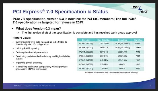
PCI Express 7.0 Spezifikation und Status Übersicht
efficiency Maintaining backwards compatibility with all previous generations of PCIe technology Revision Max Data Rate Encoding Signaling PCIe 7.0 (2025) 128.0 GT/s 1b/1b (Flit Mode*) PAM4 PCIe 6.0 (2022) 64.0 GT/s 1b/1b (Flit Mode*) PAM4 PCIe 5.0 (2019) 32.0 GT/s 128b/130b NRZ PCIe 4.0 (2017) 16.0 GT/s 128b/130b NRZ PCIe 3.0 (2010) 8.0 GT/s 128b/130b NRZ PCIe 2.0 (2007) 5.0 GT/s 8b/10b NRZ PCIe 1.0 (2003) 2.5 GT/s 8b/10b NRZ *Flit Mode also enabled in other Data Rate with their respective encoding
in „Neue PC-Standards, Exportbeschränkungen, Funkmodule und Messtechnik“ · Mikrocontroller und Digitale Elektronik · · Screenshots
-
Datei
main.c
Riegel (www.roland-riegel.de) // - SHT75 Brian Low (mportobello@hotmail.com) / Daniel Buergin // - MAX7219 Code Daniel Buergin // - Debounce Routinen von Peter Dannegger // //===================================================================================== // // HW: - ATmega128 Board von www.futurlec.com
in „Tempertur/Feuchte Display/Logger mit ATMega128 / SHT75 / SD-Karte“ · Projekte & Code ·
-
 Bild
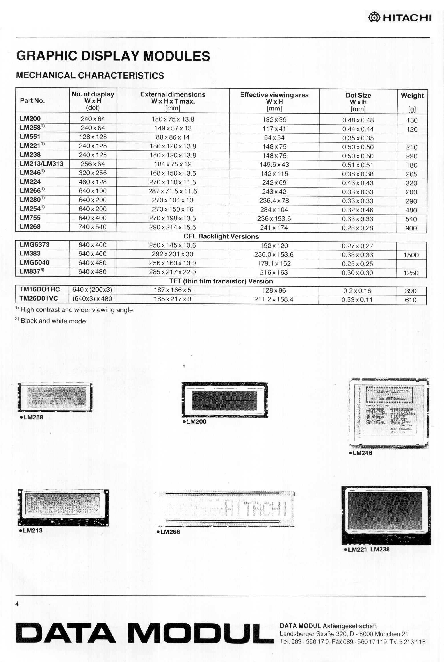
Tabelle mit technischen Daten von Hitachi Display Modulen
DISPLAY MODULES MECHANICAL CHARACTERISTICS Part No. No. of display W x H (dot) External dimensions W x H max. [mm] Effective viewing area W x H [mm] Dot Size W x H [mm] Weight [g] LM200 240 x 64 180 x 75 x 13.5 132 x 39 0.48 x 0.38 150 LM258 240 x 64 149 x 57 x 13.5 117 x 41 0.44 x 0.44 120 LM551 128 x 128 88 x 86 x 14 54 x 54 0.35 x 0.35 LM221 240 x 128 180 x 120 x 13.8 148 x 75 0.50 x 0.50 210 LM213/LM313 240 x 128 180 x 120 x 13.8 148 x 75 0.50 x 0.50 220 LM246 320 x 256 270 x 198 x 13.5 142 x 115 0.51 x 0.38 265 LM266 480 x 128 270 x 110 x 11.5
in „SML02 streifiges Display tauschen“ · HF, Funk und Felder · · Screenshots
-
Datei
dmesg.txt
successfully opened [ 127.735040] /dev/vmmon[2696]: PTSC: initialized at 2671825000 Hz using TSC [ 128.285828] /dev/vmnet: open called by PID 2701 (vmware-vmx) [ 128.285846] /dev/vmnet: port on hub 3 successfully opened [ 128.286348] /dev/vmnet: open called by PID 2701 (vmware-vmx) [ 128.286359] device eth0 entered promiscuous mode [ 128.286366] bridge-eth0: enabled promiscuous mode [ 128.286368] /dev/vmnet: port on hub 0 successfully opened [ 128.286843] /dev/vmnet: open called by PID 2701 (vmware-vmx) [ 128.286852] device eth1 entered
in „Sporadische Gnome-Abbrüche auf Ubuntu 10.04“ · PC Hard- und Software ·
-
Datei
LED_Laufschrift9.asm
mov dpth,r0 mov r1,#0 mov r3,#0 ret ;Rücksprung aus UP ;*********Datenübergabe an die Laufschrift max_out: push acc push 0 CLR MAX_LOAD MOV A,#10000000b MOV R0,A adresse: ANL A,MAX_ADRESSE CLR MAX_DIN jz adresse31 SETB MAX_DIN adresse31: SETB MAX_CLOCK CLR MAX_CLOCK MOV A,R0 RR A MOV R0,A cjne A,#128,adresse MOV R0,A daten: ANL A,MAX_DATEN CLR MAX_DIN jz daten2 SETB MAX_DIN daten2: SETB MAX_CLOCK CLR MAX_CLOCK MOV A,R0 RR A MOV R0,A cjne A,#128,daten pop 0 pop acc ret ;*********Auswahl des richtigen Moduls out: mov a,r3 leer: cjne
in „Probleme mit Hardware Handshake“ · Mikrocontroller und Digitale Elektronik ·
-
Datei
0001-Visual-Studio-2015-Files.patch
_MAX INT64_MAX -#define UINT_LEAST8_MAX UINT8_MAX -#define UINT_LEAST16_MAX UINT16_MAX -#define UINT_LEAST32_MAX UINT32_MAX -#define UINT_LEAST64_MAX UINT64_MAX - -// 7.18.2.3 Limits of fastest minimum-width
in „Simulavr unter Windows mit Visual Studio 2015 kompilieren“ · Mikrocontroller und Digitale Elektronik ·
-
Datei
erase.txt
Memory Detail : Block Poll Page Polled Memory Type Mode Delay Size Indx Paged Size Size #Pages MinW Max W ReadBack ----------- ---- ----- ----- ---- ------ ------ ---- ------ ----- --- -- --------- eeprom 4 12 64 0 no 4096 8 0 9000 90 00 0xff 0xff flash 33 6 128 0 yes 131072 256 512 4500 45 00 0xff 0xff
in „ATMega128a verflasht Turigy 9xr“ · Mikrocontroller und Digitale Elektronik ·
-
PDF
NHD-C12864WO-B1TMI-M.pdf
A2001WR-S-2P, A2001WV-2P, A2001WV-S-2P [4] Electrical Characteristics Item Symbol Condition Min. Typ. Max. Unit Operating Temperature Range TOP Absolute Max -20 - +70 ⁰C Storage Temperature Range TST Absolute Max -30 - +80 ⁰C Supply Voltage VDD - 2.7 3.0 3.3 V Supply Current IDD V DD3.0V 0.2 0.6 2.0 mA
in „[V] 1St. LCD 128x64 COG Newhaven NHD-C12864WO-B1 128X64 Graphic White Backlight (10€)“ · Markt ·
-
PDF
ADS1293_3_Kanal_24BIT_EKG_SPI_Dez_2014.pdf
CVREF and GND, 0.1-µF capacitor between RLDREF and GND. OSC PARAMETER TEST CONDITIONS MIN (2) TYP (3) MAX (2) UNIT POWER SUPPLY (VDD, VDDIO) VDD Analog Supply Voltage TMIN≤ TA≤ T MAX 2.7 5.5 V Power-down mode 80 T ≤ T ≤ T 125 µA MIN A MAX Standby mode 120 µA TMIN≤ TA≤ T MAX 175 1 chan, WILSON OFF, RLD OFF, CMDET OFF, LOD OFF, low-power 205 TMIN≤ TA≤ T MAX 290 1 chan, WILSON OFF, RLD OFF, CMDET OFF, 335 LOD OFF, high-res TMIN≤ TA≤ T MAX 490 IVDD Analog Supply Current 3 chan, WILSON OFF, RLD OFF, CMDET OFF, 350 LOD OFF, low-power TMIN≤ TA≤ T MAX 520 µA
in „Warum soll ADS1293 mit einem 4,096 MHz Quarz betrieben werden?“ · Mikrocontroller und Digitale Elektronik ·
-
Datei
radio.c
wait_for_ready_STC(void) { unsigned int i=0; if((alarm_aktiv==false)&&(m5==0)) { if(radio_on==true)FillRect(16,0,16,128,0); //leeres Rechteck zum löschen else FillRect(16,0,8,128,0); } while((!((ready & hex01)&&(ready & hex80)))&&(Taste1==true)&&(Taste2==true)) { i2c_start(); i2c_write(34); i2c_write(0x14); i2c_stop(
in „OLED RDS Radio mit SI4735 + AVR“ · Mikrocontroller und Digitale Elektronik ·
-
PDF
rts18160128fhc04-P16885-X01.pdf
luminance. (1) Setting of 70 cd/m² : Master contrast setting : 0x0f Frame rate : 85Hz Duty setting : 1/128 (2) Setting of 50 cd/m² : Master contrast setting : 0x0b Frame rate : 85Hz Duty setting : 1/128 This document contains confidential and proprietary inNeither it nor the information contained herein
in „RitDisplay RTS18160128FHC04 P16885 1,8" OLED Touch STM8“ · Mikrocontroller und Digitale Elektronik ·
-
PDF
SSD1327-datasheet.pdf
controller for organic/polymer light emitting diode dot-matrix graphic display system. It consists of 128 segments and 128 commons. This IC is designed for Common Cathode type OLED/PLED panel. SSD1327 displays data directly from its internal 128 x 128 x 4 bits Graphic Display D2ta RAM (GDDRAM). Data/Commands
in „OLED-Display SPI Psoc4“ · Mikrocontroller und Digitale Elektronik ·
-
PDF
SSD1327-datasheet.pdf
controller for organic/polymer light emitting diode dot-matrix graphic display system. It consists of 128 segments and 128 commons. This IC is designed for Common Cathode type OLED/PLED panel. SSD1327 displays data directly from its internal 128 x 128 x 4 bits Graphic Display D2ta RAM (GDDRAM). Data/Commands
in „OLED Stromverbrauch“ · Mikrocontroller und Digitale Elektronik ·
-
PDF
DG-12864-15.pdf
DG series DG-12864-15 128 X 64 Dots n Mechanical Data n Absolute Maximum Ratings Standard Value Item Standard Value Unit Item Symbol Unit Min. Typ. Max. Module Size 75.0(W) x 52.7(H) x 6.8(T) mm Supply Voltage for Logic V DD
in „GLCD KS108 Anzeide falsch rum“ · Mikrocontroller und Digitale Elektronik ·
-
PDF
BM-ATOM1.0-V1.6.pdf
-SJ20I - 1K (128) 64 1.8~5.5 (5) - - 1 1 Yes (16) (JEDEC) Ring OSC NOW ISP/IAP POR/LVD 10 18 Calibrated GC49C501R0-SO24I - 1K (128) 64 1.8~5.5 - - 1 1 Yes 24-SOIC NOW (5) (20) Ring OSC ISP/IAP POR/LVD 10 14 20-SOIC
-
PDF
w78c31B.pdf
10 RXD W78C31B Figure B PACKAGE DIMENSIONS 40-pin DIP Dimension in iDimension in mm Symbol Min.Nom. Max. Min.Nom. Max. A 0.210 5.334 1 0.010 0.254 A 0.150.160 A 2 0.150 3.81 3.934.064 B 0.0160.010.0220.4060.450.559 B 1 0.0480.050.0541.2191.271.372 0.0080.010.0140.2030.254.356 D c D 2.052.070 52.252.58
in „Formel für Kondensatoren für Quartz“ · Mikrocontroller und Digitale Elektronik ·