> ist beim Start M1 ausgewählt. Auf mich wirkt das wie ein Bug, allerdings > war M5 ja beim KA3005P schon ein besonderes Tierchen und hatte z.B. keinen > eigenen Auswahltaster. Kann das Problem jemand hier nachvollziehen? Ja, ich habe bei meinem NT (KKG305P) dasselbe Verhalten und ich finde es
Marc B. schrieb im Beitrag #8074858: > (..) > Jetzt ist es passiert: mein Korad KKG305P ist offenbar defekt. > Würde mich sehr über ein paar Ratschläge freuen! Hallo Marc, mein erster Ratschlag ist
pressed for 120 seconds or after 8 buttons are pressed for 120 seconds or after completing programs P0, P2, P8 and P9. completing programs P0, P2, P8 and P9. r630005d - 16.10.aa – Dieter Helmich Seite 60 von 122 5.1.6 Gaggenau Comfort YL201 / twistpad YL203 TouchControl 5.1.7 Metal Touch BO YL205 / SE
haben bei ihren Spulen je ein Loch in der Mitte, so dass sich da gut eine Achse durch stecken lässt, z.B. : https://de.aliexpress.com/item/1005005671965790.html Bzgl. der Mechanik ist der entsprechende Suchbegriff "Drehkranz", z.B. https://www.ebay.de/itm/324895680960 VG
. The following relationship between the current I and voltage U applies for the ideal varistor: U=B·1 1/n B is the voltage at 1 A and n is the so-called exponent. If, as is usual, the varistor characteristic is entered into a double logarithmic U/I characteristic field, 1/n is the steepness of the
hm-test2" branch getan. Diff ist relativ klein: https://github.com/Daniel-Abrecht/dpa-utils/commit/22b08b576a3e09e82aa6982acde6649917fc3be1 Udo K. schrieb im Beitrag #7519131: > Kompatibilität ist eigentlich das wichtigste Argument für "C". Die > Präprozessor Orgien und gcc Spezialitäten sind doch
Electronics (www.int.conradcom.de) 5/2003 Elektor Electronics 27 A U D IO & V ID E O s s * 0 A * r G A p p 3 G T 1 R - - r 1 T 0 2 0 3 4 4 - V i V L T F T p 3 T 4 V V 3 4 V V V 4 r V 5 + T 0 - + S L h e i i o e n w a n u E l t M o f I p k l 3 a o F 6 s D N N I G e n b b h o u e F F w b b g 7 d 0 s 6 w 7
und 1.000 kPa liegen. Diese Waschmaschine darf nicht an nichtstationären Aufstellungs- orten (z. B. Schiffe) betrieben werden. Nehmen Sie keine Veränderungen an der Waschmaschine vor, die nicht ausdrücklich von Miele zugelassen sind. Diese Waschmaschine ist wegen besonderer Anforderungen (z. B
Michael B. schrieb im Beitrag #7500019: > Matthias S. schrieb: >> das das Netzteil einmal +12V und -12V für den Analogteil erzeugt und +5V >> für den Digitalteil. > > Da würde ich so was einbauen > https
mit integrierter Grafik gedacht https://www.mgpower.de/produkte/industrie/open-frame-atx/mpi-806h-b.html
%2BAGb4QJxBizzhocCiQKCrHGuhOSjBekxjCSrX9Dyf8%2B7ZRGJY78lfP8dScVEwmRHR0PQR96TjBmMqVgdBjFOld2gsvKusqQ%2F6FjYHgmUiycgYsheWVPkej2mJBw06PHtmeHiw3ihh2pCfg8%7Ctkp%3ABk9SR-iNvejVYg Ok, der kostet zwar 100 € mehr als geplant, aber das wäre machbar.
Ben B. schrieb im Beitrag #7500156: > Immer wieder lustig, wie gegen den "alten" Anycubic geschossen wird. Joa, ist halt ein veraltetes Modell... Ben B. schrieb im Beitrag #7500156: > Tatsache ist,
. Dazu kommen noch, je nach Aufbau des Filters, ca. 0,5pF bis 1,5pF der Verbindungsleitungen, ebenfalls gegen Masse. Diese zusätzlichen Kapazitäten bewirken eine unerwünschte Reduzierung der Bandbreite, wenn die Koppelkapazitäten relativ klein sind, z.B. bei
Wenn Sie einfach ein Polygon zeichnen wollen, brauchen Sie all diese Details nicht. Beispiel board(B) { B.signals(S) { S.polygons(P) { int x0, y0, first = 1; P.contours(W) { if (first) { // a new partial polygon is starting x0 = W.x1; y0 = W.y1; } // ... // do something with the wire // ... if (first
PB15 PA0 10 27 PB14 PA1 11 26 PB13 PA2 12 25 PB12 1 1 1 1 1 1 1 2 2 2 2 2 3 4 5 6 7 0 1 2 0 1 S D P P P P P P P P B B V V P P Figure 3. AT32F421 LQFP32 pinout T S O 7 6 5 4 3 1 S O B B B B B A V B P P P P P P 3 3 3 2 2 2 2 2 V DD 1 24 PA14 HEXT_IN/PF0 2 23 PA13 HEXT_OUT/PF1 3 22 PA12 NRST 4 LQFP32
-2.7 T A 85°C TA= 85°C -2.8 2.02 z -2.9 H 2.00 V ( T -3.0 c U e 1.98 V -3.1 u -3.2 r 1.96 F -3.3 1.94 -3.4 -3.5 1.92 -3.6 1.90 10P 100P 1m 10m 100m 2.7 3.1 3.5 3.9 4.3 4.7 5.1 5.5 I (A) VIN (V) OUT D010 D011 V IN= 3.6 V OUT = 150 mA Figure 9. Output Voltage vs Output Current Figure 10. Frequency
IS25LP128 3. BLOCK DIAGRAM C o tolLogi HighV olageG enertor Sttus IO Bufersand Registr D at Lathes C E# 256B yes Page Bufer e SC K c r t W P# l (O2) r Y - ec der h SI r (O0) e l SO r (O1) S (1) HO LD# orRES ET# r (IO3) d o e M emoryArray - X A ddrss Lath & Counter Note1: For RESET# pin option instead of HOLD
ESR = P-P( ) () C2andC4arethelimitingfactors.Thisleadstoavaluefor (MAX) ⎛ V ⎞ VOUT ⎜1− OUT ⎟ (39) L2 independent of the actual capacitance of C4. ⎝ VIN ⎠ ( )R2 E( ) V ( IN− V OUT ( )OUT with V P-P = 25mV, L1
Flash Memory with 4KB sectors, Dual/Quad I/O 256J = 256M-bit W = 1.7V to 1.95V F = 16-pin SOIC 300-mil P = WSON8 6x5-mm E = 8-pad WSON 8x6mm B = 24-ball TFBGA 8x6-mm (5x5 ball array) C = 24-ball TFBGA 8x6-mm (6x4 ball array) Y = 32-ball WLCSP I = Industrial (-40°C to +85°C) J = Industrial Plus(-40°C to
SYMBOL I/O FUNCTION 1 /RESET I HARDWARE RESET GROUND (VSS IS CONNECTED TO METAL HOUSING WITH 2 VSS P CONDUCTIVE TAPE) 3 B5 I BLUE DATA BIT 5 4 B4 I BLUE DATA BIT 4 5 B3 I BLUE DATA BIT 3 6 B2 I BLUE DATA BIT 2 7 B1 I BLUE DATA BIT 1 8 B0 I BLUE DATA BIT 0 9 VSS P GROUND (VSS IS CONNECTED TO METAL HOUSING
pair. Evidence and impli- cations for an Eocambrian supercontinent.- Geology, 19: 598-601. Eriksson, P. G., Condie, K. C., Tirsgaard, H., Mueller, W. U., Altermann, W., Miall, A. D., Aspler, L. B., Catuneanu, O., Chiaren- zelli, J.R. (1998): Precambrian clastic sedimentation systems. In: Eriksson-P-G,
07, VD-09 1/3 10 m 2/3 8 VD-14N,VD-15 1 2 3 4 / 1 / 2 5 5 Coldmachine 9 VD-16 gn/ge F bl gr D C br P sw T 1 0 VD-14N,VD-15 gn/ge F bl gr D br C P T sw 1 a b 6 Coldmachine c 1 2 3 d A B C D 7 Coldmachine e 1. 2. f g 2mm 21 19 21 16 3mm h Ø/mm² 12V 24V 14 10 6 2 0 l/m 0 2 4 6 8 10 12 14 16 18 20 22 24
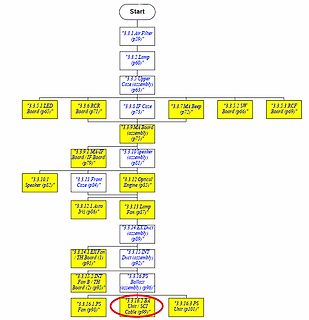
) (p73)
3.3.9.1 MA-IF Board / IF Board (p79)
3.3.10 Speaker (assembly) (p81)
3.3.10.1 Speaker (p82)
3.3.11 Front Case (p84)
3.3.12 Optical Engine (p85)
3.3.12.1 Auto Iris (p86)
3.3.13 Lamp Fan (p87)
3.3.14 EX Duct (assembly) (p88)
3.3.14.1 EX Fan / TH Board (1) (p91)
3.3.15 INT Duct (assembly) (p92)
3.3.15.2 INT Fan B / TH Board (2) (p95)
3.3.16 PS Ballast (assembly) (p96)
3.3.16.1 BA Unit / SCI Cable (p98)
3.3.16.3 PS Unit
operation. Their equation can be written as: 2 2 0.5 V wc = V ’w [(1+ x )/ (1+(k x) )] 5.2.1 where x= 2π a/p 2 0.25 k = √20/π [d c/(300 p)] dcis the coil diameter in metres p is the winding pitch in metres f is in Mhz Notice that the numerator gives the path length of the wire (per meter of coil) and the denominator
Hochfrequenztechnik [Foundations of high-frequency technology], Franz Ollendorff, Springer Verlag 1926. p79-87 Das dynamische Feld der mehrwindigen Spule [Dynamic field of multi-turn coils]. [Ollendorff 1926]. 31 Theory of the Beam-Type TWT. J R Pierce. Proc. IRE. Feb. 1947. p111-123. SeeAppendix B, p121
input/output port 96 I/O A TX2 TX output pin of CAN2 97 P22_0 I/O A General-purpose input/output port INT12 External interrupt input pin P22_2 General-purpose input/output port 98 I/O A INT13 External interrupt input pin
assignment diagram D E 7 6 5 4 3 2 1 0 L A 7 6 5 4 3 2 1 0 7 6 5 4 3 2 1 0 7 6 5 4 0 O D E R 0 R G 1 G B 2 B H H H H H L V V V V VI L V V VI C D R R R L R R R R R G G G G L G G G G B B B B D M O B P E S O D T E S P D T S P D U T T T T T S L D / / / / / D / / / / / D S 3 2 1 D 0 9 8 7 6 5 4/ D 3 S 2 D 1
CURRENT V.S. LEDCTRL o BACKLIGHT CURRENT V.S. LEDCTRL A T60 c it h (160 100 e w R120 L60 T e → I160 B20 a y t B 00 p 0.0.20.0.60.LEDCTRL (b).82.2.22.2.5 0.00.0.40.0LEDCTRL (V)1.82.2.2.42.5 JUN.04, 2009 1 2. MECHAiICAL SPECIFICATIONS r i (D)MODULE SIZE : 165W i s04.44H *9.2D(MAX.) mm (WITHOUT FPC) → g
ANALYZER INSTRUCTION MANUAL 9.3 YTO-CONT/IF Board (5 ) S te p A m p lifie r 20 dB .N R80 10dB 20 dB v- R96 L_# R103 1 L-' P,110 R117 -d' 1 1 R97 R104 R 1 0 5 R ill R112 R 1 1 8 R 1 1 9 R821 1R83 R88 D 1 7 ' R 9 8 018 D19 D20 r013 - J D21 1 dB STEP ATT 0.25 STEP
Michael B. schrieb im Beitrag #7462414: > MPPT wird schon gemacht wo es lohnt. Ja. Aber das bringt nichts wenn das Smartphone die Leistung dann nicht abnimmt. Michael B. schrieb im Beitrag #7462414: >
Zwischenstecker muss ja so eine Art Boostwandler sein. Nehmen wir an der hat 98% Pwirk und der WR hat 96%. dann ist der resultierende Wirkungsgrad 0,98 * 0,96 = 0,94. Also 2% schlechter. Wenn der dann im Mittel 5% mehr aus der PV holt, sind das real nur 3%. Die PV Leistung im Jahresmittel beträgt ja
HIGH VOLTAGE 30 V 110 mA typical typical typical R1 117 K 205 K 309 K R2 13.3 K 13.3 K 13.3 K Cf 220 pF 120 pF 82 pF D1 MBR0520 MBR0530 MBR0540 8.2.2 Detailed Design Procedure 8.2.2.1 Selecting the External Capacitors The best capacitors for use with the LM2733 device are multi-layer ceramic capacitors
2 - E p o e B E T W o v s i T P L 6 l - n 4 l o : n O B i U P p E O I T ) W N r D U o R n E t I W g W A C k D D 2 - a E 4 B 3 E D 4 B ( i a : W b o t B P C M t c P 1 o s r i i c l I M b M b F n N R 6 R 6 C o
15 V 2 5 mA O(min) in IO Output Current V inV O 5 V TJ= 25°C 800 950 1300 mA eN Output Noise (%VO) B =10Hz to 10KHz TJ= 25°C 0.003 % SVR Supply Voltage Rejection I = 40 mA f = 120Hz T = 25°C 60 75 dB O J V inV O 3 V Vripple 1 PP V d Dropout Voltage IO= 100 mA 1 1.1 V IO = 500 mA 1.05 1.15 IO = 800 mA

 Bild
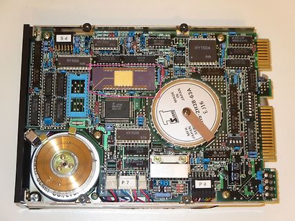
 Bild
 Bild
 Bild