-
Datei
DOGM_SPI.asm
1 4 7 * ; 2 LCD Display RS Keyboard 2 5 8 0 ; 3 Keyboard 3 6 9 # ; 4 ---------I I I I ; 5 -----------+ I I ; 6 LCD SPI clock -------------+ I ; 7 LCD SPI Data ---------------+ LIST P=16F628 ;tell assembler
in „EA DOG-M LCD im SPI-mode“ · Mikrocontroller und Digitale Elektronik ·
-
Datei
new__0.txt
CLEAN SUCCESSFUL (total time: 552ms) make -f nbproject/Makefile-default.mk SUBPROJECTS= .build-conf make[1]: Entering directory 'C:/Users/harms01/Desktop/AN1388_Source_Code_2014_02_14/PIC32_Bootloaders/Firmware/Bootloader/MPLAB_X_Workspace/USB_MSD_Btl_StarterKit.X
in „PIC32MX Bootloader MSB“ · Mikrocontroller und Digitale Elektronik ·
-
PDF
tempmess.pdf
GND +5V GND J3 +5V GND 6 7 Pin 1 = Links (ansicht von vorne) S W B B D D k R R E D D C D 1 3 G G t 2 P P PIC RPo 1 IC1 14 VDD RB7 13 PGD/DB7 +5V 100nF RB6 11 PGC/DB6 GND C4 16 RB5 10 DB5 V OSC1 RB4 9 DB4 5 15 RB3 8 RW + GND OSC2 RB2
-
Datei
retlw.asm
;************************************* ;* Projektname : retlw ;* Datum : 06.05.2009 ;* Prozessor : PIC16F876 ;* Board : easyPIC3 ;* ;************************************** list p=16F876 ; Baustein #include<p16f876.inc> __CONFIG 0x3F72 ; konfigurationsort 16F876 LSB EQU H'0021' MSB EQU H'0022' NUMBER1
in „PIC16F876 Problem mit Tabelle“ · Mikrocontroller und Digitale Elektronik ·
-
Datei
16F876_Prescaler.ASM
**************************************************** ; Files: P16F876A.INC ; ; Hardware: PIC16F876A ; Quarz 4MHz ; Testboard PORTB-LED, PORTC-LED ; ; Notes: ; ;********************************************************************** ;suppressed warnings: errorlevel -207 errorlevel -302 ;MCU-Configuration LIST P=16F876A ; list directive to define processor #INCLUDE <P16F876A.INC> ; processor specific variable definitions __CONFIG _FOSC_XT & _WDT_OFF & _PWRTE_ON & _BOREN_ON & _LVP_OFF & _CP_OFF & _CPD_OFF ;;PIC16F887
in „PIC16F887 Prescaler wird ignoriert“ · Mikrocontroller und Digitale Elektronik ·
-
Datei
Z__hler_Stampede.txt
**************** ; This file is a basic code template for object module code * ; generation on the PIC16F648A. This file contains the * ; basic code building blocks to build upon. * ; * ; Refer to the MPASM User's Guide for additional information on * ; features of the assembler and linker (Document
in „Hilfe für PIC-gesteuerten Zähler“ · Mikrocontroller und Digitale Elektronik ·
-
Datei
PA0_16F57.asm
********************* ; This file is a basic code template for assembly code generation * ; on the PIC16F57. This file contains the basic code * ; building blocks to build upon. * ; * ; Refer to the MPASM User's Guide for additional information on * ; features of the assembler (Document DS33014). * ;
in „PIC16F57 Initialiesierung“ · Mikrocontroller und Digitale Elektronik ·
-
Datei
Si4703.c
WriteI2C( unsigned char data_out ) { SSPBUF = data_out; // write single byte to SSPBUF if ( SSPCON1bits.WCOL ) // test if write collision occurred return ( -1 ); // if WCOL bit is set return negative # else { if( ((SSPCON1&0x0F)!=0x08) && ((SSPCON1&0x0F)!=0x0B) ) //Slave mode only { SSPCON1bits.CKP
in „PIC18F14K50 und I2C“ · Mikrocontroller und Digitale Elektronik ·
-
PDF
RF02_code_en.pdf
output x3..x0: select crystal load capacitor x3 x2 x1 x0 Load capacitor [pF] 0 0 0 0 8.5 0 0 0 1 9.0 0 0 1 0 9.5 0 0 1 1 10.0 …… …… 1 1 1 0 15.5 1 1 1 1 16.0 To integrate the load capacitor internal can not only save cost, but also adjust reference frequency
in „Datenübertragung mit Funkmodul RFM01-RFM02“ · Mikrocontroller und Digitale Elektronik ·
-
 Bild
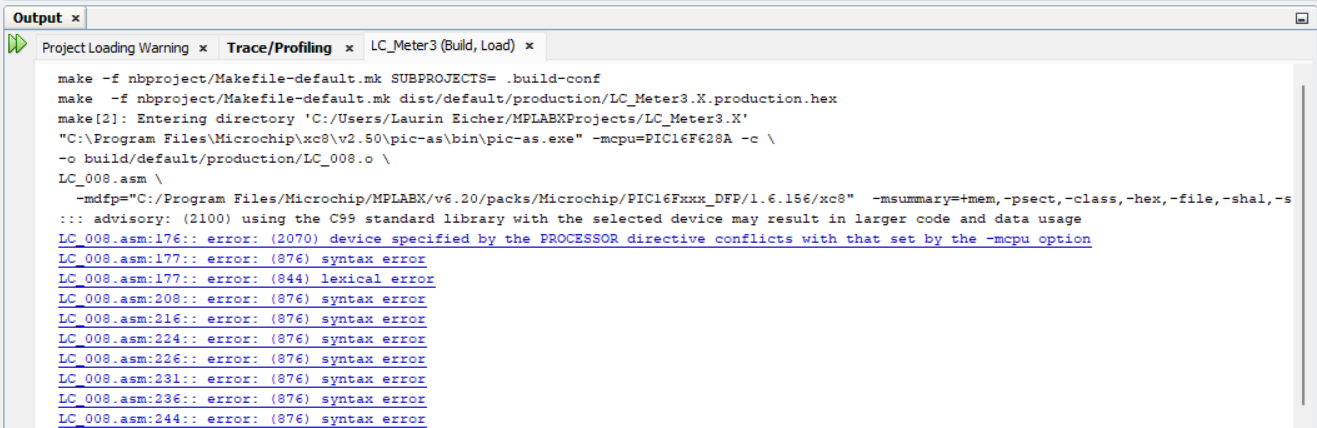
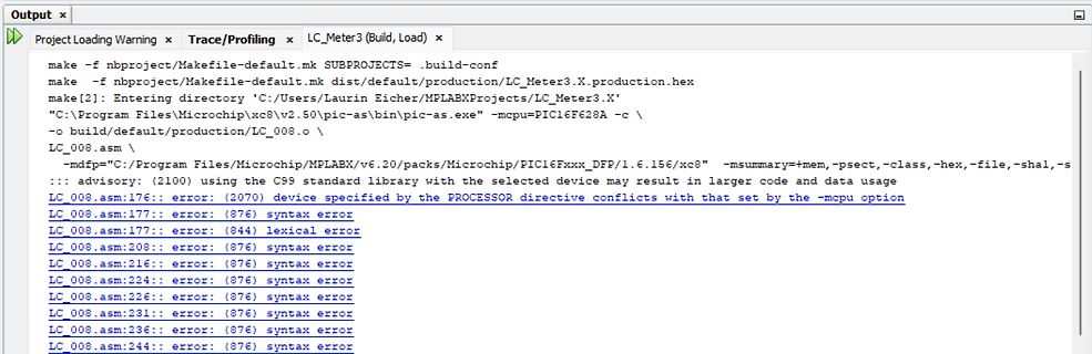
Compiler-Fehlermeldungen in einer Entwicklungsumgebung
make -f nbproject/Makefile-default.mk SUBPROJECTS=.build-conf make -f nbproject/Makefile-default.mk dist/default/production/LC_Meter3.X.production.hex make [2]: Entering directory 'C:\Users\Laurin Eicher\MPLABXProjects\LC_Meter3.X' "C:\Program Files\Microchip\MPLABX\v6.20\pic-as\bin\pic-as.exe" -mcpu=PIC16F628A -c \ -o build/default/production/LC_008.o \ -mdfps="C:\Program Files\Microchip\MPLABX\v6.20\packs\Microchip\PIC16Fxxx_DFP\1.6.156\xc8" -msummary=+mem, -psect, -class
in „Kann assembler file nicht builden“ · Mikrocontroller und Digitale Elektronik · · Screenshots
-
PDF
Platinfuch_IIa_BOM_20210217.pdf
0.015 0.015 14 1 C47 Capacitor 0805 220pF / 50V / NPO Farnell 175-9209 0.017 0.017 15 4 C86, C91, C94, C95 Capacitor 0805 6.8nF / 50V / X7R Farnell 175-9244 0.011 0.046 16 2 C87, C88 Capacitor 0805 22pF / 50V / NPO Farnell
in „Platinfuchs IIa: Isolierter, bidirektionaler 45W DC/DC Wandler zum Laden/Entladen eines Liion-Akkus“ · Projekte & Code ·
-
Datei
18F876_Int_PORTB_Change_01.ASM
********************************************************* ; Files: P16F876A.INC ; HD44780.INC ; ; Hardw.: PIC 16F876A ; Quarzosz. 4MHz ; ;******************************************************************** ; Projekt ; Auslösen des Change-Interrupts an PORTB,RB7:4 mittels
in „PIC16f887 PORTB Interrupt funktioniert nicht“ · Mikrocontroller und Digitale Elektronik ·
-
Datei
PIC_41__2-06_.asm
; Programm LCDEXP0.asm: Demoprogramm für LCD-Modul, angesteuert über Expander PCF8574 ; PIC 16F84, f = 4 MHz, SC = 1us; OUT(sda) an RA0, CLOCK(scl) an RA1, CS an RA2 ; Dieter Kohtz, Juni 2005 ;********************************************************************************************* LIST P = 16F84 ; legt den PIC-Controllertyp fest ; Configuration Bits (aus dem Header File P16F84.inc) _CP_ON EQU H'000F' _CP_OFF EQU H'3FFF' _PWRTE_ON EQU H'3FF7' _PWRTE_OFF EQU H'3FFF' _WDT_ON EQU H'3FFF' _WDT_OFF
in „LCD am I2C initialisieren“ · Mikrocontroller und Digitale Elektronik ·
-
PDF
STM_DEV.pdf
VDDA VSSA GND SS66 SS4 SS55 D STM32F103VE I2 I02 P02 P02 P2 P02 92 D COCK COCK COCK COCK COCK OCK OCK9 I1100n I01n 10P01100nP010n 1P1n 100P01 91 TitleCPU Master Size:A4 Number: 2. Revision1.0 GND Date: 16.01.2010 Time: 17:31:15 Sheet 2
in „STM32 Development Board“ · Mikrocontroller und Digitale Elektronik ·
-
Datei
p18f6622.inc
the following ways: ; ; 1. Command line switch: ; C:\MPASM MYFILE.ASM /PIC18F6622 ; 2. LIST directive in the source file ; LIST P=PIC18F6622 ; 3. Processor Type entry in the MPASM full-screen interface ; 4. Setting the processor
in „PIC18F6620 lesen, schreiben“ · Mikrocontroller und Digitale Elektronik ·
-
Datei
blinker.asm
**************** ; This file is a basic code template for object module code * ; generation on the PIC16F876. This file contains the * ; basic code building blocks to build upon. * ; * ; Refer to the MPASM User's Guide for additional information on * ; features of the assembler and linker (Document DS33014F
in „pic oszillator schwingt nicht“ · Mikrocontroller und Digitale Elektronik ·
-
PDF
Frequenzzaehler_Sprut211120A.pdf
4 MCLR RB0 6 E S / 4 5 6 7 P Poti R20 33p 5p +5V R R E D D D D 2k2 +5V GND C14 T0CKI/RA4 3 GND " C16 D RA3 2 m G Q6 D C3 C15 100n RA2 1 +5V A GND SBF256 C1 N 33 18 LSP7 Taster g 100p 10n G10n R19 GND GND GND GND 5 RA1 17 R17 n X2 VSS RA0 10k Eingangswahl g C4 100k R3 GND 33k PIC16F628 LSP8 e H 33 IC2
in „Frequenzzähler Sprut 1GHz“ · Mikrocontroller und Digitale Elektronik ·
-
Datei
irmp-libopencm3.diff
-------------------------------------- */ diff --git a/irmpsystem.h b/irmpsystem.h index 25bacb2..e1fbc97 100644 --- a/irmpsystem.h +++ b/irmpsystem.h @@ -26,6 +26,9 @@ # define PIC_C18 #elif defined(__PCM__) || defined(__PCB__) || defined(__PCH__) // CCS PIC compiler # define PIC_CCS +#elif defined(STM32F1) // ARM STM32 with libopencm3 +# define ARM_OPENCM3 +# define F_CPU (SysCtlClockGet()) #elif defined(STM32L1XX_MD) || defined(STM32L1XX_MDP) || defined(STM32L1XX_HD) // ARM STM32 # include <stm32l1xx.h
in „IRMP - Infrared Multi Protocol Decoder“ · Projekte & Code ·
-
Datei
display_projekt.asm
Source file: display_projekt.asm ; Von: Marvin Wenzel ; Date: 09.01.2014 ; Software: MPASM ; Hardware: PIC16F8xx Programmer Module ; Controller PIC16F887 ; ; RD0...RD7: Datenbus ; RB0: C/D Data input (L)/command input(H) ; RB1: Data write (L) ; RB2: Data read (L) ; RB3: Chip enable (L) ; RB4: Reset Display
in „T6963C: kann keine Daten schreiben“ · Mikrocontroller und Digitale Elektronik ·
-
PDF
DE-DP004_Ver1.0_EN.pdf
cable is so long, here 74HC00 is used as NOT gate, and 2 gates in series is a buffer. DE-DP004-Ver1.0-page 10 © 2004-2008 Sure ElectronicsInc. 4 inch Character Height 7-segment LED Information Board User’s Guide Chapter3.Sample Codes 3-1. LED Segment Drive Demo Board’s Schematic +5V R1 U1 PIC10F200
in „! Vorsicht NEWB 7-Segmentanzeigen via PC ansteuern“ · Mikrocontroller und Digitale Elektronik ·
-
Datei
CodeBlocksSDCC_Wie.txt
dem "Compiler Settings" und unter dem Reiter "Compiler-Flag", stellen Sie entweder die CPU-Flag für PIC 16 oder 14 Bit-Befehle. In der Menü Project->Build options->Compiler Settings->Compiler Flags: stellen Sie entweder die CPU-Flag für PIC 16 oder 14 Bit-Befehle. In der Menü Project->Build options->Compiler Settings->Other options: -p18f2680 --obanksel=2 --optimize-cmp --optimize-df --use-non-free In der Menü Project->Build options->Linker settings->Links libraries: C:\Program Files\ sdcc\lib\pic16\libc18f.lib
in „Compilieren in CodeBlocks geht nicht“ · Mikrocontroller und Digitale Elektronik ·
-
PDF
t69b1.pdf
C5-C9 1uf smd cap IC4 Max637 R1,R3,R4 4.7k smd res LM7805 regulator R2 330 smd res X1 20Mhz resonator R5 10k or 20k POT Printed circuit board D1 IN4001 diode DB9F connector D2 IN4148 diode 2x10 Female LCD header
in „LCD240128A an PIC 18F4550“ · Mikrocontroller und Digitale Elektronik ·
-
PDF
XT-LP_fuer_3_DOM_Plan.pdf
3 1 3 5 7 9 1 3 5 A1D P6 A8 A8 J 1 1 1 N 17 P7 R3 A7 5 A7 D0 13 D0 S3 G 220R A6 6 A6 D1 14 D1 1 1 N16 Q0.3 3 Q0 A5 7 A5 D2 15 D2 2 2 O15 Q1.3 5 Q1 IC4E IC4F A4 8 A4 D3 17 D3 3 3 14 Q2.3 7 11 10 13 12 A3
in „Decodier-Logik neu anpassen“ · Mikrocontroller und Digitale Elektronik ·
-
Datei
test.lst
Microchip Technology PIC LITE Macro Assembler V1.21 build 54009 Sat Dec 07 16:00:07 2013 Microchip Technology Omniscient Code Generator (Lite mode) build 54009 1 processor 16F876 2 opt pw 120 3 opt lm 4 psect maintext,global
in „[C] XC8 verschwendet Speicher“ · Mikrocontroller und Digitale Elektronik ·
-
Datei
ffconf.h
is 1, this option selects the character encoding on the file to / be read/written via string I/O functions, f_gets(), f_putc(), f_puts and f_printf(). / / 0: ANSI/OEM / 1: UTF-16LE / 2: UTF-16BE / 3: UTF-
in „Problem mit VS1053“ · Mikrocontroller und Digitale Elektronik ·
-
Datei
main.asm
********************* ; This file is a basic code template for assembly code generation * ; on the PIC16F887. This file contains the basic code * ; building blocks to build upon. * ; * ; Refer to the MPASM User's Guide for additional information on * ; features of the assembler (Document DS33014). *
in „PIC16F887 SPI“ · Mikrocontroller und Digitale Elektronik ·
-
PDF
Platinfuchs_IIa_Schematic-and-Layout.pdf
VZK* *3V3* *3V3* T2 T3 VZK VZK BC846C BC846C 9 8 7 6 5 n 8 7 6 5 Z Z T C24 i C25 C10 V C11 V - 2,2µF a - 2,2µF 22µF 22µF B C26 R14 R15 1 C A C t 16V a 1 C A C t 16V 16V 16V B 100nF 130K *VCC* 47K 5 N u V u p 5 N u V u U17A M O O e M O O 7,86V TS393 L l L 3 i 1 *GND* t GND GND GND *GND* 2 C A E B e C
in „Platinfuchs IIa: Isolierter, bidirektionaler 45W DC/DC Wandler zum Laden/Entladen eines Liion-Akkus“ · Projekte & Code ·
-
Datei
timer_opt.asm
*********************************************************** ; **** **** ; **** Kurzzeit- Timer mit PIC16F876(A) **** ; **** Anschluß 1 LCD-Displays HD44780 8x2 **** ; **** Zeile 1: Zeitanzeige MM:SS,HH **** ; **** Zeile 2: Anzeige von Stausmeldungen **** ; **** Bedienung über 4 Taster **** ; **** BT_Set
-
PDF
DE200610__1_.pdf
RB0 RD3 22 34 21 C3 1µ 35 RB1 PIC16F877 RD2 20 RB2 RD1 R5 C13 25V 36 RB3/PGM RD0 19 2 37 1 K1 1µ RB4 100n 1 C1+ V+ 16 38 RB5 RE0/RD/AN5 8 1 25V 39 9 L1 R18 RB6/PGC RE1/WR/AN6 Ω 6 C1 3 C1– IC4 40 RB7/PGD RE2/CS/AN7 10 330µH
in „ekg schaltung aus heft 10/2006“ · Analoge Elektronik und Schaltungstechnik ·
-
Datei
7Segment_0-9999.asm
; Microcontroller model: PIC16F84 ; Lauflicht am Port B ; Taktquelle: 4MHz ; ; loops Equ 0x22 loops2 Equ 0x23 Backup Equ 0x24 Init bsf STATUS, RP0 movlw B'00000000' movwf TRISB movwf TRISA bcf STATUS, RP0 clrf PORTB clrf PORTA
in „Multiplex PIC16F84A Zähler“ · Mikrocontroller und Digitale Elektronik ·
-
Datei
LCD_2x16_Hallo_Welt_V_3.asm
;********************************************************************** ; * ; Filename: LCD_2x16_test * ; Date: 01.02.2014 * ; File Version: 1.0 * ; * ; Author: ICU * ; Company: * ; * ; * ;********************************************************************** ; * ; Files Required: P16F877.INC *
in „erledigt -> LCD Ansteuerung mit Pic u. Assembler - Problem“ · Mikrocontroller und Digitale Elektronik ·
-
PDF
MCP1703_MIC.pdf
. DS22049D-page 7 MCP1703 Note: Unless otherwise indicated: V = 1.8V,RC OUT = 1 µF Ceramic (X7R), C IN = 1 µF Ceramic (X7R), I = 100LµA, T = +25°C, V = V + V or 2.7V, whichever is greater. A IN OUT(MAX) DROPOUT(MAX) 1.20 0.20 V = 2.5V VOUT= 2.5V OUT ) 1.00 V = 16V
in „Was ist das für ein IC“ · Mikrocontroller und Digitale Elektronik ·
-
Datei
TECHLIB_APR07_Dir.txt
16:38 2.330.349 t24_44_84_F0207.pdf 12.03.2007 16:38 296.786 t24_44_84_F0207s.pdf 12.03.2007 16:38 2.498.284 t25_45_85_J1206.pdf 12.03.2007 16:38 253.733 t25_45_85_J1206s.pdf 12.03.2007 16:38 1.484.845
in „STK500 CD ISO Image“ · Mikrocontroller und Digitale Elektronik ·
-
PDF
93C86.pdf
obtained from Microchip’s web site at www.microchip.com. 1996-2012 Microchip Technology Inc. DS21132F-page 3 93C76/86 TABLE 1-3: INSTRUCTION SET FOR 93C76: ORG=1 (X16 ORGANIZATION) Instruction SB Opcode Address Data In Data Out Req. CLK Cycles READ 1 10 X A8 A7 A6 A5 A4 A3 A2 A1 A0 — D15 - D0 29 EWEN
in „asm Code für EEPROM 93C86“ · Mikrocontroller und Digitale Elektronik ·
-
Datei
AnaltogDigitalConverter.asm
;***************************************************************************** list p=16f877 ;Typ-Wahl PIC16F877 #include <p16f877.INC> ;Bezeichnungen von PIC16F877 verwenden ;Errorlevel -302 ;***************************************************************************** ;Konfiguration festlegen
in „Analog Digital Converter kleines Problem (PIC)“ · Mikrocontroller und Digitale Elektronik ·
-
Datei
RSKurzeAuswertung.asm
------------------------------------------- ;-----------------------------------Belegung des PICs (PIC 16F877)------------------------- ; ; ________________ ; MCLR 5V--------1| |-------Rel 16 RB7 ; RA0 Kanalsw1------2| |-------Rel 15 RB6 ; RA1 Kanalsw2------3| |-------Rel 14 RB5 ; RA2 Kanalsw3------4
in „PIC nach ändern von Code undefiniertes herumwüten des uC“ · Mikrocontroller und Digitale Elektronik ·
-
PDF
Real_Time_Clock.pdf
should ensure that your layout uses good PCB layout techniques so noise does not couple onto the Timer1/Timer3 oscillator lines. DS39514A-page 14-16 2000 Microchip Technology Inc. PIC18F2455/2550/4455/4550 12.3.3 TIMER1 OSCILLATOR LAYOUT 12.5 Resetting Timer1 Using the CCP CONSIDERATIONS Special Event
in „Uhr mit PIC18“ · Mikrocontroller und Digitale Elektronik ·
-
PDF
EMS_PIC.pdf
_RX GND 4 V- 3V3OUT CBUS2 14 V R10 13 RC1/T1OSI RC6/TX/CK 16 232_TX 7 C2+ GND 15 CBUS3 12 GND +5 R9 14 RC2/CCP1 RC5/SDO 15 R11 V 1 C 5 USBD+ 16 USBDP CBUS4 + 10k RC3/SCK/SCL RC4/SDI/SDA + C2- USBD- USBDM 26 10k PIC18F2580-I/SP 10k 11 14 25 TEST Mode 232_TX 10 T1IN T1OUT 7 GND 7 1 O SOFT_TX 12 T2IN T2OUT 13 GND GND 18 2 2 5 232_RX 9 R2OUT R2IN 8 GND 21 3 3 4 SOFT_RX MAX232 FT232RL GND SW2 GND 08.09.2011 20:40:05 f=0.90 C:\Eigene Daten\Projekte\Eagle\EMS_PIC\EMS_PIC.sch
in „Buderus EMS-"Gateway" mit PIC18F / Sammelbestellung“ · Haus & Smart Home ·
-
PDF
EMS_PIC.pdf
_RX GND 4 V- 3V3OUT CBUS2 14 V R10 13 RC1/T1OSI RC6/TX/CK 16 232_TX 7 C2+ GND 15 CBUS3 12 GND +5 R9 14 RC2/CCP1 RC5/SDO 15 R11 V 1 C 5 USBD+ 16 USBDP CBUS4 + 10k RC3/SCK/SCL RC4/SDI/SDA + C2- USBD- USBDM 26 10k PIC18F2580-I/SP 10k 11 14 25 TEST Mode 232_TX 10 T1IN T1OUT 7 GND 7 1 O SOFT_TX 12 T2IN T2OUT 13 GND GND 18 2 2 5 232_RX 9 R2OUT R2IN 8 GND 21 3 3 4 SOFT_RX MAX232 FT232RL GND SW2 GND 08.09.2011 20:40:05 f=0.90 C:\Eigene Daten\Projekte\Eagle\EMS_PIC\EMS_PIC.sch
in „Junkers HT-Bus Heatronic 3 Schnittstelle“ · Haus & Smart Home ·
-
Datei
hallo.ASM
********************* ; This file is a basic code template for assembly code generation * ; on the PIC16F876. This file contains the basic code * ; building blocks to build upon. * ; * ; Refer to the MPASM User's Guide for additional information on * ; features of the assembler (Document DS33014). *
in „pic PortB-Ausgang“ · Mikrocontroller und Digitale Elektronik ·
-
PDF
8-bit-MCU-Overview.pdf
D u S S C P C e T oT i C x M v u l l i P P S E S S I A A C A D O T I R Z ( 8 1 Q W W ( W R 8 1 1 C M C C P B W F U U 2I S I S Q Q w L E D E M S S p ATtiny102/104 8/14 1 0.032 1.8–5.5 12 10 5/8 2 2 1 4 ATtiny20x/40x/80x/160x 8–24 2–16 Up to 1 1.8–5.5 20 10 12
in „Moderne AVR (Nachfolger Atmega und Attiny)“ · Mikrocontroller und Digitale Elektronik ·
-
PDF
8-bit-MCU-Overview.pdf
D u S S C P C e T oT i C x M v u l l i P P S E S S I A A C A D O T I R Z ( 8 1 Q W W ( W R 8 1 1 C M C C P B W F U U 2I S I S Q Q w L E D E M S S p ATtiny102/104 8/14 1 0.032 1.8–5.5 12 10 5/8 2 2 1 4 ATtiny20x/40x/80x/160x 8–24 2–16 Up to 1 1.8–5.5 20 10 12
in „AVR®DD family, low pin count devices“ · Mikrocontroller und Digitale Elektronik ·
-
Datei
DKW.c
/*-------- Programm 'DKW.c' -- 12.01.2011. MASTER (PIC 16F877) hat einen MSSP-Modul (I2C) /*die diesem Programm zugrunde liegenden Anweisungen stammen aus dem HI-TECH-Compiler (PICCLITE) (i2c.c, usw.) Funktionsweise dieses Modules, siehe 'DKW-Text.text'
in „HO-Eisenbahn-Weichenmodul“ · Mikrocontroller und Digitale Elektronik ·
-
PDF
23x256.pdf
Inputs tiedCCo V or VSS D010 C INT Input capacitance 7 pF VCC = 0V, f = 1 MHz, Ta = 25°C (Note 1) D011 VDR RAM data retention — 1.2 — V voltage(2) Note 1: This parameter is periodically sampled and not 100% tested. Typical measurements taken at room temperature
in „AVR: Port wiederholt schnellstmöglich auslesen?“ · Mikrocontroller und Digitale Elektronik ·
-
PDF
CAN_uC_V2_01Jan2013_Stromlauf.pdf
2 GNDP RB1_INT1 C12 100n 7 VDD RE2 27 1 8 AN7 CAN_H RB0 PIC18F4685(TQFP44) RE1 AN6 4 5 8 26 2 7 RN5 CAN_L 1 RN6 1 8 9 RB1 RE0 25 3 6 100R AN5 1 2 R11 L1 2 7 10RB2 R RA5 24 4 5 AN4 D1 Extern N.B. VCC 100R RB3 C C B B B B7 C A A A A RA4 C14 N.B. 2 B82790-51uH 3 6 11 N N R R R R M R R R R 23 1 2 <-- C statt R für VCAP statt RA4 Extern PESD1CAN C15 4n7 R13 4 1 8 STBN TXD 1 12 13 14 15 16 119 20 21 22 bei PIC18F46k80 Analog Oder: 2 1 1 2 7CANH GND 2 1 2 GNDP 18 VDD R12 100R PESD2CAN, 1 0R CANL
in „Anforderungssammlung CAN Hausbus mit PIC µC“ · Haus & Smart Home ·
-
PDF
Designing_a_digital_compass.pdf
www.microchip.com © 2005 Microchip Technology Inc. DS00996A-page 13 AN996 APPENDIX B: SCHEMATICS FIGURE B-1: SHEET 1 OF 3 F μ μ . 1 F 0 R V F 4 μ 1 . S 0 4 0 6 D S C V V 0 M 3 F 8 μ 2 2 I . S F _ 1 2 0 E 2 P F V 1 R I C S P M V F F μ μ . . 3 3 0 2 E C S 1 V V V I T V E V E V F μ . 3 DS00996A-page 14 © 2005
in „Kompassmodul HDMM01 von Pollin“ · Mikrocontroller und Digitale Elektronik ·
-
PDF
040398_asm.pdf
040398.asm Page 1 ;File: DISEQC05.ASM Version 05/06 ;author: W. Waetzig 03.0 6.2006 ;processor: PIC 16F628 ;assembler: MPASM.EXE by MicrochiP ;modules used: ; with driver for LCD−display with 2*16 bytes ; with interface
in „DiseqC (22kHz) messen“ · Mikrocontroller und Digitale Elektronik ·