-
PDF
A4979-Datasheet.pdf
1, VBB > 5.6 V – 100 200 mV Motor Bridge Output V = 50 V, I = –1.5 A, T = 25°C – 500 650 mΩ High-Side On-Resistance R BB OUT J ONH V BB= 7 V,OUT = –1.5 A,JT = 25°C – 625 800 mΩ High-Side Body Diode Forward Voltage V FH – – 1.4 V V BB= 50 V,OUT = 1.5 A,JT = 25°C – 500 650 mΩ Low-Side On-Resistance RONL
in „Schrittmotor-Treiber-IC mit umfangreichen Programmiermöglichkeiten und Diagnose-Funktionen“ · Mikrocontroller und Digitale Elektronik ·
-
Datei
partdb-autoprice.py
www.reichelt.de" header["Cookie"] = "USERDOMAIN=www.reichelt.de; last_viewed_articles[0]=23445; " +\ "Reichelt_SID=" + sessionId + "; Reichelt_PROVID=NewSID" header["Content-Type"] = "application/x-www-form-urlencoded" header["Content-Length"] = str(len(body)) http.request("POST", "/index.html?SID=" + sessionId
in „PART-DB RW 1.2“ · Projekte & Code ·
-
PDF
Leistung2_neu_V7brd_breite_neu.pdf
D B D B D B D B 2 TLP250F 1 7 GND_T1 GND_T1 GND_T1 GND_T2 GND_T2 X8-2 C 4 MSTBV2 + OP_1_HIGH_SIDE_LEFT1 +15V_T1 8 +15V_T2 2 7 R2 X9-1 1 T1.2 3 6 5R +C14 C6 GND_T1 5 47µ 100n GND_T2 2 TLP250F 2 7 GND_T2 X9-2 C 4 MSTBV2 + P$1*4T1 OP_2_HIGH_SIDE_RIGHT ST6,3W +15V_T2 U1 8 +15V +VC + 2 7 R8 X7-4 4 CURRENT
in „Positiven und negativen Strom messen“ · Analoge Elektronik und Schaltungstechnik ·
-
Datei
kev.py
') self.geometry('300x50') self.label = T.Label(self, text='Hallo Unterfenster.') self.label.pack(side=T.TOP) self.button = T.Button(self, text="Exit", command=self.destroy) self.button.pack(side=T.TOP) class MainWin(T.Tk): def __init__(self, *args, **kwargs): T.Tk.__init__(self, *args, **kwargs) self.button = T.Button(self, text="Exit", command=self.destroy) self.button.pack(side=T.TOP) self.button = T.Button(self, text="Subbie", command=self.subbie) self.button.pack(side=T.TOP) self.frame = T.Frame(self, relief='ridge', borderwidth=5) self.frame.pack(side=T.TOP, fill='both'
-
PDF
Z5730M__Nixie_.pdf
M Z 5900 M Z 8700 M Display Symbols 0 to 9 0 to 9 0 to 9 bi-quinary Decimal point right left both sides Viewing direction side side side side Character height (mm) 13 13 10 15.5 Maximum viewing distance (m) ~8 ~8 ~5 ~10 Typical values Ignition voltage Vign 150 150 150 150 Maintaining voltage Vmaint 140
-
PDF
Infineon-AN-1035-ApplicationNotes-v29_01-EN.pdf
copper tin-silver-copper alloy (Sn96.5 Ag3.0 Cu0.5) to improve can, which is bonded to the drain side of the silicon die. The can has two contact areas, both of which performance with lead-free pastes and identified bya PbF must be soldered to the substrate although one can be suffix after the part
in „Datenblatt zu DirectFet Mosfet gesucht“ · Analoge Elektronik und Schaltungstechnik ·
-
PDF
ETXDesignGuide120.pdf
SIDE_D3 72 PIDE_D12 23 SMBCLK 24 SMBDATA 73 SIDE_D11 74 PIDE_D3 25 SIDE_CS3# 26 SMBALRT# 75 SIDE_D4 76 PIDE_D11 27 SIDE_CS1# 28 DASP_S 77 SIDE_D10 78 PIDE_D4 29 SIDE_A2 30 PIDE_CS3# 79 SIDE_D5 80 PIDE_D10 31 SIDE_A0 32 PIDE_CS1# 81 VCC 82 VCC 33 GND 34 GND 83 SIDE_D9 84 PIDE_D5 35 PDIAG_S 36 PIDE_A2 85 SIDE_D6 86 PIDE_D9 37 SIDE_A1 38 PIDE_A0 87 SIDE_D8 88 PIDE_D6 39 SIDE_INTRQ 40 PIDE_A1 89 GPE2# 90 CBLID_P
in „Entwicklung eines ETX Basisbords“ · Mikrocontroller und Digitale Elektronik ·
-
 Bild
Bild
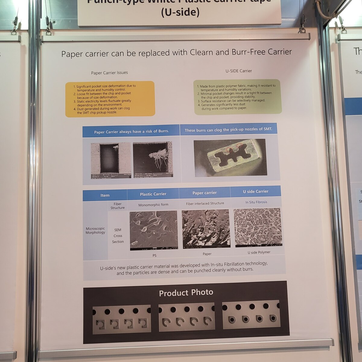
Infoplakat zu Kunststoff-Carrier-Tape für SMT-Bauteile
Punch-type White Plastic carrier tape (U-side) Paper carrier can be replaced with Clearn and Burr-Free Carrier Paper Carrier Issues 1. Significant pocket size deformation due to temperature and humidity control 2. Loose fit between the chip and
in „Electronica 2024, Tag 4 und wrap-up“ · Mikrocontroller und Digitale Elektronik · · Fotos
-
PDF
Schuetz.pdf
Bild4zeigtdietypischeTopologieeinerSchaltungzum Ansteuern eines Hochspannungs-Schützes. Es handelt sich umeine diskrete, aus High-Side- und Low-Side-Trei- bernaufBasisderVIPower-TechnikbestehendeSchaltung, die neben der Ansteuerung auch Schutz- und Diagnose- i r funktionenübernimmt. e WährendderHigh-Side-TreiberdasStromprofilzurkor
in „Gelesen und interessant gefunden: Relais per Brücke ansteuern“ · Analoge Elektronik und Schaltungstechnik ·
-
PDF
Cascaded_PP_Buck.pdf
PUSTAGELL buck regulator cascaded by a push-pull transformer-isola- N : N : 1 : 1 tion stage. On the left side of V VSW L1 VPP L2 V IN OUT thefigurearethebuckswitch, C1 C2 freewheeling diode, and in- ductor. On the right side are the output capacitor and push-pull isolation trans- former.If thepush-pullisola
in „Cascaded Buck - Push Pull Wandler“ · Mikrocontroller und Digitale Elektronik ·
-
PDF
AN296067-Latching-Switch-Hall-Effect-IC-Basics.pdf
; www.allegromicro.com can see, because of the very low saturation voltage the power to the front side (the package branded face) than to the back side. dissipated in the output is not a huge concern. For example, for the “UA” package, the chip with the Hall ele- ment is 0.50 mm inside the branded face
in „Hallsensoren Unterschiede?“ · Mikrocontroller und Digitale Elektronik ·
-
 Bild
Bild
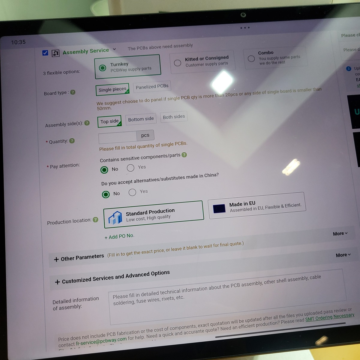
Abfotografierter Bildschirm einer PCB-Assembly-Webseite
Single pieces Panelized PCBs We suggest choose to panel if single PCB qty is more than 20pcs or any side of single board is smaller than 50mm. Assembly side(s): Top side Bottom side Both sides Quantity: pcs Please fill in total quantity of single PCBs. Contains sensitive components/parts: No Yes Do you
in „EmbeddedWorld 2025, Tag 2 – Messtechnik und mehr“ · Mikrocontroller und Digitale Elektronik · · Fotos
-
PDF
C_CABLINE_E.pdf
20142-*50U-*** 29.5 30.3 26.2 24.5 33.9 B C 2.04 D 0.6 0.5 1.02 . 2 . P/N 20142-***U-*** . 7 (PLUG SIDE) 5 . 1 2.24 E P/N 20198-0**E-*** 3 (RECEP. SIDE) 8 ( P C B . RECEPTACLE MATED VIEW POS. PART NO. A B C D E F G 20p 20198-020E-*** 18.9 10.6 9.5 13.2 15.7 10.4 17.0 30p 20198-040E-*** 28.9 20.6 19.5
in „Apple Imac- IPEX LCD Verbindung beim Display abgerissen- HILFE“ · PC Hard- und Software ·
-
Datei
Buttontest2.py
Hauptfenster.title ("Buttontest1") # Rahmen1 Rahmen1 = Frame(Hauptfenster, background = "#002040") Rahmen1.pack(side = TOP, fill = X) # Rahmen2 Rahmen2 = Frame(Hauptfenster, background = "#002040") Rahmen2.pack(side = TOP, fill = X) # Rahmen3 Rahmen3 = Frame(Hauptfenster, background = "#002040") Rahmen3.pack(side
-
PDF
MT79338.pdf
Performance Single Stage, High PFC, AC-DC LED Driver DESCRIPTION FEATURES MT79338 is a single-stage,primary side control Single-stage Active PFC for high power AC-DC LED driver with active power factor factor and low THD correction. MT79338 integrates on-chip PFC Primary side control eliminates opto-coupler
-
PDF
ISO124P_datasheet.pdf
–VS2 Gnd 2 8 9 +VS2 Gnd 2 14 15 +VS2 Pin Functions PIN I/O DESCRIPTION NAME SOIC SOIC 8 14 – Low-side ground reference GND 16 28 – High-side ground reference VIN 15 27 I High-side analog input VOUT 7 13 O Low-side analog output +VS1 1 1 – High-side positive analog supply –V 2 2 – High-side negative
in „Schaltungsaufbau Isolierverstärker für Analogsignal mit Texas Instr. ISO124“ · Analoge Elektronik und Schaltungstechnik ·
-
PDF
LTC4151.pdf
0.125 0.40 ± 0.10 TYP 6 10 0.70 ±0.05 3.55 ±0.05 1.65 ±0.05 3.00 ±0.10 1.65 ± 0.10 2.15 ±0.05 (2 SIDES) (4 SIDES) (2 SIDES) PIN 1 NOTCH PIN 1 R = 0.20 OR PACKAGE TOP MARK 0.35 × 45° OUTLINE (SEE NOTE 6) CHAMFER (DD) DFN REV C 0310 5 1 0.25 ± 0.05 0.200 REF 0.75 ±0.05 0.25 ± 0.05 0.50 0.50 BSC BSC 2.38 ±0.10 2.38 ±0.05 (2 SIDES) (2 SIDES) 0.00 – 0.05 BOTTOM VIEW—EXPOSED PAD RECOMMENDED SOLDER PAD PITCH AND DIMENSIONS NOTE: 1. DRAWING TO BE MADE A JEDEC PACKAGE OUTLINE M0-229 VARIATION OF (WEED-2). 4. DIMENSIONS OF EXPOSED
in „DC Wattmeter Leistungsmesser selber bauen - Eigenbau - low cost Assembler ATmega SA56“ · Projekte & Code ·
-
PDF
lm5165.pdf
TYPE (1) DESCRIPTION NO. NAME Switching node that is internally connected to the drain of the high-side PMOS buck switch and the 1 SW P drain of the low-side NMOS synchronous rectifier. Connect to the switching side of the power inductor. Regulator supply input pin to high-side power MOSFET and internal
in „Stromverbrauch Schaltregler“ · Analoge Elektronik und Schaltungstechnik ·
-
PDF
Service_manual_casio_px-720_px-720c_piano.pdf
PCB – 12 – ■ To remove the CN-PANEL 2. Remove 4 screws and the CN-PANEL. CN-PANEL ■ Removing the Side block 1. Remove the 6 screws.(left and right). <The left side> <The right side> 2. Remove the side units (left and right). – 13 – ■ Disassembling the left side unit (M681-CNA1 PCB, M681-CNA2PCB) 1.
in „E-Piano Casio PX-720C rauscht und kratzt“ · Analoge Elektronik und Schaltungstechnik ·
-
Datei
partdb-autoprice.py
www.reichelt.de" header["Cookie"] = "USERDOMAIN=www.reichelt.de; last_viewed_articles[0]=23445; " +\ "Reichelt_SID=" + sessionId + "; Reichelt_PROVID=NewSID" header["Content-Type"] = "application/x-www-form-urlencoded" header["Content-Length"] = str(len(body)) http.request("POST", "/index.html?SID=" + sessionId
in „PART-DB RW 1.2“ · Projekte & Code ·
-
Datei
cub_2_rubik_pattern.py
manpages.ubuntu.com/manpages/xenial/man1/rubiks_dikcube.1.html # Output examples: # F1: turn front side CW (as seen from top of this side) # F2: turn front side 180° # F3: turn front side CCW # B1: turn back side CW (as seen from top of the back side) # CW: clock wise # CCW: counter clock wise #######
-
PDF
M12021PB_SM_PANASONIC_EN.pdf
SCREWS & WASHERS XTV3+15BFN Scew (P.. BoardH oler) XTV3+15BFN Screw (PC Board Holder) XTV3+8BFN Screw (Side Plate XTB4+25BFN Screw (Side Plate-Front) XWA3B Washer (Side Plate) XTV3+8BFN Screw (Side Plate) XTB4+20BFN Screw (CRT) XWA4B Washer (CRT) XTB4+8BFN Screw (Side Plate Bracket) XTB4+20BFN Screw (CRT) XWG5H14 Washer (CRT) XWA3B Washer (Side Plate-Back) XWA4B Washer (CRT Side Plate-Front) XWG5H14 Washer (CRT) Model No. M-12021PB/M-12021NB TUW81962-1 Side Plate (Right) TUW81963-1 Side Plate (Left) Model No. M-K12004NB/M-K12001NB TUX80849
in „CRT Monitor gegen VGA Monitor tauschen“ · Analoge Elektronik und Schaltungstechnik ·
-
PDF
M12021PB_SM_PANASONIC_EN.pdf
SCREWS & WASHERS XTV3+15BFN Scew (P.. BoardH oler) XTV3+15BFN Screw (PC Board Holder) XTV3+8BFN Screw (Side Plate XTB4+25BFN Screw (Side Plate-Front) XWA3B Washer (Side Plate) XTV3+8BFN Screw (Side Plate) XTB4+20BFN Screw (CRT) XWA4B Washer (CRT) XTB4+8BFN Screw (Side Plate Bracket) XTB4+20BFN Screw (CRT) XWG5H14 Washer (CRT) XWA3B Washer (Side Plate-Back) XWA4B Washer (CRT Side Plate-Front) XWG5H14 Washer (CRT) Model No. M-12021PB/M-12021NB TUW81962-1 Side Plate (Right) TUW81963-1 Side Plate (Left) Model No. M-K12004NB/M-K12001NB TUX80849
in „Heidenhain Monitor BE 212 für TNC 351“ · Analoge Elektronik und Schaltungstechnik ·
-
PDF
90000897.pdf
on TTL, mark, -V on line side On Logic 0 on TTL, space, +V on line side CR8 DSR, Primary SerialPort Green CR9 CTS, Primary SerialPort Yellow On Logic 1 on TTL, mark, -V on line side CR10 CTS, Primary SerialPort Green On Logic 0
in „[V] WEITERE gebrauchte DIGI-Connect-ME LAN-Seriell Module (10€/St.)“ · Markt ·
-
PDF
TEA1716T.pdf
November 2012 8 of 47 NXP Semiconductors TEA1716T Resonant power supply control IC with PFC 7.2.3 High-side driver floating supply (SUPHS pin) The high-side driver is supplied by an external bootstrap buffer capacitor, CSUPHS . The bootstrap capacitor is connected between the high-side reference, the HB pin
in „Reparatur Schaltnetzteil“ · Analoge Elektronik und Schaltungstechnik ·
-
PDF
ZXGD3105EV1_User_Guide_Issue_1..pdf
the board driving a MOSFET for high side rectification. Low side synchronous rectification 1. Remove the original Schottky from the power supply. 2. Apply a short across the Schottky’s K and A terminals. 3. Cut the track connecting the negative
in „SPICE Model einbindung problem“ · Analoge Elektronik und Schaltungstechnik ·
-
PDF
AP8012.pdf
DESCRIPTION Top View Top View Pin # Symbol Function 1,2 GND Sense FET source terminal on primary side and internal control ground. 3 COMP Feedback input defines the peak drain MOSFET current. Positive supply voltage input. Although connected to an auxiliary transformer winding, current is supplied from
in „Startelko AP8012 5V 1A Netzteil“ · Analoge Elektronik und Schaltungstechnik ·
-
PDF
AP8012.pdf
DESCRIPTION Top View Top View Pin # Symbol Function 1,2 GND Sense FET source terminal on primary side and internal control ground. 3 COMP Feedback input defines the peak drain MOSFET current. Positive supply voltage input. Although connected to an auxiliary transformer winding, current is supplied from
in „Netzteilmodul HLK-PM01“ · Mikrocontroller und Digitale Elektronik ·
-
Datei
bauteile.txt
37V R: 0,23 (TO220) 23x BUZ102S Inf N-Kanal Power FET C: 2,36 (TO220) 0,50 5x BTS432 Inf Power High-Side-Switch R: 3,25 (TO220) 0,75 1x BUK213 High-Side-Switch DPAK 13x 78M15 ST Spannungsregler 15V 4x 78M05 ST Spannungsregler 5V SO8 10x 78L05A TI Spannungsregler 5V R: 0,12 4x LM317 Nat. Spannungsregler
in „(V) Diverse SMD-Bauteile: High-Side-Switches, FETs, Spannungsregler, Quarze, Elkos“ · Markt ·
-
PDF
mp1482.pdf
Amplifier Voltage Gainld AEA F00 V/V Error Amplifier Transconductance G EA IC= 10μA 800 μA/V Low-Side Switch On Resistance)) RDS(ON)2 D 130 mΩ High-Side Switch Leakage Current VEN= 0V, VSW= 0V E 10 μA Lower Switch Current Limit From Drain to SDurce 2.4 1.1 A COMP to Current Sense GCS S3.5 A6V Oscillation
in „Empfehlung Step Down Converter IC“ · Analoge Elektronik und Schaltungstechnik ·
-
PDF
Aufbau__Signalanlage_KiBa.pdf
→ dieser Impuls setzt gleichzeitig das bistabile Relais und den CD4017 zurück. Warum PNP als High-Side-Schalter: Da beide Minuspole des Relais dauerhaft an Masse liegen, kann die Ansteuerung nicht low-side (über GND) erfolgen. Der Treiber muss stattdessen den Pluspol der jeweiligen Spule pulsförmig auf
in „Lichtschranken-Rundenzähler (12V).“ · Mikrocontroller und Digitale Elektronik ·
-
PDF
AN50005.pdf
31 shows the setup used for the simulations: 3 MOSFETs are placed in parallel both at high and low side. Each low side MOSFET is connected between phase (inlet), on the top layer, and ground (outlet) on the bottom one (not shown in the picture), through a number of filled vias. Each high side is instead
in „N-Canal MOSFET Modul“ · Analoge Elektronik und Schaltungstechnik ·
-
PDF
RDR-158.pdf
V, 1 A, LNK616PG CV/CC Charger 25-Nov-08 7.5 Transformer Construction Bobbin Preparation Primary side of the bobbin is placed on the left hand side, and secondary side of the bobbin is placed on the right hand side. WD1 Temporarily hang the start end of the wires of item [3] on pin 7, wind 15 tri-filar
in „Trafo oder schaltnetzteil“ · Analoge Elektronik und Schaltungstechnik ·
-
PDF
5521f.pdf
5.1 5.2 5.3 –20 –15 –10 –5 0 5 LO POWER (dBm) VCC(V) LO POWER (dBm) 5521 G09 5521 G10 5521 G11 Low Side LO (LS) and High Side Low Side LO (LS) and High Side LO (HS) Comparison: Conversion LO (HS) Comparison: Noise Figure Gain and IIP3 vs RF Frequency vs RF Frequency 10 26 13.5 LS: R1 = R7 = 110Ω LS 13.3
in „Anpassung Differenztialeingang LT5521“ · HF, Funk und Felder ·
-
PDF
IFX9201SG-DS-v01.pdf
to the supply voltage VS is detected in the same way as a short circuit to ground, only in the low side switch instead of the high side switch. 4.8 Short Circuit over Load Short circuit over load will trigger the short circuit detection either of the high side or the low side switch (whichever is faster
in „Keine Open Load Meldung bei ata6836c und IFX9201SG!“ · Mikrocontroller und Digitale Elektronik ·
-
PDF
DE.pdf
side stable 20 pcs. Case 500 pcs. 2) UL/CSA, VDE approved type is standard. TYPES AND COIL DATA (at 20°C 68°F) • Single side stable type 1 Form A, 1 Form A 1 Form B, 2 Form A Nominal Pick-up Drop-out Nominal
in „Spart man Strom wenn man den ADC langsamer taktet?“ · Mikrocontroller und Digitale Elektronik ·
-
PDF
trxcomrj45avr-netiop24-29.pdf
VIEW 3.50 0.25 7× 1.27 .125± .020 .350 3.18 0.51 8.89 SIDE VIEW SUGGESTED PCB LAYOUT (TOP VIEW) D .620 15.75 .450 11.43 .085 2.16 .838 .630 21.30 16.00 .120 3.05 2× .128 3.25 1 8 .527 .064 13.40 .250 2× 1.63 6.35 7 5 3 1 .035 .003 8 6 4 2 8× 0.89 ± 0.08 .100 .425 2.54 1.27 10.80 .137 ± .010 FRONT VIEW 3.50 0.25 7× 1.27 .125 .020 .350 3.18± 0.51 8.89 SIDE VIEW SUGGESTED PCB LAYOUT (TOP VIEW) TEL:86 755 81752375,81752376,81752121 FAX:86 755 81752963 - - E mail:trxcom@trxcom.com Http://www.trxcom.com 25 10/100Base-TX RJ45 Connector With Integrated Magnetics
in „ATxMegaBoard 4“ · Markt ·
-
PDF
PreDisChargeRelay.pdf
Controls Business Unitindustrial.panasonic.com/ac/e/ ST TYPES Single side stable 2 coil latching Contact arrangement Nominal coil voltage Part No. Part No. 3V DC ST1-DC3V-F ST1-L2-DC3V-F 5V DC ST1-DC5V-F ST1-L2-DC5V-F 6V DC ST1-DC6V-F ST1-L2-DC6V-F 1 Form A 1 Form B 9V DC
in „Relais Wechsler oder nicht?“ · Analoge Elektronik und Schaltungstechnik ·
-
PDF
BL8028_V1.13_en.pdf
BL8028 BLOCK DIAGRAM DETAILED DESCRIPTION TheBL8028high-efficiencyswitchingregulatorisa internal high-side P-channel MOSFET turns off, small, simple, DC-to-DC step-down converter andtheinternallow-sideN-channelMOSFETturns capableofdelivering upto1.5A ofoutput current. on. The inductor releases the stored
in „Küchenwaage ohne Funktion“ · Mikrocontroller und Digitale Elektronik ·
-
PDF
ADCINC.pdf
entry point. Document Number: 001-13251 Rev. *K Page 13 of 24 Incremental ADC Return Value: None Side Effects: The A and X registers may be modified by this or future implementations of this function. This is true for all RAM page pointer registers in the Large Memory Model (CY8C29xxx). When necessary
in „Beispiel Anwendungen/Application zu ADCs - Abtastrate & Auflösung“ · Mikrocontroller und Digitale Elektronik ·
-
Datei
Lcd204_s.c
1 ) { if (stelle <= 0x08) LCD_SID = lcd_byte & stelle; else LCD_SID = 0; LCD_SCK = 0; // tw min. 400ns LCD_SCK = 1; delay_us(1); // tc max. 20µs nach Datenblatt } // 2. Daten-Byte senden (D4 D5 D6 D7 0 0 0 0) maske = 0x10; for ( stelle = 8; stelle; stelle--) { if (stelle > 4) LCD_SID = lcd_byte & maske; else LCD_SID = 0; maske <<= 1; LCD_SCK = 0; // tw min. 400ns LCD_SCK = 1; delay_us(1); // tc max. 20µs nach Datenblatt } LCD_CS = 1; // LCD sperren // delay_us(5); // Executiontime
in „EA-DIP204-6 mit KS0073 per SPI in ASM ansteuern!“ · Mikrocontroller und Digitale Elektronik ·
-
PDF
kemppi_mastertig_acdc-2000_2500_2500w_3500w_sm.pdf
1 9761302 020 PROTECTION SWITCHES'LEVER 1 9581005 021 HEAT EXCHANGER 220X225 SIMACO 1 2069370 022 SIDE PLATE LEFT MTIG2500W,3500WACDC 1 2067360 023 SIDE PLATE RIGHT MTIG2500W,3500WACDC 1 3133020 024 FOOT F COOL.PROFIL 1 4280560 025 FAST.PC F COOL.PROF. 1 4257910 026 CONIC HOSE COUPLING R3/8-1/2 KL 1
in „Suche Schaltpläne für defektes Schweißgerät KEMPPI“ · Mechanik, Gehäuse, Werkzeug ·
-
PDF
RT8298E-02.pdf
TheRT8298Eisasynchronousstep-downDC/DCconverter 4.5V to 24V Input Voltage Range with an integrated high side internal power MOSFETand 6AOutputCurrent a gate driver for a low side external power MOSFET. It 45m Ω Internal High Side N-MOSFET can deliver up to 6A output current from a 4.5V to 24V Current
in „Schaltregler - maximaler Spulenstrom“ · Analoge Elektronik und Schaltungstechnik ·
-
PDF
RT8298E-02.pdf
TheRT8298Eisasynchronousstep-downDC/DCconverter 4.5V to 24V Input Voltage Range with an integrated high side internal power MOSFETand 6AOutputCurrent a gate driver for a low side external power MOSFET. It 45m Ω Internal High Side N-MOSFET can deliver up to 6A output current from a 4.5V to 24V Current
in „Wahl des SynchrongleichrichterMOSFETs für Buck Converter“ · Analoge Elektronik und Schaltungstechnik ·
-
PDF
RT8298E-02.pdf
TheRT8298Eisasynchronousstep-downDC/DCconverter 4.5V to 24V Input Voltage Range with an integrated high side internal power MOSFETand 6AOutputCurrent a gate driver for a low side external power MOSFET. It 45m Ω Internal High Side N-MOSFET can deliver up to 6A output current from a 4.5V to 24V Current
in „Woher Eingangsschwingung am Buck“ · Analoge Elektronik und Schaltungstechnik ·
-
PDF
USB_Type-C_Spec_R2.1_-_May_2021.pdf
provided in Section 3.2.2.1. 3. Retention of the cable assembly in the receptacle is achieved by the side-latches in the plug and features on the sides of the receptacle tongue. Side latches are required for all plugs except plugs used for docking with no cable attached. Side latches shall be connected
in „USB-C Dual-Role-Device DRD mit integriertem OTG FS PHY“ · Mikrocontroller und Digitale Elektronik ·
-
PDF
14_pdfsam_TEA5767HN.pdf
search up; if SUD = 0 then search down 6 and 5 SSL[1:0] Search Stop Level: seeable 11 4 HLSI High/Low Side Injection: if HLSI = 1 then high side LO injection; if HLSI = 0 then low side LO injection 3 MS Mono to Stereo: if MS = 1 then forced mono; if MS = 0 then stereo ON 2 MR Mute Right: if MR = 1 then the
in „TEA5767 Scannt nicht korrekt“ · Mikrocontroller und Digitale Elektronik ·
-
PDF
A200_IR2117_IR2117S.pdf
Additional information is shown in Figures 5 through 8. Symbol Definition Min. Max. Units VB High side floating supply voltage -0.3 625 V High side floating supply offset voltage V - 25 V + 0.3 S B B VHO High side floating output voltage VS- 0.3 VB+ 0.3 V VCC Logic supply voltage -0.3 25 V Logic input
in „Mosfet treiber“ · Analoge Elektronik und Schaltungstechnik ·
-
Datei
include_avr_WEX.txt
INTFLAGS; /* Interrupt Flags */ register8_t STATUS; /* Status */ register8_t DTLS; /* Dead-time Low Side */ register8_t DTHS; /* Dead-time High Side */ register8_t DTBOTH; /* Dead-time Both Sides */ register8_t SWAP; /* DTI Swap */ register8_t PGMOVR; /* Pattern Generation Override */ register8_t PGMOUT
in „AVR Timer/Counter Type E und Type F“ · Mikrocontroller und Digitale Elektronik ·
-
PDF
MAX1480A.pdf
MAX1490A/B NAME FUNCTION 1 PIISSOONNTHEENOON-IIOLAATEDDSSIDEE 4 1, 2, 8, 10 1, 2, 8, 10 VCC1–V CC4 Logic-Side (non-isolated side) +5V Supply Voltages 8 0 3, 4 3, 4 D1, D2 Internal Connections. Leave these pins unconnected. 5 5 GND1 Logic-Side Ground. Connect to GND2 (pin 12). A Frequency Select Input. If FSCC_or