-
 Bild
Bild
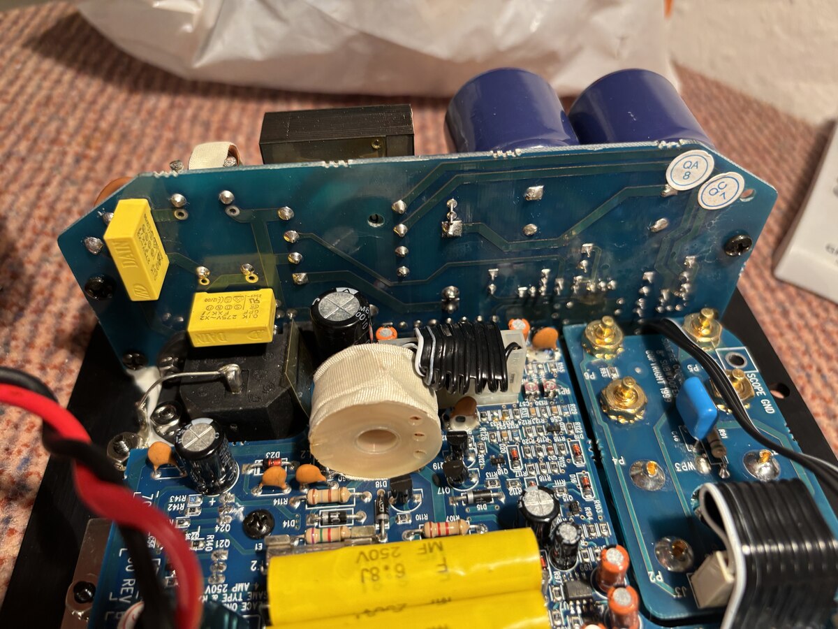
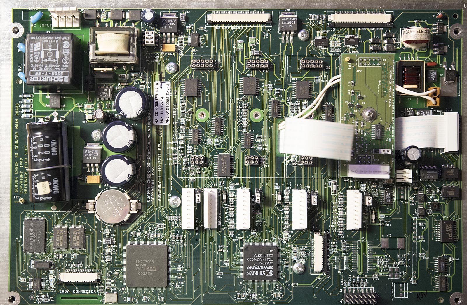
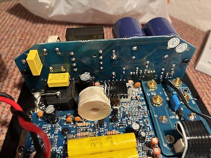
Foto einer Leiterplatte mit Netzteilenkomponenten
QA8 QC1 D23 R43 R14 R110 R111 R112 R113 R114 R115 R116 R117 R118 R119 R120 R121 R122 R123 R124 R125 R126 R127 R128 R129 R130 R131 R132 R133 R134 R135 R136 R137 R138 R139 R140 R141 R142 R143 R144 R145 R146 R147 R148 R149 R150 R151
-
Thread
Beleuchteter Kippschalter beim Laden einer LiFePO₄-Batterie – schädlich?
Okyq-dbglVhplcjPByRL1qUGwfo1dQ7zbui9B5Ez6WG-I9P_A.A-nSp0sda1tWIJayYV24Q7N0mUtlYUHqv_X3jmvdvgk&dib_tag=se&keywords=lifepo4+10a+ladeger%C3%A4t&qid=1751293380&sprefix=liefepo+4+10+a+la%2Caps%2C111&sr=8-49 Kippschalter: https://www.amazon.de/dp/B07TXFR565?ref=ppx_yo2ov_dt_b_fed_asin_title Die Batterie wird ca. 5x pro Woche geladen und entladen. Meine Frage: Kann es für Akku
-
 Bild
Bild
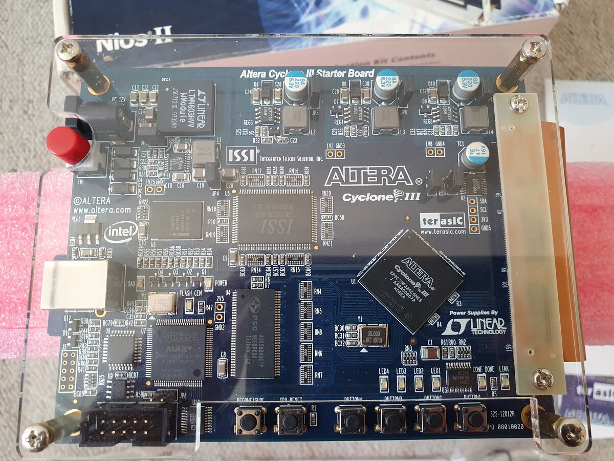
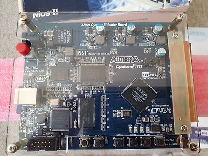
Altera Cyclone III Starter Board
C89 C90 C91 C92 C93 C94 C95 C96 C97 C98 C99 C100 C101 C102 C103 C104 C105 C106 C107 C108 C109 C110 C111 C112 C113 C114 C115 C116 C117 C118 C119 C120 C121 C122 C123 C124 C125 C126 C127 C128 C129 C130 C131 C132 C133 C134 C135 C136 C137 C138 C139 C140 C141 C142 C143 C144 C145 C146 C147 C148 C149 C150 C151
-
 Bild
Bild
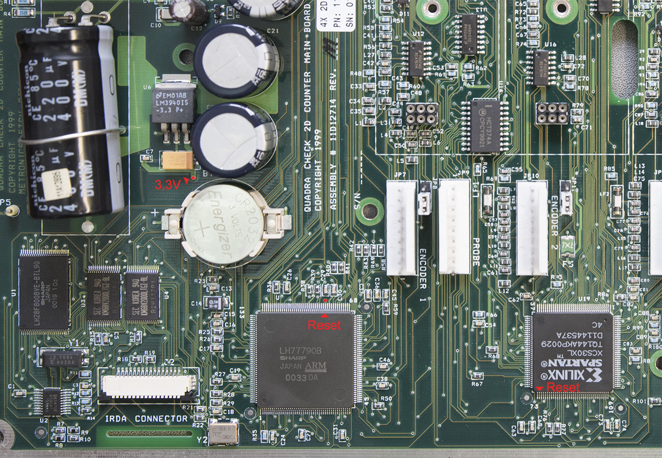
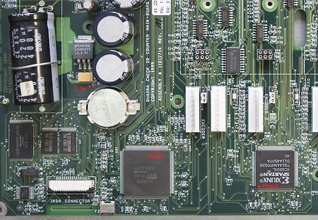
Nahaufnahme einer Leiterplatte mit integrierten Schaltkreisen
C89 C90 C91 C92 C93 C94 C95 C96 C97 C98 C99 C100 C101 C102 C103 C104 C105 C106 C107 C108 C109 C110 C111 C112 C113 C114 C115 C116 C117 C118 C119 C120 C121 C122 C123 C124 C125 C126 C127 C128 C129 C130 C131 C132 C133 C134 C135 C136 C137 C138 C139 C140 C141 C142 C143 C144 C145 C146 C147 C148 C149 C150 C151
-
 Bild
Bild
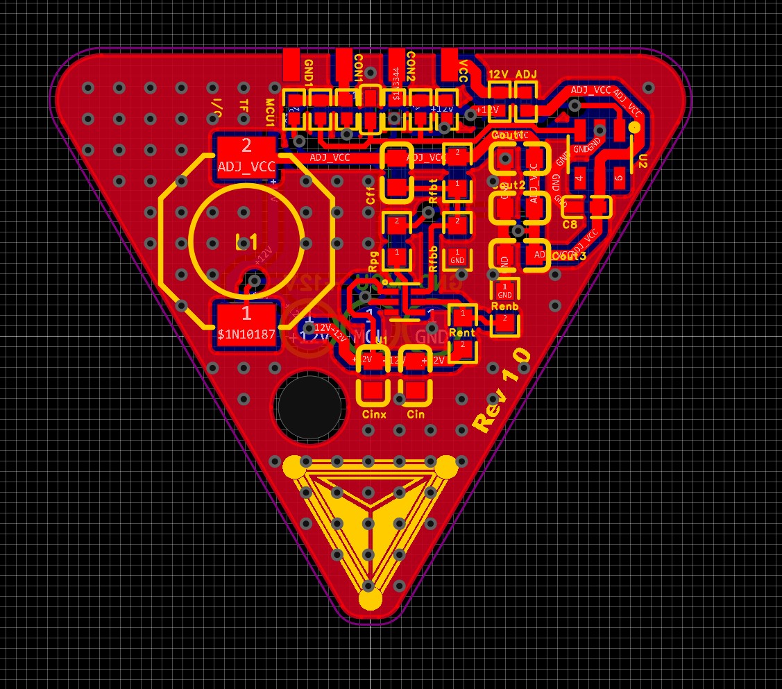
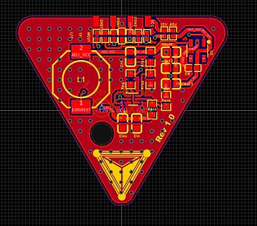
PCB-Layout einer dreieckigen Leiterplatte
C89 C90 C91 C92 C93 C94 C95 C96 C97 C98 C99 C100 C101 C102 C103 C104 C105 C106 C107 C108 C109 C110 C111 C112 C113 C114 C115 C116 C117 C118 C119 C120 C121 C122 C123 C124 C125 C126 C127 C128 C129 C130 C131 C132 C133 C134 C135 C136 C137 C138 C139 C140 C141 C142 C143 C144 C145 C146 C147 C148 C149 C150 C151
-
 Bild
Bild
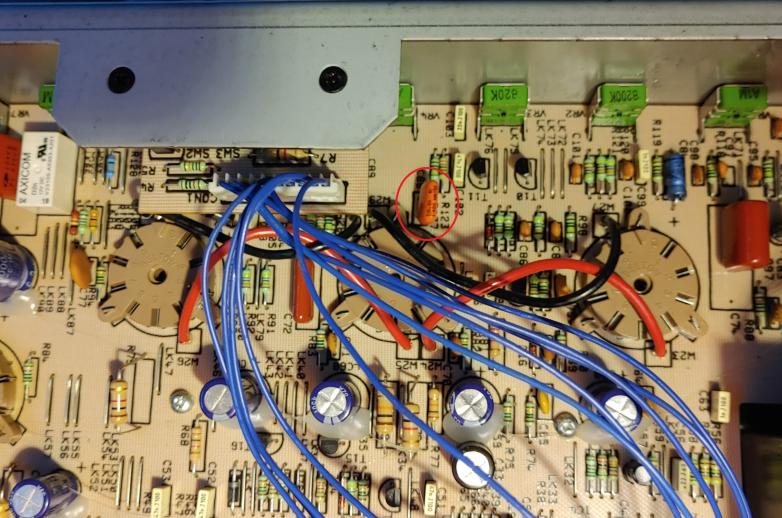
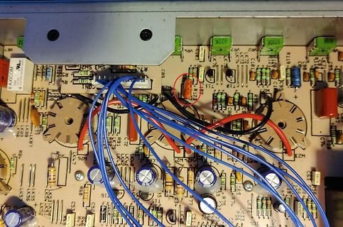
Foto einer bestückten Leiterplatte mit blauen Kabeln
, R94, R95, R96, R97, R98, R99, R100, R101, R102, R103, R104, R105, R106, R107, R108, R109, R110, R111, R112, R113, R114, R115, R116, R117, R118, R119, R120, R121, R122, R123, R124, R125, R126, R127, R128, R129, R130, R131, R132, R133, R134, R135, R136, R137, R138, R139, R140, R141, R142, R143, R144,
-
 Bild
Bild
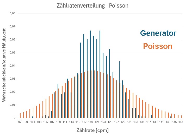
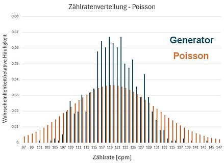
Diagramm der Zählratenverteilung - Poisson
Poisson 0,05 Wahrscheinlichkeit/relative Häufigkeit 0,04 0,03 0,02 0,01 0 97 99 101 103 105 107 109 111 113 115 117 119 121 123 125 127 129 131 133 135 137 139 141 143 145 147 Zählrate [cpm]
-
Thread
Reparatur: Metrawatt M5010 (Installationstester)
Ok, das Gerät misst folgendes: 112V L/PE und 111V L/N. Außerdem leuchtet die PE-LED was bedeutet N/PE >= 100V. Da ist also was im argen.
-
 Bild
Bild
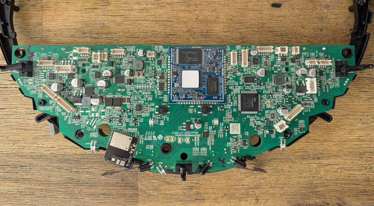
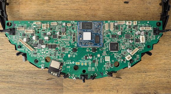
Foto einer bestückten Leiterplatte
SHUANMA050304007 2222 101 102 103 104 105 106 107 108 109 110 111 112 113 114 115 116 117 118 119 120 121 122 123 124 125 126 127 128 129 130 131 132 133 134 135 136 137 138 139 140 141 142 143 144 145 146 147 148 149 150 151 152 153 154 155 156 157 158 159 160 161
-
 Bild
Bild
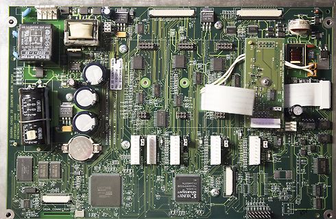
Leiterplatte einer elektronischen Baugruppe
, C94, C95, C96, C97, C98, C99, C100, C101, C102, C103, C104, C105, C106, C107, C108, C109, C110, C111, C112, C113, C114, C115, C116, C117, C118, C119, C120, C121, C122, C123, C124, C125, C126, C127, C128, C129, C130, C131, C132, C133, C134, C135, C136, C137, C138, C139, C140, C141, C142, C143, C144,
-
 Bild
Bild
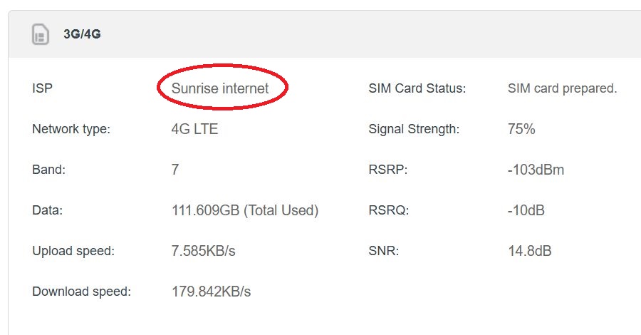
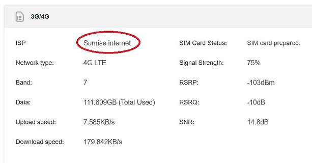
Statusanzeige einer 4G LTE Mobilfunkverbindung
3G/4G ISP: Sunrise internet Network type: 4G LTE Band: 7 Data: 111.609GB (Total Used) Upload speed: 7.585KB/s Download speed: 179.842KB/s SIM Card Status: SIM card prepared. Signal Strength: 75% RSRP: -103dBm RSRQ: -10dB SNR: 14.8dB
-
 Bild
Bild
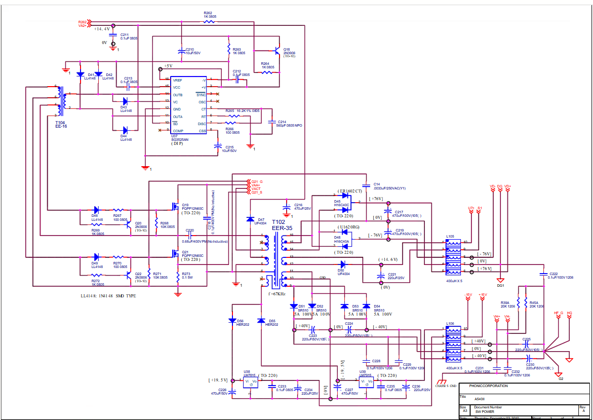
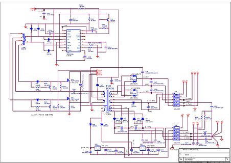
Schaltplan eines Schaltnetzteils
, D94, D95, D96, D97, D98, D99, D100, D101, D102, D103, D104, D105, D106, D107, D108, D109, D110, D111, D112, D113, D114, D115, D116, D117, D118, D119, D120, D121, D122, D123, D124, D125, D126, D127, D128, D129, D130, D131, D132, D133, D134, D135, D136, D137, D138, D139, D140, D141, D142, D143,
-
 Bild
Bild
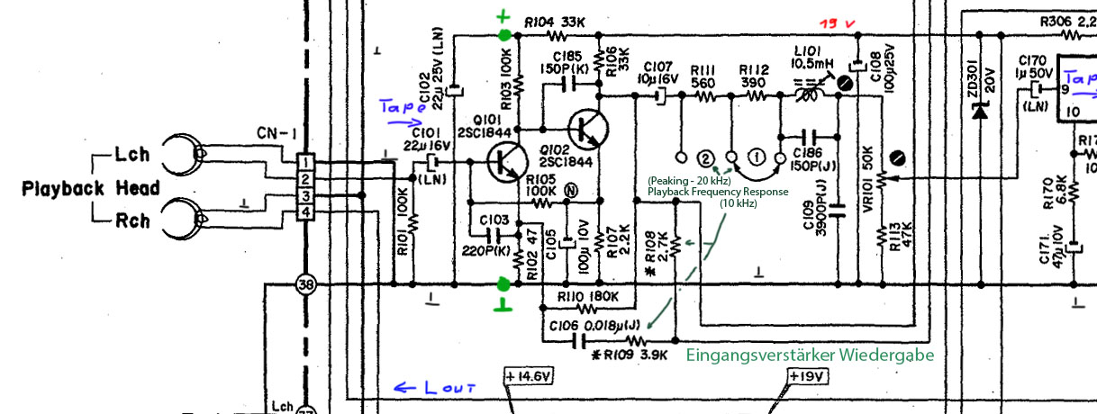
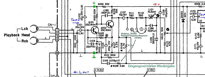
Schaltplan eines Wiedergabeverstärkers
C102 22uV (LN) R104 33K Q102 2SC1844 C103 220P(K) C105 100uF 10V R105 100K R102 47R C107 10uF 16V R111 560 R112 390 L101 10mH C185 150P(K) C186 150P(J) (Peaking - 20 kHz Playback Frequency Response 10 kHz) C109 3900P(J) VR101 50K R113 47K C108 100uF 25V R306 2,2R ZD301 20V C170 50uF (LN) R170 6,8K C171
-
 Bild
Bild
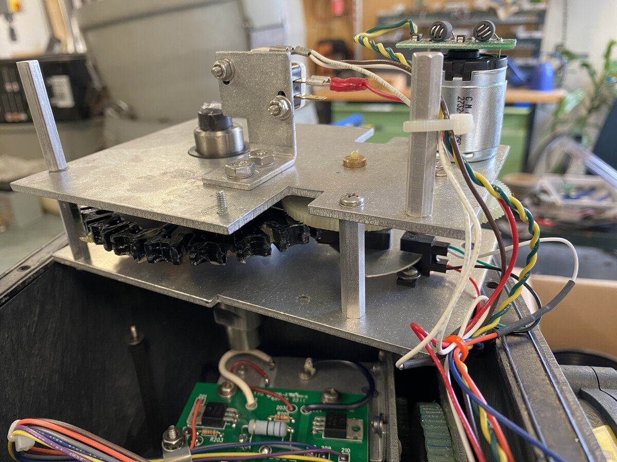
Mechanischer Aufbau mit Motor und Leiterplatte
R89 R90 R91 R92 R93 R94 R95 R96 R97 R98 R99 R100 R101 R102 R103 R104 R105 R106 R107 R108 R109 R110 R111 R112 R113 R114 R115 R116 R117 R118 R119 R120 R121 R122 R123 R124 R125 R126 R127 R128 R129 R130 R131 R132 R133 R134 R135 R136 R137 R138 R139 R140 R141 R142 R143 R144 R145 R146 R147 R148 R149 R150 R151
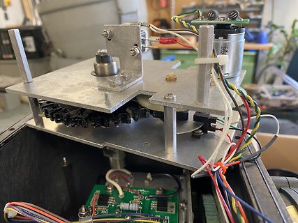
-
Thread
Yamaha Verstärker Widerstand raucht ab
also an VR103 hat der > Schleifer keinen Kontakt mehr. Nö, das Poti ist auf der Emitterseite des Q111. Bei Unterbrechung geht der Ruhestrom auf ein Minimum. Ist also nicht die bekannte Endstufentöterschaltung.
Ich hatte (aus mir unerklärlichem Grunde) zunächst einen pnp-Transistor als Vbe-Multiplizierer Q111 gesehen. Da hätte es sich so verhalten wie beschrieben. Bei einem npn ist es natürlich genau umgekehrt. Nachdem mir die Verwechslung aufgefallen war, habe ich den Beitrag gelöscht.
-
 Bild
Bild
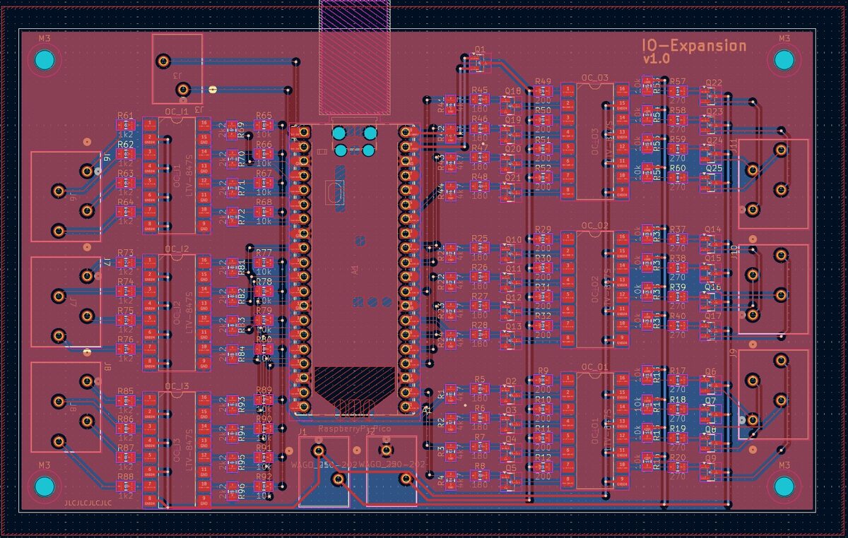
PCB-Layout einer IO-Expansion v1.0
, R94, R95, R96, R97, R98, R99, R100, R101, R102, R103, R104, R105, R106, R107, R108, R109, R110, R111, R112, R113, R114, R115, R116, R117, R118, R119, R120, R121, R122, R123, R124, R125, R126, R127, R128, R129, R130, R131, R132, R133, R134, R135, R136, R137, R138, R139, R140, R141, R142, R143, R144,
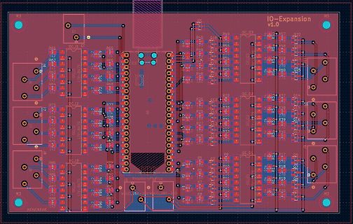
-
 Bild
Bild
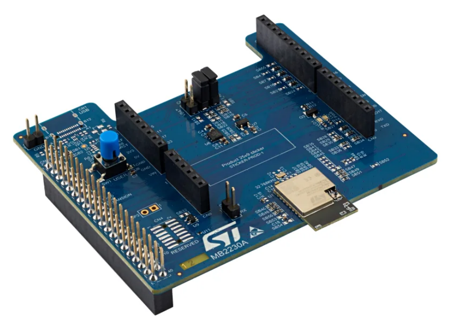
ST MB2230A Erweiterungsplatine
SB94 SB95 SB96 SB97 SB98 SB99 SB100 SB101 SB102 SB103 SB104 SB105 SB106 SB107 SB108 SB109 SB110 SB111 SB112 SB113 SB114 SB115 SB116 SB117 SB118 SB119 SB120 SB121 SB122 SB123 SB124 SB125 SB126 SB127 SB128 SB129 SB130 SB131 SB132 SB133 SB134 SB135 SB136 SB137 SB138 SB139 SB140 SB141 SB142 SB143 SB144
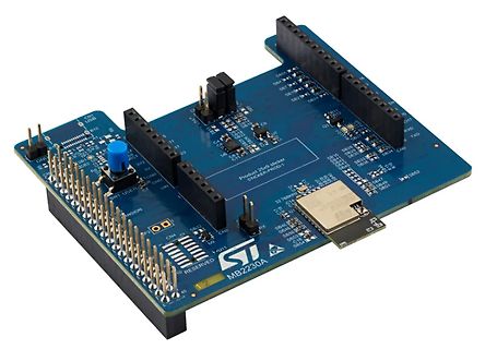
-
 Bild
Bild
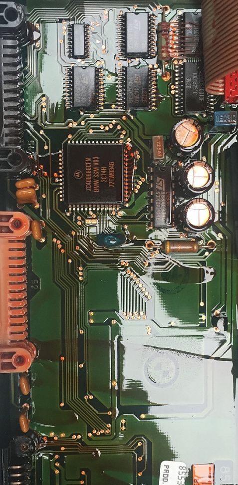
Nahaufnahme einer Leiterplatte mit integriertem Schaltkreis
103J5C 100pF L106 103J5C 100pF L107 103J5C 100pF L108 103J5C 100pF L109 103J5C 100pF L110 103J5C 100pF L111 103J5C 100pF L112 103J5C 100pF L113 103J5C 100pF L114 103J5C 100pF L115 103J5C 100pF L116 103J5C 100pF L117 103J5C 100pF L118 103J5C 100pF L119 103J5C 100pF L120 103J5C 100pF L121 103J5C 100pF L122
-
 Bild
Bild
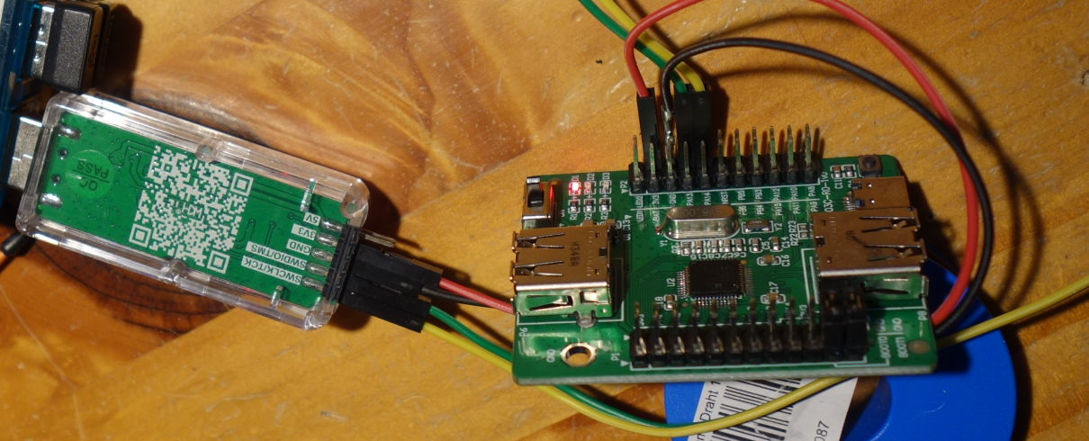
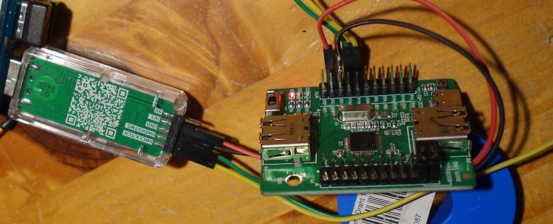
Aufbau mit zwei Leiterplatten und Jumper-Kabeln
, P94, P95, P96, P97, P98, P99, P100, P101, P102, P103, P104, P105, P106, P107, P108, P109, P110, P111, P112, P113, P114, P115, P116, P117, P118, P119, P120, P121, P122, P123, P124, P125, P126, P127, P128, P129, P130
-
 Bild
Bild
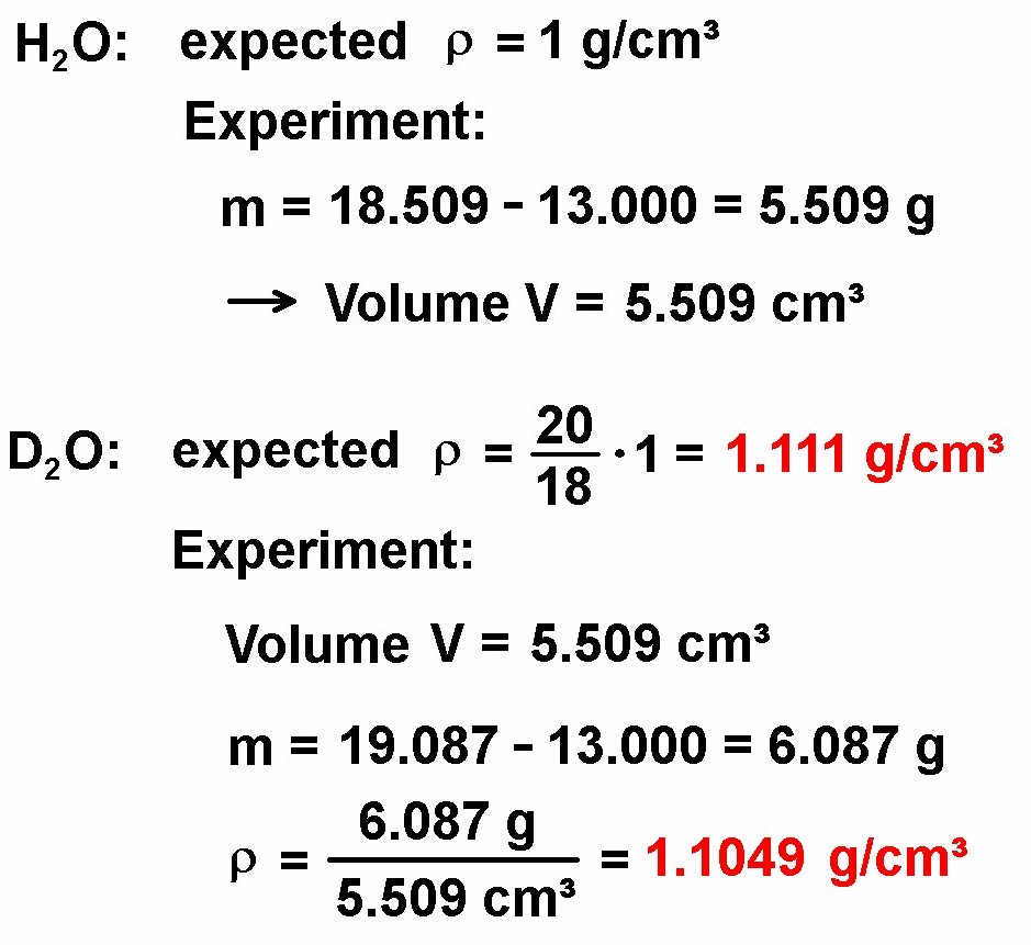
Berechnung der Dichte von H2O und D2O
Experiment: m = 18.509 - 13.000 = 5.509 g → Volume V = 5.509 cm³ D2O: expected ρ = 20/18 * 1 = 1.111 g/cm³ Experiment: Volume V = 5.509 cm³ m = 19.087 - 13.000 = 6.087 g ρ = 6.087 g / 5.509 cm³ = 1.1049 g/cm³

-
 Bild
Bild
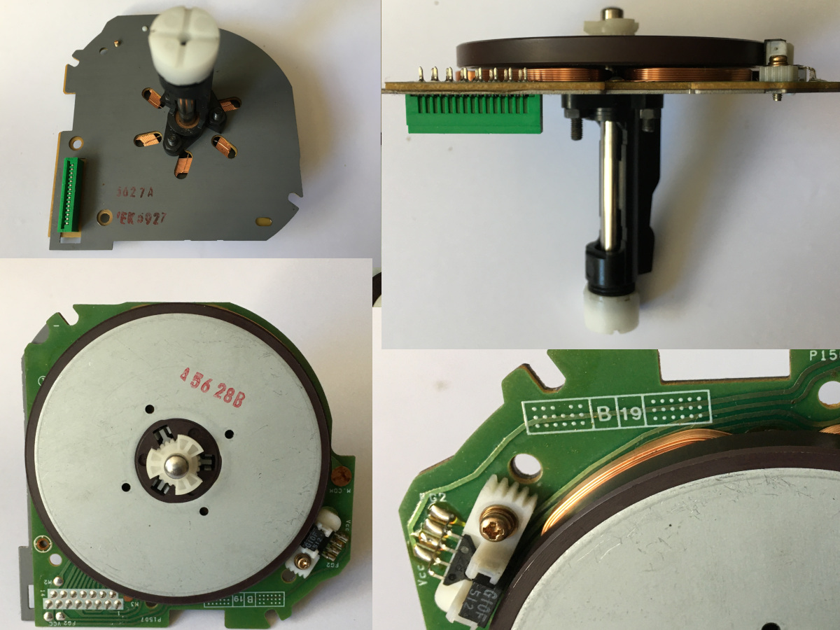
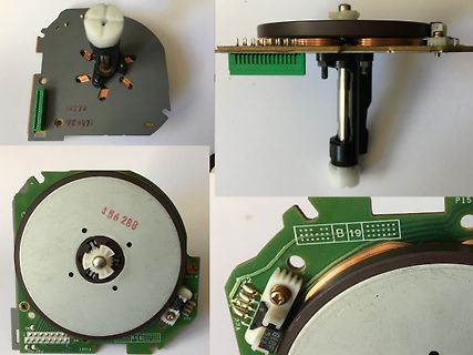
Nahaufnahmen eines Drehreglers mit Leiterplatte
F89 F90 F91 F92 F93 F94 F95 F96 F97 F98 F99 F100 F101 F102 F103 F104 F105 F106 F107 F108 F109 F110 F111 F112 F113 F114 F115 F116 F117 F118 F119 F120 F121 F122 F123 F124 F125 F126 F127 F128 F129 F130 F131 F132 F133 F134 F135 F136 F137 F138 F139 F140 F141 F142 F143 F144 F145 F146 F147 F148 F149 F1
-
 Bild
Bild
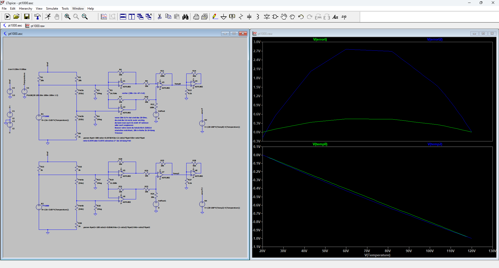
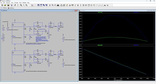
Simulink Modell und Diagramme von Spannungsverläufen
R89 R90 R91 R92 R93 R94 R95 R96 R97 R98 R99 R100 R101 R102 R103 R104 R105 R106 R107 R108 R109 R110 R111 R112 R113 R114 R115 R116 R117 R118 R119 R120 R121 R122 R123 R124 R125 R126 R127 R128 R129 R130 R131 R132 R133 R134 R135 R136 R137 R138 R139 R140 R141 R14
-
 Bild
Bild
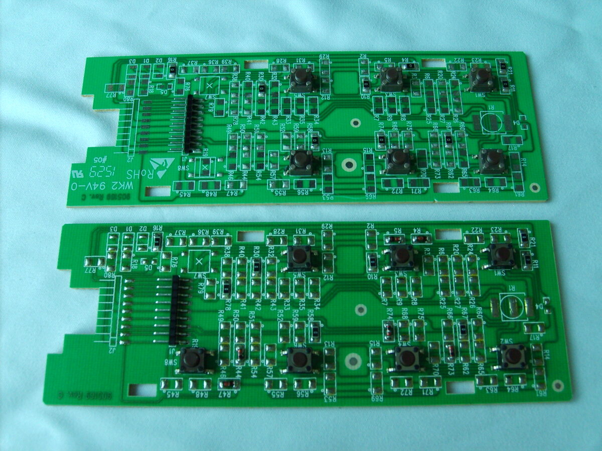
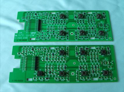
Zwei grüne Leiterplatten mit Schaltern und Widerständen
R89 R90 R91 R92 R93 R94 R95 R96 R97 R98 R99 R100 R101 R102 R103 R104 R105 R106 R107 R108 R109 R110 R111 R112 R113 R114 R115 R116 R117 R118 R119 R120 R121 R122 R123 R124 R125 R126 R127 R128 R129 R130 R131 R132 R133 R134 R135 R136 R137 R138 R139 R140 R141 R142 R143 R144 R145 R146 R147 R148 R149 R150 R151
-
 Bild
Bild
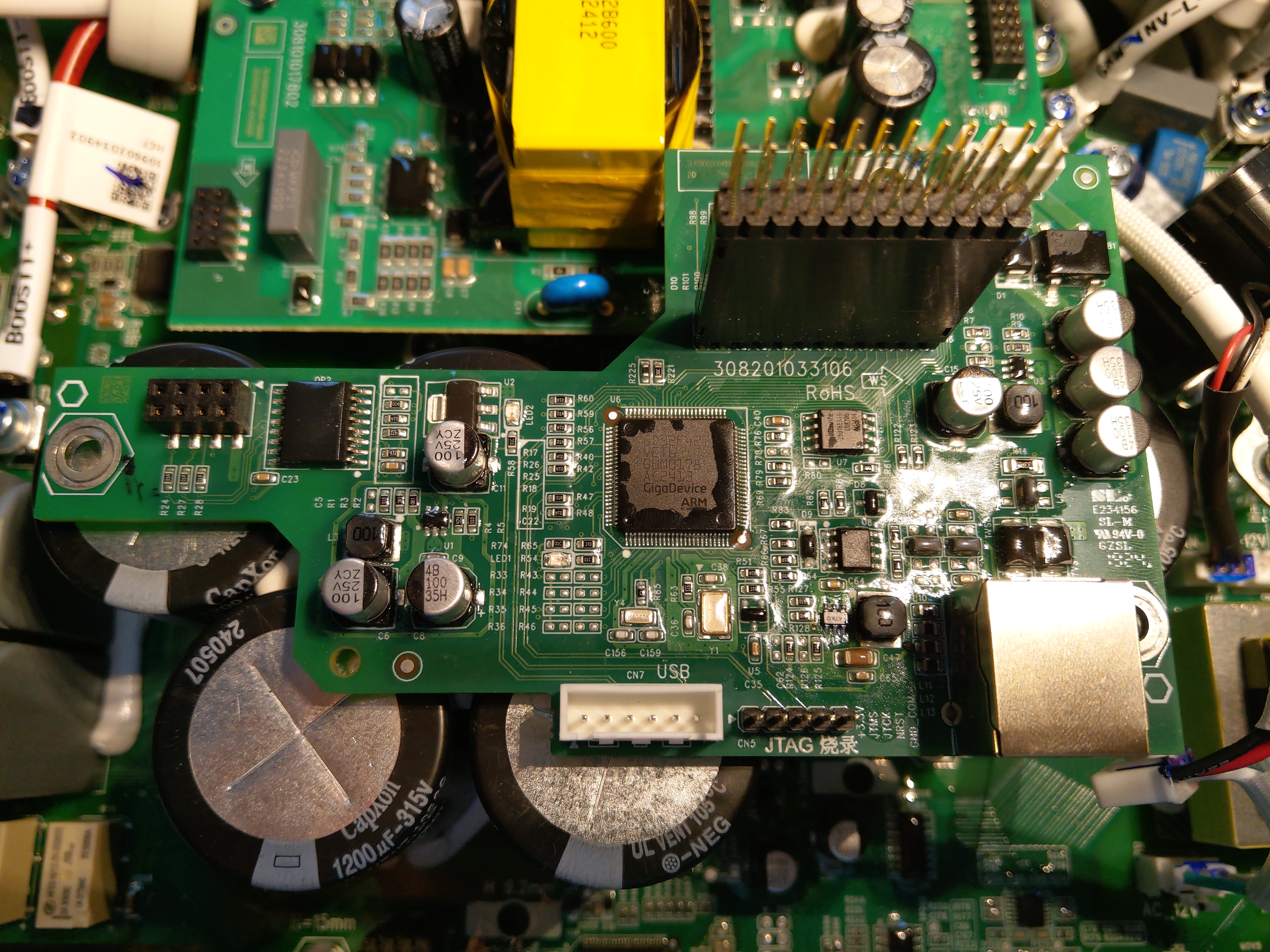
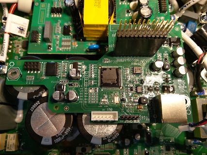
Nahaufnahme einer Leiterplatte mit integriertem Chip
C89 C90 C91 C92 C93 C94 C95 C96 C97 C98 C99 C100 C101 C102 C103 C104 C105 C106 C107 C108 C109 C110 C111 C112 C113 C114 C115 C116 C117 C118 C119 C120 C121 C122 C123 C124 C125 C126 C127 C128 C129 C130 C131 C132 C133 C134 C135 C136 C137 C138 C139 C140 C141 C142 C143 C144 C145 C146 C147 C148 C149 C150 C151
-
 Bild
Bild
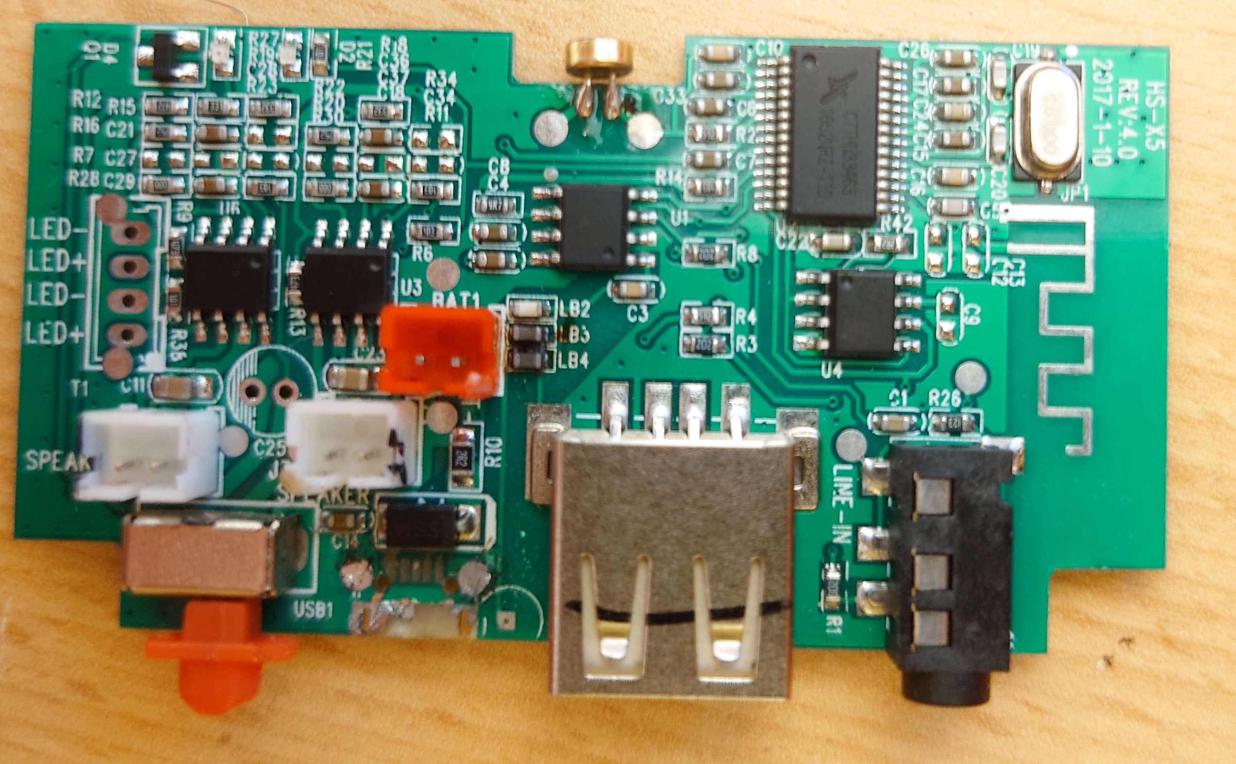
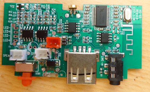
Leiterplatte mit USB, Audio-Anschlüssen und integrierten ICs
C89 C90 C91 C92 C93 C94 C95 C96 C97 C98 C99 C100 C101 C102 C103 C104 C105 C106 C107 C108 C109 C110 C111 C112 C113 C114 C115 C116 C117 C118 C119 C120 C121 C122 C123 C124 C125 C126 C127 C128 C129 C130 C131 C132 C133 C134 C135 C136 C137 C138 C139 C140 C141 C142 C143 C144 C145 C146 C147 C148 C149 C150 C151
-
 Bild
Bild
Infografik zu MS Office Marktanteil und Mitarbeiter Output
Output pro mit der Anwendung arbeitender Mitarbeiter pro Woche 2 Präsentationen 5 Dokumente 3 Tabellen 111 E-Mails 23 h arbeitet ein Mitarbeiter durchschnittlich in der Woche in allen Office-Anwendungen. 30% Anteil der Zeit, die mit der Formatierung und nicht mit den Inhalten verbracht wird.

-
 Bild
Bild
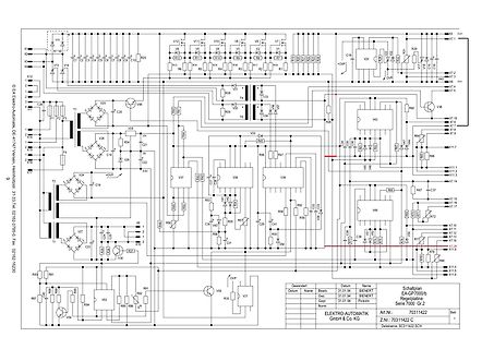
Schaltplan einer elektronischen Schaltung
, X94, X95, X96, X97, X98, X99, X100, X101, X102, X103, X104, X105, X106, X107, X108, X109, X110, X111, X112, X113, X114, X115, X116, X117, X118, X119, X120, X121, X122, X123, X124, X125, X126, X127, X128, X129, X130, X131, X132, X133, X134, X135, X136, X137, X138, X139, X140, X141, X142, X14
-
 Bild
Bild
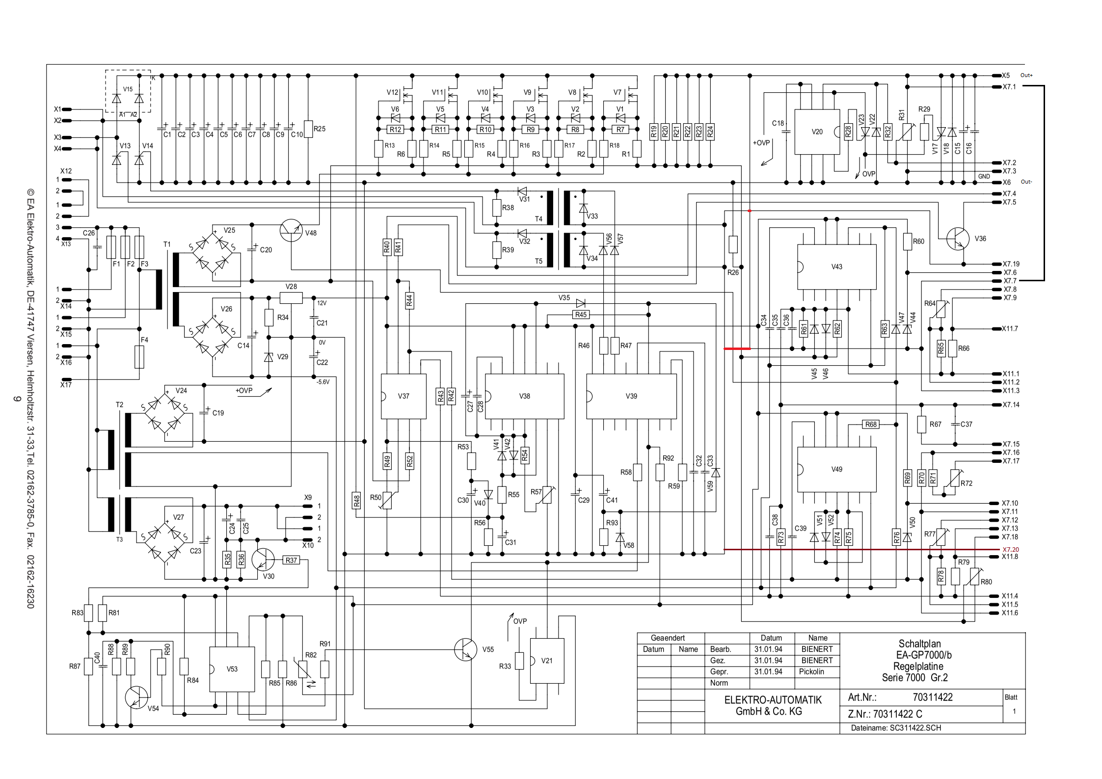
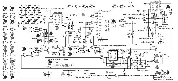
Schaltplan eines Netzteils
R88 R89 R90 R91 R92 R93 R95 R96 R97 R98 R99 R100 R101 R102 R103 R104 R105 R106 R107 R108 R109 R110 R111 R112 R113 R114 R115 R116 R117 R118 R119 R120 R121 R122 R123 R124 R125 R126 R127 R128 R129 R130 R131 R132 R133 R134 R13
-
 Bild
Bild
Nahaufnahme einer Leiterplatte mit integrierten Bauteilen
R131 R130 R129 R128 R127 R126 R125 R124 R123 R122 R121 R120 R119 R118 R117 R116 R115 R114 R113 R112 R111 R110 R109 R108 R107 R106 R105 R104 R103 R102 R101 R100

-
 Bild
Bild
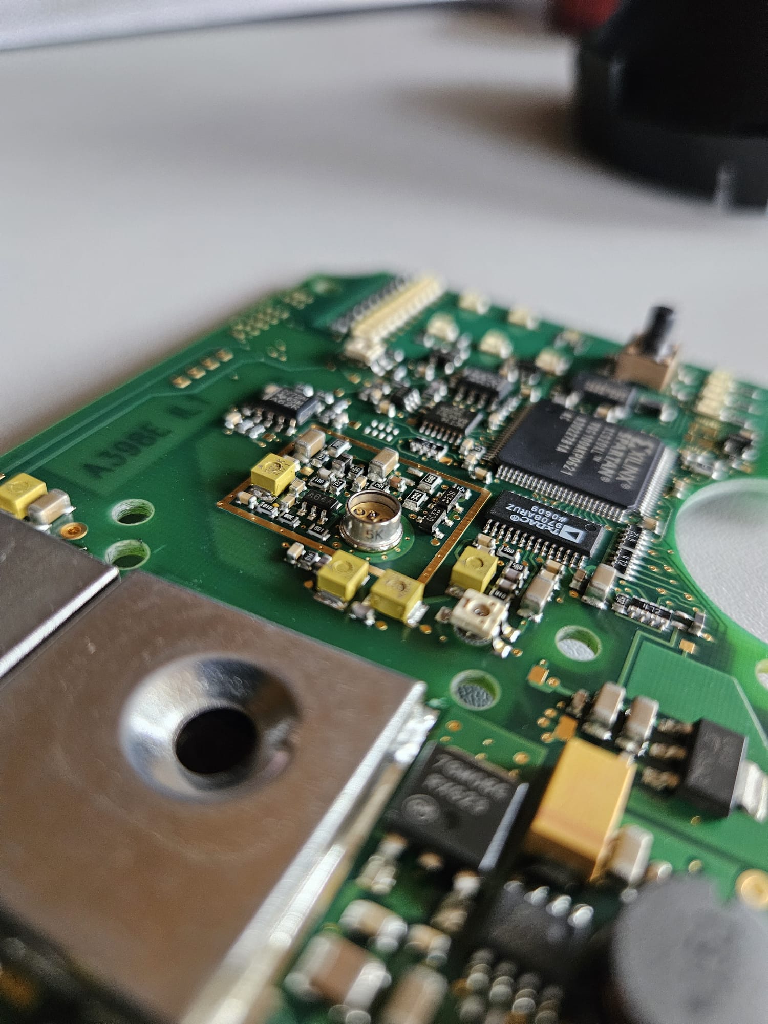
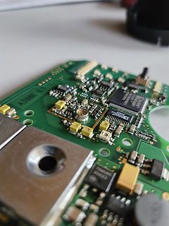
Nahaufnahme einer Leiterplatte mit integriertem Chip
A398E, SYLVANIA, 101, 102, 103, 104, 105, 106, 107, 108, 109, 110, 111, 112, 113, 114, 115, 116, 117, 118, 119, 120, 121, 122, 123, 124, 125, 126, 127, 128, 129, 130, 131, 132, 133, 134, 135, 136, 137, 138, 139, 140, 141, 142, 143, 144, 145, 146, 147, 148, 149, 150, 151
-
 Bild
Bild
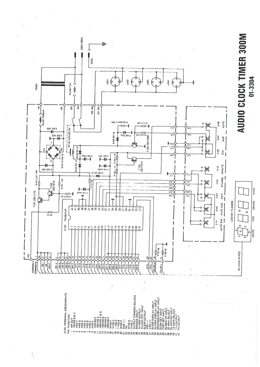
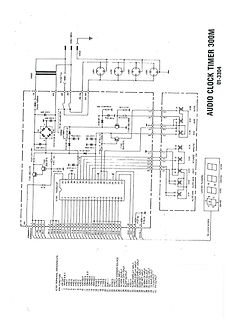
Schaltplan eines Audio Clock Timers
COM 99 COM 100 COM 101 COM 102 COM 103 COM 104 COM 105 COM 106 COM 107 COM 108 COM 109 COM 110 COM 111 COM 112 COM 113 COM 114 COM 115 COM 116 COM 117 COM 118 COM 119 COM 120 COM 121 COM 122 COM 123 COM 124 COM 125 COM 126 COM 127 COM 128 COM 129 COM 130 COM 131
-
 Bild
Bild
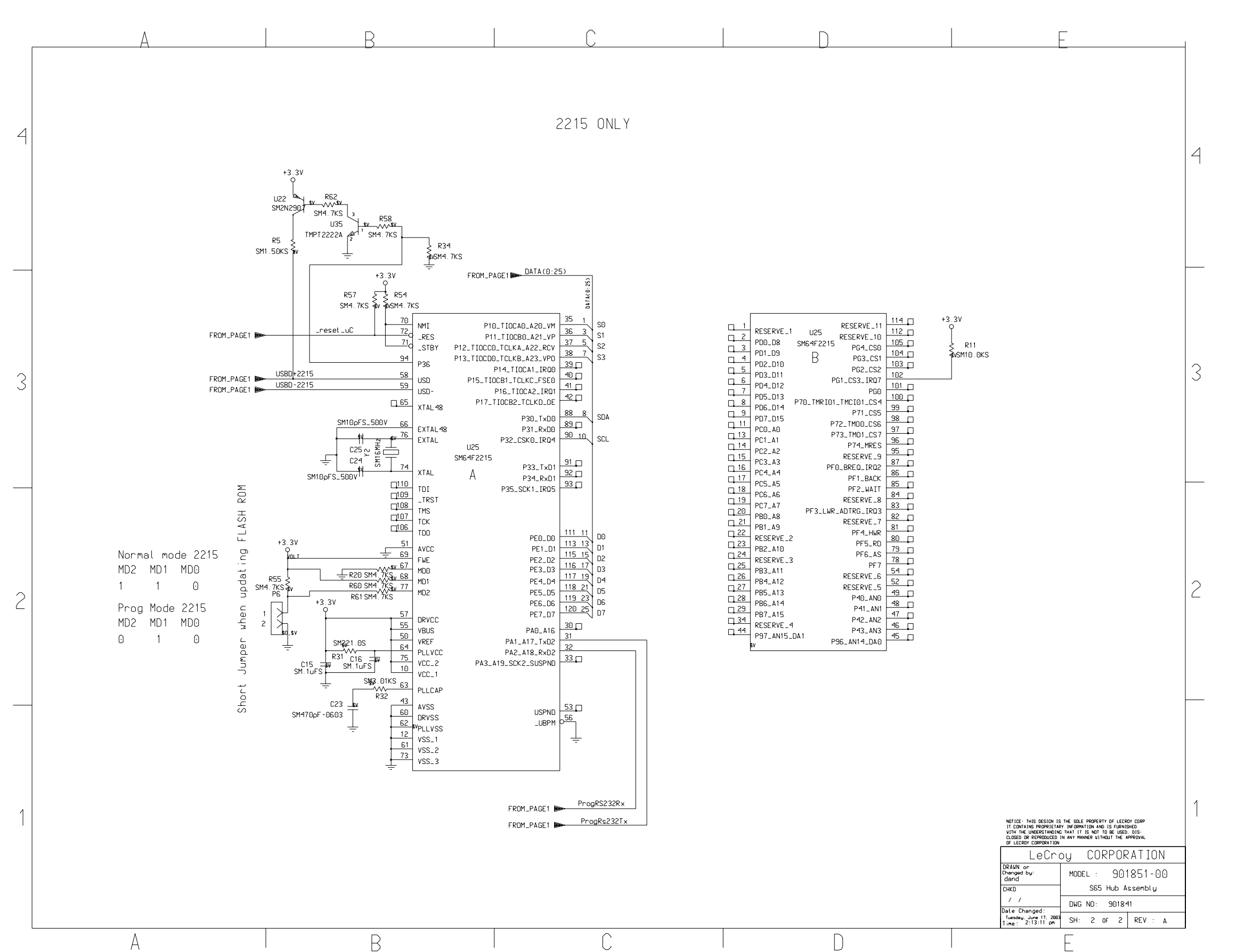
Schaltplan eines Mikrocontrollers mit SM47F06-0603
, R94, R95, R96, R97, R98, R99, R100, R101, R102, R103, R104, R105, R106, R107, R108, R109, R110, R111, R112, R113, R114, R115, R116, R117, R118, R119, R120, R121, R122, R123, R124, R125, R126, R127, R128, R129, R130, R131, R132, R133, R134, R135, R136, R137, R138, R139, R140, R141, R142, R143, R144,